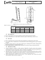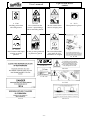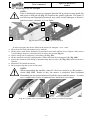
1
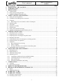
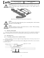
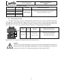
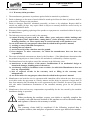
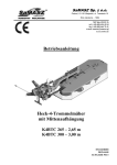
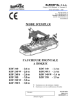
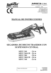
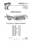
SaMASZ Sp. z o.o.
Poland, 15-161 Białystok, ul. Trawiasta 15
Established – 1984
NIP 966-159-29-76
tel. (+48) (85) 654 45 84
fax (+48) (85) 664 70 41
e-mail: [email protected]
www.samasz.pl
OPERATOR'S MANUAL
REAR DISK
MOWER
SAMBA 160
SAMBA 200
SAMBA 240
SAMBA 280
– 1.6 m
– 2.0 m
– 2.4 m
– 2.8 m
IN0670EN001
2014.01.20
EDITION NO. 1
Nr. Serial no.
Original manual
It is recommended to incline cutterbar up to angle of
3° in relation to mowing direction.
Operating in horizontal position is admissible.
DO NOT
TURN THE DRIVE ON UNLESS THE
MOWER IS IN ITS WORKING
POSITION
DO NOT
OPERATE THE MOWER WITH
UNAUTHORIZED PERSONNEL
PRESENT WITHIN 50 M OR LESS
NOTE:
Keep this manual for future reference.
Written by: mgr inż. Jakub Gościk
User's manual
Light rear disk mowers
SAMBA
Table of contents
page
1. IDENTIFYING THE MACHINE ............................................................................................... 2
2. INTRODUCTION......................................................................................................................... 2
3. DESIGNATION ............................................................................................................................ 3
3.1. Technical data .......................................................................................................................................... 3
3.2. Design and operating principle ................................................................................................................ 4
3.3. Standard equipment and spare parts ........................................................................................................ 4
4.
SAFETY ADVICE AND WARNING ......................................................................................... 5
4.1. Safety rules and regulations ..................................................................................................................... 5
4.2. Conditions of mounting mower on tractor............................................................................................... 7
4.3. Transport .................................................................................................................................................. 7
4.3.1. Relocating mower onto another vehicle for transport ........................................................................ 8
4.4. Operating parts ........................................................................................................................................ 9
4.5. PTO shaft ................................................................................................................................................. 9
4.6. Hydraulic assembly ................................................................................................................................. 9
4.7. Residual risk .......................................................................................................................................... 10
4.8. Safety decals and their meaning ............................................................................................................ 11
4.9. Operation and design of safety breakaway device................................................................................. 13
5.
MOWER'S OPERATION.......................................................................................................... 14
5.1. Mounting mower on tractor ................................................................................................................... 14
5.2. Preparing mower for transport ............................................................................................................... 15
5.3. Preparing mower for transport on public roads ..................................................................................... 16
5.4. Mounting PTO shaft .............................................................................................................................. 16
5.5. Switching the mower from transport to working position ..................................................................... 17
5.6. Preparing mower for operation .............................................................................................................. 18
5.7. Operation ............................................................................................................................................... 18
5.7.1. Basic information on mowing .......................................................................................................... 18
5.7.2. Mower clogging................................................................................................................................ 19
5.7.3. Driving with mower over windrows when taking turns ................................................................... 19
5.8. Dismounting mower from tractor .......................................................................................................... 19
6.
MOUNTING AND ADJUSTMENTS ....................................................................................... 20
6.1. Mounting knives .................................................................................................................................... 20
6.2. Replacing knives.................................................................................................................................... 21
6.3. Adjusting cutting height ........................................................................................................................ 22
6.4. Operating service ................................................................................................................................... 22
6.4.1. Controlling condition of knives and knife holders ........................................................................... 22
6.4.2. Controlling tension of V-belts for belt gear...................................................................................... 23
6.4.3. Daily maintenance ............................................................................................................................ 23
6.4.4. Off-season maintenance and storing................................................................................................. 23
7.
LUBRICATING .......................................................................................................................... 24
7.1. Cutterbar ................................................................................................................................................ 24
7.2. Intersecting axis gear ............................................................................................................................. 25
8.
9.
DEFECTS AND THEIR REPAIR ............................................................................................ 26
REPAIR AND WITHDRAWAL FROM USE ......................................................................... 27
9.1. Repair..................................................................................................................................................... 27
9.2. Withdrawal from use ............................................................................................................................. 27
10. WARRANTY CARD .................................................................................................................. 27
11. WARRANTY TERMS ............................................................................................................... 28
11.1. Warranty claim procedure ..................................................................................................................... 28
11.2. Warranty repairs record ......................................................................................................................... 29
-1-
Light rear disk mowers
SAMBA
User's manual
1. IDENTIFYING THE MACHINE
Data plate is permanently mounted to the mower's main frame in place shown below on
Fig. 1.
Fig. 1. Data plate placement
Data plate includes:
- name of the manufacturer,
- mower serial number,
- mower symbol,
- date of manufacture,
- weight,
- version no.,
- quality management sign,
- CE marking, means that mower is conforming
with Directive 2006/42/EC and harmonized
standards,
- MADE IN POLAND sign,
- barcode.
NOTE:
In case the operator's manual is unclear or illegible all necessary information
can be obtained from manufacturer or the dealer.
2. INTRODUCTION
This operator's manual should be considered the mower's basic equipment and should be kept for
further reference. If the mower is handed over to another operator, it should be in working
condition, along with operator's manual, declaration of conformity and its basic equipment.
Prior to operating the mower its user must familiarize himself with contents of this manual as well
as common work safety rules.
The mower is manufactured in accordance with safety standards requirements.
Respecting recommendations herein shall ensure full operation safety.
If you have any questions concerning commissioning and operating the mower, please contact the
manufacturer.
Operator's manual remains an integral part of the mower equipment.
GENERAL PRECAUTION
When operating the mower warnings and safety rules marked with this
sign herein should be respected.
NOTE:
Operating the mower without previous familiarizing with its contents as well as
by unauthorized personnel, particularly by children, is strictly forbidden.
-2-
Light rear disk mowers
SAMBA
User's manual
3. DESIGNATION
Light class rear disk mowers SAMBA are designed to operate on smaller farms, and are used for
mowing standing grass: common grass, medick, etc on meadows and on stone free fields as well as
forming swath out of these. They do well in mountainous as well as swamp areas, where the machine's
and tractor's weight is of great importance. Application of innovative suspension assembly allows for
adjusting optimal pressure of cutterbar onto the ground.
Meadows or fields to be mowed should be even, previously prepared by rolling and other
processing.
NOTE:
Use of the mower for purposes other than mentioned herein is forbidden.
Different use than the above mentioned shall be considered as improper and
may lead to revoking of the warranty. The mower should be operated,
maintained and repaired only by personnel who are familiarized with its
detailed specifications and safety rules and procedures. Willful modifications to
the mower may lead to revoking the warranty.
NOTE:
SAMBA mowers are not fully resistant to stones and therefore when operating
on a stony field, it is highly likely, that disks might be replaced frequently or in
extreme case, cutterbar might be seriously damaged, which is NOT COVERED
by free warranty servicing.
3.1. Technical data
Tab. 1. Technical data
Mower type:
Working width [m]
Number of knives [pcs]
Number of disks [pcs]
Tractor's PTO rears [rpm]
Cooperating tractor power [HP]
Operating capacity [ha/h]
Transport length [mm]
Transport width [mm]
Width in working assembly [mm]
Transport height [mm]
Weight [kg]
Cutting speed of knife [m/s]
Rotational speed of disks [rpm]
3-point linkage category
SAMBA 160
SAMBA 200
SAMBA 240
SAMBA 280
1.60
8
4
2.00
10
5
2.40
12
6
2.80
14
7
from 20
~ 1.5
from 30
~ 2.0
from 45
~ 2.5
from 60
~ 3.0
4230
2900
490
4504
3280
530
540
1782
1695
3680
2140
410
3956
2520
450
83
3115
II
II
77,0 ± 3,0 dB
76,0 ± 3,0 dB
98,5 ± 3,0 dB
LpA – noise level related to 8 hour working time. Averaged in time acoustic pressure level corrected by
frequency characteristic A.
LAmax – maximum value corrected by frequency characteristic A of acoustic pressure level.
LCpeak – peak level of acoustic pressure corrected by frequency characteristic C.
Noise level
II
II
LpA
LAmax
LCpeak
-3-
Light rear disk mowers
SAMBA
User's manual
3.2. Design and operating principle
1
2
3
5
4
6
7
8
Fig. 2. Overview of rear disk mower SAMBA
1 – Linkage
2 – Cylinder with support spring
3 – Belt gear
4 – Cutterbar
5 – Swath guide
6 – Safety guard
7 – Disk type swath guide (option)
8 – 3-point linkage frame
Linkage (1) allows mounting mower on tractor's 3-point linkage. Drive from tractor's PTO is
transmitted by belt gear (3) onto LiteCUT cutterbar (4). Hydraulic lifting cylinder (2) fed from the
tractor external hydraulics is used to adjust the mower to working position. 3-point linkage frame (8),
onto which spring suspended cutterbar is set. The frame has also swath guides (5), which are standarddelivered, optional disk type guides (7) and protective guard (6).
Well-proven design and quality materials ensure high reliability and durability of SaMASZ machines.
3.3. Standard equipment and spare parts
Mowers are sold with the following standard equipment:
warranty card,
operator's manual with spare part list,
cutting knives: extra set,
PTO shaft with overrunning clutch,
spray paint (150 ml).
Optional equipment (on extra charge):
warning plates with combined lights and reflectors,
warning triangle,
double rubber guide.
-4-
Light rear disk mowers
SAMBA
User's manual
Tab. 2. Recommended PTO shaft
Mower
SAMBA 160
SAMBA 200
SAMBA 240
SAMBA 280
Ref
Clutch
Manufactur
er
mm
Moment
um
Nm
660-900
460
7G3N066CE007096MA
Right-hand
overrunning
BONDIOLI
& PAVESI
Power
Length
HP
35
PTO shaft end without clutch
– To be mounted on the tractor
side
50 h
50 h
50 h
Remarks
PTO shaft end with right
overrunning clutch – To be
mounted from the mower side
50 h
Fig. 3. Shaft lubrication instructions. Shaft connection
NOTE:
PTO shaft lubrication frequency must be respected. Points marked on Fig. 3
shall be lubricated every 50 hours. PTO shaft should also be lubricated prior to
and after longer idle period.
PTO shafts of other brands with equivalent technical parameters may be used on the SaMASZ
permission.
NOTE:
Optional equipment should be ordered separately.
The mower is equipped with such elements as holders and brackets used to mount required
warning lights and plates. Combined lights and reflectors are mounted on the warning plates.
We congratulate you on the purchase of your new SaMASZ mower and wish you much pleasure and
the very best experience resulting from its operation.
4. SAFETY ADVICE AND WARNING
4.1. Safety rules and regulations
Front axis of the tractor should be loaded by a minimum of 20% of tractor's overall weight to keep
the balance. If need be, use front wheel weights.
Any operation with the hydraulic lift lever should be conducted from the operator's seat; DO NOT
move the lever from outside of the tractor.
In case of tractors equipped with EHR, controlling with hydraulic lift is conducted with a button
located outside the tractor's cabin. When operating, please be extremely careful.
When switching from working to transport position the whole or at least one end (from tractor's
spline shaft side) of PTO shaft should be dismounted.
-5-
User's manual
Light rear disk mowers
SAMBA
Examine condition of guards and its mounting on regular basis. Operating without safety guards is
not permitted. Neither operation with damaged or raised guard is permitted (danger of stones, etc.
being thrown out). Damaged protective apron should be replaced with a new one.
Start mowing only when the tractor's spline shaft reaches its nominal value of 540 rpm.
DO NOT exceed value of 600 rpm for spline shaft.
No unauthorized personnel is allowed to remain within the danger area of at least 50 m. Keep
particular caution when operating near roads and in stony areas.
Any maintenance and adjustment work is allowed only with the drive disconnected and the cutting
disks in complete standstill and wearing protective gloves and appropriate tools.
Condition of knives should be examined each time before commencing any operation. Damaged or
worn knife holders must be replaced.
When driving on public roads always respect the local traffic regulations concerning warning
-lights, while the mower shall be equipped with required safety devices. When transported the
mower shall have remote warning light device and warning triangle mounted.
NOTE:
Any service and repair operations must be conducted with the tractor drive
disconnected and ignition key out, cutterbar lifted onto the ground while all
rotating parts in the complete standstill. Caution! Cutting knives keep rotating
for several minutes after the engine is stopped.
NOTE:
Keep the children away from the mower both in operation and standstill.
When the mower is lifted for repair on the 3-point linkage, it should be protected against accidental
falling by a mechanical support or by chain.
Bolts and other fasteners should be inspected on regular basis. Operating with damaged or worn
fasteners is not admissible.
Locking pawl line should be mounted with relevant tolerance in the tractor cabin.
When operating the mower, please comply with the Resolution of the Minister of Agriculture and
Food Economy of 12-01-1998 on work safety when operating tractors, machines, technical
instruments and devices used in farming Dz. U. nr 12/98 poz. 51.
When operating the mower, the tractor should always be equipped with operator's cabin.
Mower should not be operated when the cooperating tractor is not well balanced.
The mower shall never be started when it is lifted up.
The mower shall never be started, with persons or animals near the machine.
Prior to starting the mower, make sure there are no animals underneath the tarpaulin cover.
The safety guard shall never be lifted until rotating assemblies are in complete standstill. Tractor's
engine must be turned off. Caution! Cutting knives keep rotating for several minutes after the
engine is stopped.
Always comply with safety decals describing hazards, and warning signs placed on the machine.
Before starting the tractor make sure that each drive is disconnected while the hydraulics control
levers are in neutral position.
Do not let the tractor's engine operate without any supervision. Before leaving the tractor, turn the
engine off and take the ignition key out.
It is forbidden to drive the mower backwards when operating.
Never get onto the mower.
-6-
User's manual
Light rear disk mowers
SAMBA
Lifting the mower on the tractor 3-point linkage with the drive on and the disks rotating is not
permitted.
For operating and transport drive permissible slope shall be 8°.
Never stand between the tractor and the mower, unless tractor-mower aggregate is protected
against moving with the tractor's parking brake.
Any maintenance checkups and regulations may be conducted only when the mower is
disassembled and on the ground.
If any maintenance or adjustment works under the lifted mower are necessary, it must be secured
against falling with a support.
If any part of the mower needs to be replaced, use only genuine spare parts according to catalogue
of spare parts.
Pay particular attention to both PTO shaft and spline shaft guards. Never operate with damaged
guards.
Hydraulic hoses should be inspected on regular basis and if any damage is found or they expire,
replace these with new ones. Expiry period for hydraulic hose should be no longer than 5 years.
Never use scotch tape to repair damaged hydraulic hoses.
When connecting hydraulic hoses to tractor hydraulic connectors make sure, that either tractor or
mower hydraulics are pressure free.
When servicing hydraulic assembly, always wear protective gloves and eyewear. Hydraulic oil
leaking under pressure (16 MPa) may permeate through the skin and cause its infection thereafter.
If such is experienced, immediately visit a doctor.
The mower should be stored under roof and in manner that effectively prevents animals and
persons from being injured.
Operating without safety guards is not permitted. Neither operation with damaged or raised guard
is permitted (danger of stones, etc. being thrown out). Damaged protective apron should be
replaced with a new one.
When operating the mower, control damages to structures, protective aprons, chains, rubber
elements and if need be, replace these with new ones, even not completely worn out elements.
When mounting the mower on a tractor, danger of wounding is present. It is recommended for the
operator to wear protective gloves.
In the event of fatal failure, please call for technical service, and if an accident (in this case: road
accident) occurs, respect first aid rules and contact responsible authorities.
Mower should be kept clean, so as to avoid danger of fire.
Do not leave agricultural machinery on slopes or other descents without providing protection
against its free runaway.
4.2. Conditions of mounting mower on tractor
Prior to the mounting operation, check whether the tractor's and the mower's hitch categories are
compatible and make sure that tractor's hitch load is adequate for the machine aggregated.
When mounting the machine, examine technical condition of the mower's hitch assembly
and tractor's 3-point linkage.
Use only genuine pins and cotters to mount the mower on a tractor.
4.3. Transport
Any modifications in the mower's position are possible only if no unauthorized personnel is around
(children in particular).
-7-
User's manual
Light rear disk mowers
SAMBA
When transported the mower shall have mobile warning light device and warning triangle mounted
for a slow driving vehicle.
When transported the mower should always be set in transport position. See item 5.2.
Prior to shifting the mower to transport position make sure, that the tractor PTO is disconnected
and all the rotating parts in complete standstill.
Driving speed should always be adjusted to current road conditions.
Driving speed should always be adjusted to current road conditions and local traffic rules.
4.3.1. Relocating mower onto another vehicle for transport
Both the carrier and the driver shall be responsible for the mower's transport safety. Any
equipment and parts must be secured properly for transport. In order to safely relocate the mower onto
another vehicle, please follow these rules:
seize the mower by any lifting device only in places indicated on the machine with the hook sign
(Fig. 4),
Fig. 4. Mower's catching points
to lift the mower, use only lifting devices with hoisting capacity bigger than the mower weight
provided on data plate. It also applies to ropes and chains used for lifting,
transport belts, belt suspensions, ropes cannot be damaged. Whenever damages to these parts are
spotted replace these with new ones,
when mounting slings, chains, handles etc. always pay attention to setting the machine's center of
gravity properly,
to catch machines, pick ropes of adequate length, so that the angle between them is no greater than
120°, and the angle between the strand and the vertical is no greater than 60°,
collapsible elements should be locked in transport position,
when relocating the mower onto another vehicle, there should be no unauthorized personnel
permitted to remain within the danger area,
the mower should be protected from shifting on the vehicle's trailer.
NOTE:
Securing both the danger area and activity performed shall lie under the
responsibility of the person in charge of the mower transporting.
-8-
Light rear disk mowers
SAMBA
User's manual
Fig. 5. Location of centre of gravity for Samba mowers
Tab. 3. Location of centre of gravity
Mower type
Dimension
[mm]
Samba 160 Samba 200 Samba 240 Samba 280
A
506
510
515
510
B
-61
78
200
358
C
668
706
710
770
4.4. Operating parts
Prior to operating the mower check condition of both the knife and the knife holder.
Worn or damaged knives or knife holders should be replaced immediately with new ones.
4.5. PTO shaft
Prior to operating learn provisions found in bar manufacturer's manual placed on the shaft.
Use only the mower's manufacturer recommended PTO shafts featuring guards in good technical
condition.
In order to operate safely use only fully technically fit, undamaged PTO shafts. Damaged PTO
shaft shall be repaired or replaced with new one.
Prior to approaching any operation, make sure that PTO rears have proper rotational direction.
4.6. Hydraulic assembly
Caution! Hydraulic assembly is under pressure! Hydraulic oil under pressure may permeate
through skin and cause serious injury, therefore skin and eyes should be protected in particular. In
case of injuries caused by liquid under pressure, call doctor immediately.
Hydraulic hoses can be connected to tractor's hydraulics, provided that both the tractor’s and the
mower's hydraulic assemblies are not under pressure. To remove the pressure from the hoses just
simply restart the tractor's hydraulic valves several times, once the tractor is off.
When dismounting the machine from the tractor, set the equipment aside, deflate the pressure
from hydraulics and turn tractor's engine off.
-9-
User's manual
Light rear disk mowers
SAMBA
When inspecting hydraulic assembly's malfunction and looking for oil leaks, it is forbidden to
touch any potential leaks until the entire assembly is under pressure.
4.7. Residual risk
Despite the fact, that SaMASZ Białystok – the manufacturer of the mower takes the
responsibility for the mower design and manufacturing, in order to eliminate hazard, certain risk when
operating the mower is unavoidable.
Major source of risk follows performance of these operations:
operation of mower by minors as well as not being learned with content of the operator's manual,
operation of mower by persons under influence of alcohol or other abusive substances,
not being cautious while transporting and moving the mower during operation,
transport of persons remaining on the machine,
presence of persons and animals within the mower's operation range,
performing operations related to servicing and adjustment with engine on.
1. Danger of catching
This kind of risk occurs when the mower position is changed, when operating near rotating parts
operating without safety guards.
When operating, maintenance and regulation works are conducted always wear protective
gloves, footwear and clothing with no loose parts, belts, etc. Always comply with safety decals placed
on the mower.
2. Danger of wound
This kind of risk appears when operating parts with sharp edges are being replaced. For any
repair and maintenance works always wear safety gloves.
3. Danger of liquid leakage out of hydraulic assembly
When connecting hydraulic hoses to and from the tractor hydraulic connectors make sure, that
either tractor or mower hydraulics are pressure free.
When servicing hydraulic assembly, always wear protective gloves and eyewear. Inspect
hydraulic hoses regularly.
NOTE:
Residual risk results from incorrect behavior of the mower's operator.
4. Bans
Bear in mind the following bans when operating the mower:
do not remove clogs from the mower, make any adjustments or repairs when the mower is
operating,
never change the sequence of operation and maintenance works specified in the operator's manual,
never operate the mower when it is not in working condition or has safety guards damaged,
never get your limbs close to mower's rotating parts,
during the mower repair and maintenance works always comply with the descriptions included in
the operator's manual, while conducting them with the tractor drive disconnected,
prior to approaching any works, focus your attention solely on the tasks to do,
never operate the mower being under influence of alcohol, drugs, or strong medicines,
wear clothing that is not too loose, nor too tight. Too loose clothing elements may be pulled in by
the mower's rotating parts,
the mower cannot be operated by children nor handicapped people.
When describing residual risk, the mower shall be considered a machine, which until the
moment of production launching had been designed and manufactured in accordance with top
technology until the day of the mower manufacture.
- 10 -
User's manual
Light rear disk mowers
SAMBA
NOTE:
There is possibility of residual risk if not complying with specified instructions
and bans.
When the risk of being exposed to noise cannot be avoided or eliminated by
any group protective means or organization of work, employer (operator)
must:
1) provide the operator with individual means of noise protection, if the
noise level in work place exceeds 80 dB.
2) provide the operator with individual means of noise protection and
supervise its proper use, if the noise level in work place reaches or
exceeds 85 dB.
4.8. Safety decals and their meaning
NOTE:
a) all warning decals (labels) should be clean and legible,
b) lost or damaged decals (labels) must be replaced,
c) new decals (labels) may be ordered at the manufacturer.
1. N-1
2. N-2
Be extremely careful when Remark: cutting knives! Do
PTO shaft is rotating.
not get near to the operating
mower
5. N-5
Remark: belt gear, keep
particular attention
6. N-6
Remark: pulling-in parts
- 11 -
3. N-3
Prior to operation
commencement read the
operator's manual
carefully
4. N-4
Prior to approaching any
maintenance or repair
works, turn the machine off
7. N-7
Operating the mower is
forbidden with presence
of any unauthorized
personnel within the
danger area of 50 m
8. N-29
Light rear disk mowers
SAMBA
User's manual
9. N-40
Catching point when
relocating mower
10. N-49
Never stand near the
tractor 3-point linkage
when controlling the lift
11. N-50
Do not remain in the
mower swinging area
12. N-52
Wear protective gloves
13. N-117
Avoid contact with liquid
coming out under
pressure
14. N-167
Do not get onto guardrails
or protective guards
15. N-168
Do not touch machine
parts until all of its
assemblies are stopped
16. N-174
18. N-55
20. N-63
17. N-31
19. N-155
21. N-65
22. P-3
23. P-2
24. N-173
- 12 -
User's manual
Light rear disk mowers
SAMBA
Fig. 6. Location of warning decals on mower
NOTE:
Any assembly used for the mower repair should hold all warning decals
provided by the manufacturer.
4.9. Operation and design of safety breakaway device
~ 20 °
Upon driving with mower onto an obstacle one of the safety breakaway device's arm is
retracted, so as the mower's working assemblies by an angle of approx. 20° (Fig. 8). Operator is then
given enough time to stop the tractor and avoid damaging the mower.
The safety breakaway device's spring (Fig. 7) with adjustable deflection allows for changing the
device's momentum of activation.
R
Fig. 7. Mower safety breakaway device
Fig. 8. Mower retracting upon use of breakaway device
Length of pressed safety breakaway device's steel spring (measurement R on Fig. 7) should be
R=138 mm, ø 10 mm, D = 37 mm. In the event if breakaway device is loosed often, dimension R shall
be reduced by 1÷2 mm. Bear in mind, that too tight the spring tension may cause the breakaway device
to be locked, and therefore machine to be damaged.
- 13 -
Light rear disk mowers
SAMBA
User's manual
5. MOWER'S OPERATION
5.1. Mounting mower on tractor
NOTE:
When mounting and dismounting the mower, there should be no persons in
between the machine and the tractor. Any accidental maneuvering with the set
may cause to crushing of unauthorized personnel.
Mower should be mounted on tractor with use of 3-point linkage as provided on Fig. 9. Upon
mounting the mower adjust the machine position on even ground with use of upper link (S) and
hangers (W) of tractor's lower links. Cutterbar should be inclined towards. Hangers (W) of tractor's
lower links should be placed on pins (A) (Fig. 9) of mower's linkage.
Connect the mower hydraulic hose to the tractor one-section hydraulic connector. As the mower
is mounted to the tractor, examine the longitudinal balance and steering of the tractor-mower
aggregate. In order to do this, the set should be weighed and then driven on the scales with the tractor
front axis only (the mower must be in transport position, so lifted upwards). If pressure on the front
axis is at least 20% of the whole pressure for the aggregate, it means the aggregate is stable. If not, the
tractor front axis should be balanced accordingly.
S
A
W
A
Fig. 9. Mower mounted on tractor
NOTE:
Prior to dismounting mower from tractor put safety pin (1) into a hole (3) in
cutterbar to protect hitch from falling. With mower mounted on place the pin in
bushing (2) (Fig. 10a) found on central beam.
2
3
Z
1
a)
b)
Fig. 10. a) 1 – safety pin, 2 – bushing, 3 – hole in cutterbar, b) Z – locking pawl
- 14 -
Light rear disk mowers
SAMBA
User's manual
5.2. Preparing mower for transport
NOTE:
Prior to shifting the mower to transport position lift up mower's front guard (O)
and secure it with pin (S) (Fig. 11) found on the guard's right side. The guard, if
not lifted up and improperly protected, may cause serious damages to mower's
guard or tractor's elements, e.g. rear lights.
O
O
S
S
a)
b)
Fig. 11. Manner of setting front guard for transport
In order to prepare the mower lifted on the tractor for transport - on a - road:
lift up mower's front guard and secure it with pin,
lift the mower with tractor hydraulic lift onto the tractor links until the lower lift pins of the mower
3-point linkage frame are raised about 50 cm above the ground (Fig. 13),
remove safety pin (1) and place it in bushing (2) (Fig. 10a),
lift the cutterbar vertically with hydraulic cylinder and lock the locking pawl (Z) (Fig. 10b),
protect the cutterbar from falling by disconnecting shut-off valve (Z) (Fig. 12b) found on mower's
cylinder,
dismount PTO shaft from tractor,
lift up support leg and secure it with cotter.
NOTE:
When transporting the machine, shut-off valve lever must be in (Z) position –
closed (Fig. 12b). Thanks to this, the mower is protected from accidental
dismantling on unexpected motion of both the tractor and the mower – in worst
case, it might cause cracks to hydraulic hose and lead to an accident.
Z
O
a)
b)
Fig. 12. Cylinder valve in position: a) opened O (work), b) closed Z (transport)
- 15 -
Light rear disk mowers
SAMBA
User's manual
Front guard lifted
up for transport
50 cm
a)
b)
50 cm
Fig. 13. Transport position
5.3. Preparing mower for transport on public roads
To meet safety precautions concerning transport on the public roads the mower should be
equipped with the following devices:
portable warning-light plates, consisting of panel mounted in the upper guard socket (to be ordered
optionally). The panel consists of warning plate with combined lamp mounted (parking, stop lights
and driving direction) and with red reflectors directed to the rear and white light to the front,
NOTE:
If the mower purchaser does not own the above warning-light plates, these can
be ordered at the mower's manufacturer.
table for marking slow moving vehicles (being standard tractor equipment), which should be taken
from the tractor and placed at the holder located at the belt gear guard.
5.4. Mounting PTO shaft
PTO shaft should be mounted with overrunning coupling from the mower side.
The guard should be protected against rotating by securing the shaft set chains to immovable
parts of the tractor and the mower.
NOTE:
If need be shorten PTO shaft as provided in corresponding shaft operator's
manual (Fig. 14).
- 16 -
User's manual
Light rear disk mowers
SAMBA
Fig. 14. Shortening PTO shaft instructions
NOTE:
PTO shafts should be mounted with right overrunning clutch on the mower
side.
NOTE:
Use machines with correspondingly designed telescopic articulated drive shafts.
Prior to work commencement, inspect safety guards whether they (in tractor,
mower and shaft) are placed correctly and are not damaged. Damaged or
missing parts must be replaced with genuine ones. Make sure that the PTO shaft
is mounted properly. Approaching the rotating parts is strictly forbidden, as it
may lead to serious injuries or even cause death. For any service and repair
works of the shaft and the blower, the tractor engine and spline drive must be
disconnected. Prior to the operation commencement, read the operator's
manuals of both the shaft and the machine.
5.5. Switching the mower from transport to working position
NOTE:
Switching the mower from operating position to transport position and vice
versa could only take place on even and stable ground. Prior to approaching
works, make sure whether there are no unauthorized persons exposed to getting
crushed.
open the shut-off valve on the cylinder (Fig. 12a),
lower the mower onto the tractor's 3-point linkage until the suspension pins of the frame are at
height max. of 40 cm above the ground (Fig. 13),
make sure there is no person around the danger area,
tension the line, so as the locking pawl can be released (Z) (Fig. 10b) and open tractor's external
hydraulics to set cutterbar by means of hydraulic cylinder into horizontal position,
lower the cutterbar with tractor lever to reach the horizontal position in the slowest way possible,
by means of upper link (S) (Fig. 9) set required mowing height. By extending the link (S) the
mowing height is increased, while shortening it is reduced.
lower mower's front guard.
- 17 -
User's manual
Light rear disk mowers
SAMBA
5.6. Preparing mower for operation
NOTE:
During storing of the machines in company SaMASZ the cylinders are
protected by special grease in order to secure them against weather which may
cause their premature wear. Before starting the operation excess grease should
be removed from the cylinders.
Engaging mower’s drive should be performed once cutterbar is placed on the ground. The
following should be performed in workplace and as mower is in working position:
connect PTO shaft extension onto tractor's spline shaft (unless only one extension was taken out)
or connect the complete PTO shaft,
optimal angle of cutterbar in relation to the ground should be between 2° and 3°. This angle is
result of tightening or extending the link,
slowly engage the mower's PTO shaft drive up to 500 ÷ 540 rpm until cutting discs reach their
nominal rotating speed,
engage proper tractor gear and start mowing. Even meadows can be mowed at any driving speed,
but more than 8 km/h, however as unevenness occurs the speed should be reduced.
NOTE:
Improperly relieved cutting unit of the mower will cause increase of cutterbar
pressure on the ground which will lead to faster wear of sliding skids, overload
of cutterbar, higher fuel consumption, damage to the stubble and contamination
of the fodder.
5.7. Operation
5.7.1. Basic information on mowing
Dear User,
If mowing has been performed with use of a double-drum mower, then the following
recommendations and remarks should be taken into consideration:
stubble after mowing looks different than in case of double-drum mowers. If mower is inclined
by approx. 2° to 3°, then the stubble line is wavy. When mowing in horizontal manner, although the
line seems to be straight, but due to the fact, that cutting knives are operating horizontally (in
double-drum mower always with some angle), part of standing grass, which do not grow straight up
are going to be cut a bit higher. Due to this, it may seem, that mower is not keeping precision,
disk mowers always leave some certain amount of uncut grass in disks, which when cutting grass
forward are rotating in mowing direction – SAMBA 200 1 piece, while SAMBA 240 and 280 2
pieces each Their size depends on grass type (fine-hard).
Disk mowers have their own optimal working parameters:
- spline shaft rpm value of 500 ÷ 540 rpm, which normally corresponds to engine rears of
1700 ÷ 1900 rpm. If too low rpm value is applied, then mowers tend to stop mowing, while too
high rpm value leads to generating too strong stream of air coming from disks, which results in
leaning of grass and ultimately very large amount of grass.
- driving speed – recommended of min. 8 km/h. – the faster, the better result. There is no bounds
for operating on an even meadow – driving speed of even V = 30 km/h can be applied.
NOTE:
When driving below speed of V = 5 km/h flow of grass is disturbed, which will
result in mower's clogging. Mowing quality is therefore impaired significantly.
- 18 -
User's manual
Light rear disk mowers
SAMBA
disk mower stops mowing, if there is too much of water over the meadow or after long-term
precipitations, which causes the ground to become very loose and it is recommended to wait until is
dry,
laid grasses can be mowed only very low, e.g. 3 cm, as when cutting grass forward knives have to
operate under some angle. In such case, stubble surface looks very wavy and not attractive at all,
mowing laid grass with too low an incline may cause grass to get wound onto drums and in result
disk clogging,
when operating on cultivated single season meadows or after long term high precipitations, reduce
pressure of the cutterbar by adjusting support spring, for the cutterbar may get clogged (pushing soil
forward),
SAMBA mowers mow well when straight line is being kept. It is recommended not to turn in grass
windrow,
in case of mowing both high straight and laid grass, in order to prevent clogging, it is useful to
dismount right swath guide.
5.7.2. Mower clogging
When operating the mower pay attention to variable conditions on field, which may influence the
mower clog, such as: terrain unevenness, height and density of grass as well as other objects in the
grass. In order to avoid clogging, mowing speed should be adjusted to the mentioned conditions.
In order to remove the machine clogging, lower the cutterbar onto the ground, disconnect the drive,
take ignition key off and pay particular attention. When eliminating the mower's clogging, use also
safety means for operator, so protective gloves and tight wear.
5.7.3. Driving with mower over windrows when taking turns
Lift mower up by means of hydraulic cylinder and take a turn (Fig. 15). Height of lifted up
mower is enough to have a drive over windrows without need of applying any lifting of mower on
tractor lifting devices. This is necessary, as not taking such maneuver may cause the cutterbar to get
clogged with grass.
Fig. 15. Mower SAMBA ready to take turns
5.8. Dismounting mower from tractor
NOTE:
When dismounting, make sure there is no person in between the mower and the
tractor.
To dismount the mower from the tractor:
turn cutterbar's drive off,
place the mower on an even, paved ground, then lower and inspect, if the mower is properly
secured against falling,
turn the tractor's engine off and take ignition key off,
- 19 -
Light rear disk mowers
SAMBA
User's manual
dismount the PTO shaft and place it on a PTO shaft holder, that is standard-delivered with the
mower,
disconnect hydraulic hose,
detach tractor's upper link and lower strands from mower's linkage.
6. MOUNTING AND ADJUSTMENTS
6.1. Mounting knives
NOTE:
Use the knives recommended by the manufacturer only.
NOTE:
Condition of knives and holders should be checked each time before
commencing any operation. Damaged or worn elements pose danger of
throwing and are as well health and life threatening.
Prior to mounting cutting knives, lift the mower's rear guard Fig. 19. Mount knives in
accordance with scheme provided on Fig. 16, Fig. 17 and Fig. 18. Manufacturer recommended knives
should have measurements of 105x49x4 conform to standard PN-EN 795:2002. Cutting knives should
be mounted with principle, that the knife upon grass cutting should lift it up (cutting edge should be
lower).
Tighten nuts M12 with socket wrench 18 mm (torque of 100 ÷ 110 Nm). Prior to mounting or
dismounting knives, lock disks with square timber 5 x 5 cm.
Right knife
Left knife
Left-hand
rears
Right hand
Fig. 16. Scheme of mounting cutting knives
Fig. 17a. Direction of disk rears for mower SAMBA 160
- 20 -
User's manual
Light rear disk mowers
SAMBA
Fig. 17b. Direction of disk rears for mower SAMBA 200
Fig. 17c. Direction of disk rears for mower SAMBA 240
Fig. 17d. Direction of disk rears for mower SAMBA 280
6.2. Replacing knives
Worn and/or damaged knives must be replaced immediately as shown on Fig. 18. Knives should
be replaced in pairs to keep proper disk balance. When replacing knives, knife holder's pin shall be
examined carefully. In case if holder's pin (Fig. 20) is worn, replace holder pins with new ones
(unscrew nut M12 and remount).
Fig. 18. Quick replacement of cutting knives
NOTE:
Pay attention, whether the mower is not vibrating when operating for this
proves, that disk (disks) operates only for 1 knife. Long-term operation will lead
to serious damaging of the cutterbar. Have breaks while operating and check
whether the knife set is complete.
- 21 -
Light rear disk mowers
SAMBA
User's manual
NOTE:
When replacing knives the engine must be off and the cutterbar must lie on the
ground. The spline shaft connecting the mower to the tractor must be
disconnected.
Fig. 19. Rear guard lifted up for replacement of cutting knives
NOTE:
Due to various disk rotation directions, prior to mounting knives, check rotation
directions of each disk (Fig. 17).
NOTE:
Improper mounting of knives will lead the mower to choke. When mounting,
pay special attention to knife holder.
6.3. Adjusting cutting height
To get the required mowing height, change length of upper link for suspension assembly (S)
(Fig. 9). Extending the link increases the mowing height, and shortening the link reduces the height.
6.4. Operating service
6.4.1. Controlling condition of knives and knife holders
All knives should be of the same length and weight. Replace them, if necessary, only in sets of
the same length and weight.
Knife holder cannot be worn more than provided on (Fig. 20). If knife holder is worn too much,
it should be replaced.
Tighten 100 ÷ 110 Nm
min. 10
Fig. 20. Permissible wear of knife holder
- 22 -
User's manual
Light rear disk mowers
SAMBA
6.4.2. Controlling tension of V-belts for belt gear
Tensioning of V-belts for belt gear is controlled by means of tensioner index (Fig. 21). Distance
(S) should be up to 5 mm. If belts are too loose, tighten tensioner nuts (N). In the event of damaging
one of belts, the entire set must be replaced.
S
N
Fig. 21. Controlling tension of V-belts
6.4.3. Daily maintenance
Upon daily completion of operation the following should be performed:
remove grass, dirt and mud from the mower,
inspect all visible external parts and assemblies and their connection; all loosen screws shall be
tightened while worn or damaged parts replaced,
inspect condition of the cutterbar,
lubricate the PTO shaft telescopic tubes with STP grease,
if necessary, lubricate the other parts and assemblies in accordance with the lubrication instructions
(item 7).
6.4.4. Off-season maintenance and storing
It is recommended for the operator to wear protective gloves when performing maintenance
works.
Upon completion of operation:
lower the mower’s cutterbar onto the ground,
take the PTO shaft extension out of the tractor's spline shaft or dismount the complete PTO shaft
and install it into corresponding holder at the 3-point linkage frame,
detach hydraulic and electrical hoses out of the tractor and hang them onto corresponding holders
on the 3-point linkage frame,
dismount mower from tractor (see item 5.8), and then drive away with tractor.
Detached mower should be stored in standstill position, so it is supported by supporting leg and
the cutterbar. It is recommended to store the set on paved ground, preferably in roofed places,
inaccessible to unauthorized personnel. Machine should be stored in dry place, in the event if it is
exposed to precipitations, apply lubrication regularly.
NOTE:
When storing SAMBA mowers with hitch set in vertical position protect the
cutterbar by means of wedge (K) (Fig. 22) against possible loss in stability and
in consequence mower's overturning.
- 23 -
Light rear disk mowers
SAMBA
User's manual
K
Fig. 22. Samba mower in vertical standstill position
If stored for adequate period, prior to operating the machine, its technical condition should be
examined and special attention should be paid to the hydraulics and the drive. Paintwork should be
complemented, hydraulic hoses checked and lubricated.
At the end of the season the mower should be cleaned, washed and dried. Carefully grease
unpainted surfaces and 3-point linkage pins.
Moreover:
perform any necessary paintwork repair,
examine oil level in axis gears and cutterbar (item 7). If leaks are found remove them immediately
and refill the oil. If water is found in the oil, it must be replaced, otherwise the gears, bearings and
shafts could be exposed to corrosion: what in result could lead to further failures,
perform periodic checkups of the mower and protect all operating parts with grease in order to
prevent their baking and creating any sources of corrosion, which significantly influences mower's
proper operation,
control hydraulic hoses on regular basis. If damaged or worn, replace the hoses with new ones.
Expiry period for hydraulic hose should be no longer than 5 years from the date of manufactured
marked on a hose.
7. LUBRICATING
7.1. Cutterbar
Cutterbar is filled with oil through plug closed hole (A) (Fig. 23a). Adequate oil level with
horizontal position of the cutterbar is 5÷7 mm from the cutterbar's bottom. To drain the oil use plug
(B) (Fig. 23b), found in lower section of the cutterbar. The best time to drain oil is immediately after
operation, if still warm.
A
a)
B
b)
Fig. 23. Points of oil inspection and replacement in cutterbar
- 24 -
Light rear disk mowers
SAMBA
User's manual
Tab. 4. Amount of oil to be filled in cutterbar
Mower type
Oil volume [l]
SAMBA 160
1.2
SAMBA 200
1.5
SAMBA 240
1.8
SAMBA 280
2.1
Oil type
Replacement frequency
After first 50 h of operation, then after next
500 h (or at least once a year)
SAE 90 EP
(ISO VG 320)
7.2. Intersecting axis gear
On daily basis prior to work commencement check the oil level and, if needed, refill once
removing the vent (A) (Fig. 24) in upper section of the gear. Oil level is inspected by opening check
plug (B). If the oil level is too low refill the oil until it is visible in the check opening (B). Oil level in
gear: approx. 0.7 l. Oil level is checked after the cutterbar is set horizontally on the ground.
Mower
type
Oil
volume
[l]
Oil type
A
SAE 90 EP
B
All types
0.7
(ISO VG 320)
Replacement frequency
After first 50 h of operation
Then after next 500 h
(or at least once a year)
Tab. 5. Oil to be filled in gear
Fig. 24. Points of oil inspection and replacement in intersecting axis gear
NOTE:
The above provisions should be strictly kept. If disks found on the cutterbar are
able to move freely, then high temperature of axis gear should not be a point of
concern, as in result of a long-term operation it may reach 60-80°C.
- 25 -
User's manual
Light rear disk mowers
SAMBA
8. DEFECTS AND THEIR REPAIR
Tab. 6. Possible defects and their repairs
Defect type
Mower fails to mow or
leaves strip of uncut grass
between disks
Small strips of uncut grass
SAMBA 160 – 1 piece
SAMBA 200 – 1 piece
SAMBA 240 – 2 pieces
SAMBA 280 – 2 pieces
Cause
Recommendations
Some of knives (or their parts) are
missing
Mount, complement
Worn knives
Replace knives with new ones
Improperly mounted knives
Mount knives strictly as per manual
Too high tractor's engine rpm
Reduce rpm
(recommended 1600-1900 rpm)
Too low working speed
Increase driving speed up to min.
V ≥ 10 km/h
Transmission belts sliding
Springs not tightened enough - adjust these as
per manual
Worn v-belts - replace
Damaged tractor's PTO shaft, drive
not transmitted
Visit service workshop
Laid grass
Low mowing on each occasion
Normal with very short grass or right after long-term rainfall
Safety device is disintegrated
too often with no distinct
reason
Spring found in the device is not
enough tensioned
Poor condition of lock’s tensioning
surface
V-belt are on fire
Mower is clogged with grass
Clear cutterbar
Mower is not mowing even
though drive is transmitted
from tractor
Damaged overrunning coupling of
spline shaft
Examine condition of spline shaft
Mower is blocked
Damaged cutterbar with gear
Call factory service or replace with new one
Damaged or dirty fastening elements
of hydraulic assembly
Replace or clean fastening elements of
hydraulic assembly
Damaged tractor's hydraulic assembly
Examine condition of tractor's hydraulic
assembly
Too low mowing speed
Increase speed up to min. of approx. 10 km/h
Swath guides are spaced to tight
Space swath guides to their maximum
Leaking cylinder
Contaminated oil in tractor's hydraulic
assembly
Replace oil in tractor's hydraulic assembly
(recommended oil purity class acc. to NAS
1638 is 9-10). Order brand new cylinder repair
kit and replace worn gaskets
Excess vibrations when
operating
Deflected PTO shaft
Examine condition of PTO shaft and if need be,
replace with new one
Oil leak in gear
Assembly not tight enough
Examine tightness and check oil level
Mower is not hydraulically
compacted
Mower is blocked with grass
– no flow of grass or flow is
uneven
- 26 -
Adjust spring as per manual
Replace elements of safety breakaway device
User's manual
Light rear disk mowers
SAMBA
9. REPAIR AND WITHDRAWAL FROM USE
9.1. Repair
Prior to any repair or service works the mower should be cleaned thoroughly and any grass, dirt
or mud removed.
Carefully check nuts and bolts for adequate torque and the pins for wear. Replace screws, pegs,
v-belts, pins, bushings, disks, knives, knife holders, bearings etc. with new ones if necessary.
NOTE:
Prior to commencing repair works the mower should be disconnected from the
tractor.
9.2. Disassembly and withdrawal from use
When unhitching the machine pay particular attention to additional threat such as crush or cut.
Special protective equipment must be used: gloves, protective clothing, glasses etc. Pay attention not
to allow the machine lose its stability and therefore protect it with supports.
If the mower cannot be repaired anymore, it should be withdrawn from use. For this purpose oil
from intersecting axis gear and the 3-point linkage frame should be drained and thoroughly clean any
excess oil with cleaning agent, take v-belts and any elements made of plastic. These should be
delivered to a proper waste treatment company.
Remaining metal parts should be sold to breaker's yard.
10. WARRANTY CARD
LIGHT REAR DISK MOWER
Serial number
Date of manufacture
Manufacturer stamp
QC signature
Date of purchase
Dealer stamp
Dealer signature
The product quality has been checked and meets the required standards and regulations and is
permitted for use.
NOTE:
Warranty card without the required information or with corrected or illegible
information – is invalid.
- 27 -
User's manual
Light rear disk mowers
SAMBA
11. WARRANTY TERMS
11.1. Warranty claim procedure
1. The manufacturer guarantees its products against faults in materials or production.
2. Faults or damages to the mower found within 24 month period from the date of purchase shall be
removed free of charge at the purchaser.
3. Faults or damages should be submitted personally, on letter or by telephone. Repairs shall be
carried out within 14 days. Any repair which is subject to warranty should be carried out by an
authorized SaMASZ dealer.
4. Warranty claims regarding replacing of the product or repayment are considered within 14 days by
the Manufacturer.
5. The following cases are not covered by the warranty:
a) normal wearing of parts such as: disks, slides, gears and parts within, bushings and
sliding bushes, joints, knife holders, cutting knives, v-belts, bearings, canvas covers, tires,
fastening elements, etc. These repairs may be carried out only at the purchaser cost.
b) use of the mower for any purpose other than described in the operator's manual,
c) working on stony fields and consequences,
d) running into any obstacle,
e) too fast lowering of the cutterbar onto the ground,
f) force majeure or other occurrence, for which the manufacturer does not bear any
responsibility.
6. The costs of technical assessment are borne by the Purchaser - if the Manufacturer determines that
the product being subject to claim is defect free and what is confirmed by a further expertise.
7. The Manufacturer has the right to cancel the warranty in the following cases:
a) interference to the interior of the mower, modifications to its mechanical design or
intentional damages, bending parts of the mower,
b) vast damage caused by fortuitous events or others, for which the Manufacturer does not
bear any responsibility,
c) lack of required records in the warranty card or filling in the warranty card
independently,
d) use of the mower for any purpose other than described in the operator's manual.
8. Manufacturer can break the service agreement with immediate effect when the user does not pay
receivables under the agreement in a timely manner and the delay in payment is longer than 30
days from maturity date. Breaking the service agreement by the Contractor for causes lying on the
user side makes simultaneous termination of the extended warranty given for the particular
machine.
9. Manufacturer does not bear any compensation responsibility for the loss caused by the machine
breakdown during its operation.
NOTE:
When purchasing the machine, request your dealer to carefully complete the
warranty card with date and location of the purchase as well as the dealer stamp
and signature. Otherwise the warranty is invalid.
NOTE:
The warranty claim shall be considered if the following required data is
complete: address, date and place of purchase, mower type and invoice number.
- 28 -
User's manual
Light rear disk mowers
SAMBA
NOTE:
Mower’s parts, which have been bent after collision with obstacles or stones are
repaired on charge by SaMASZ.
NOTE:
When the warranty expires, repairs can be carried out for charge by the entitled
repair shops suggested by the dealer. The dealer is obliged to inform the
Purchaser on these.
NOTE:
The Manufacturer have right to introduce design modifications.
NOTE:
The SaMASZ company constantly works on development of all of its machines
types and models. Therefore, there is always a possibility in change of form,
equipment and technology of the delivered machines. No claims can arise from
data, drawings and descriptions included herein as well as in the spare part list.
11.2. Warranty repairs record
Repairs scope and spare parts replaced:
Date, stamp and signature of repair shop.
Date, stamp and signature of repair shop.
Date, stamp and signature of repair shop.
- 29 -