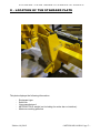
1
Serial N° : 09.13.288 METEOR MD110.R01 Translation of the original instructions User, assembly and spare parts manual Make sure to comply with the instruction for use Z.I. du Chail – 17800 PONS - Tél. 05.46.96.25.50 - Fax : 05.46.94.64.72 S.A.S. au capital de 100 000 € -R.C.S . SAINTES B 401 895 883 - SIRET 401 895 883 00023 - Code A.P.E.285 D S.A.S. COUP¨'ECO – Z.I. du Chail, 17800 PONS – Tél : 05.46.96.25.50 – Fax : 05.46.94.64.72 Edition 10/2013 ~ METEOR MD110.R01 Page 1 ~ S.A.S. COUP¨'ECO – Z.I. du Chail, 17800 PONS – Tél : 05.46.96.25.50 – Fax : 05.46.94.64.72 Table of contents I – EC Conformity for equipment to self-certification : .... Erreur ! Signet non défini. II – LOCATION OF THE STANDARD PLATE ............................................................. 5 III - FOREWORD ....................................................................................................... 6 IV - INTRODUCTION ................................................................................................ 7 V – EQUIPMENT DESCRIPTION ............................................................................... 8 5-1/ Specificity : .................................................................................................................................. 8 5-2/ Characteristics: ............................................................................................................................ 8 5-3/ Kinematics: .................................................................................................................................. 9 VI – SAFETY INSTRUCTIONS ................................................................................ 12 6-1/ Generals safety instructions : .................................................................................................... 12 6-2/ Compliance audit of the pruning machine before each start ..................................................... 12 6-3/ Prior inspection of work area ..................................................................................................... 12 6-4/ Work instructions ....................................................................................................................... 13 6-5/ Ground characteristics on which the tractor moves ................................................................... 13 6-6/ Safety on site: ........................................................................................................................... 14 6-7/ Maintenance guidelines ............................................................................................................. 15 VII - CONTRAINDICATIONS .................................................................................. 16 VIII- LABELS ON SAFETY ..................................................................................... 17 8-1/ Explanation of symbols pasted on the machine ........................................................................ 17 8-2/ Localization of the stickers on the machine ............................................................................... 18 8-3/ Meaning of the symbols in this manual ..................................................................................... 19 IX - INSTALLATION AND START-UP ..................................................................... 20 9-1/ Installation procedure : .............................................................................................................. 20 Hydraulic installation procedure........................................................................................................ 20 9-2/ Preliminary checks .................................................................................................................... 21 9-3/ How to get started: .................................................................................................................... 21 X- WORKING CONDITIONS.................................................................................... 23 10-1/ Moving the tractor with the pruning equipment: ....................................................................... 23 10-2/ Marking the site ....................................................................................................................... 23 10-3/ Inspection of the work area ..................................................................................................... 23 10-4/ Reminder of safety site personnel. .......................................................................................... 23 10-5/ Choice of cutting equipment .................................................................................................... 24 10-6/ Selecting the rotation of the cutting element: .......................................................................... 24 10-7/ How to act: .............................................................................................................................. 25 10-8/ Choosing the Forward Speed .................................................................................................. 27 10-9/ After Work ............................................................................................................................... 27 10-10/ Garaging equipment .............................................................................................................. 27 10-11/ Storage of the pruning equipment. ........................................................................................ 28 XI – ADVERSE EVENTS DURING WORK ................................................................ 29 11-1/ Blocking a saw blade in a large branch: .................................................................................. 29 11-2/ Jamming branches on the cutterbar: jam ................................................................................ 29 XII - MAINTENANCE AND ADJUSTMENT .............................................................. 30 12-1/ Lubrication ............................................................................................................................... 30 12-2/ Tightening torque for CL 8.8 screws ....................................................................................... 31 12-3/ Maintenance of the cutting element ........................................................................................ 31 XIII - GUARANTEE CONDITIONS........................................................................... 33 Edition 10/2013 ~ METEOR MD110.R01 Page 2 ~ S.A.S. COUP¨'ECO – Z.I. du Chail, 17800 PONS – Tél : 05.46.96.25.50 – Fax : 05.46.94.64.72 XIV - SPARE PARTS LIST ...................................................................................... 34 14-1/ General BOM .......................................................................................................................... 35 14-2/ Chassis 100 ............................................................................................................................ 37 14-3/ Harm 200 ................................................................................................................................ 38 14-4/ Cutter bar support 300 ............................................................................................................ 39 14-5/ Security system ....................................................................................................................... 40 14-6/ Cutter bar support 320 ............................................................................................................ 41 XV- HYDRAULIC DIAGRAM ................................................................................... 42 Edition 10/2013 ~ METEOR MD110.R01 Page 3 ~ S.A.S. COUP¨'ECO – Z.I. du Chail, 17800 PONS – Tél : 05.46.96.25.50 – Fax : 05.46.94.64.72 Edition 10/2013 ~ METEOR MD110.R01 Page 4 ~ S.A.S. COUP¨'ECO – Z.I. du Chail, 17800 PONS – Tél : 05.46.96.25.50 – Fax : 05.46.94.64.72 II – LOCATION OF THE STANDARD PLATE This plate displays the following information: - Equipment type. Serial No. Year manufactured. METEOR T90 R weight (not including the cutter bar or interface). Maximum working pressure Edition 10/2013 ~ METEOR MD110.R01 Page 5 ~ S.A.S. COUP¨'ECO – Z.I. du Chail, 17800 PONS – Tél : 05.46.96.25.50 – Fax : 05.46.94.64.72 III - FOREWORD All our equipment is fully studied carefully and manufactured with the best components, ensuring high reliability: - Hydraulic equipment with high quality, high performance and unquestionable reliability. - High performance motor providing high performance with long duration of life. - Blades machined from special steels conferring their resistance. - Knives receiving special sharpening and a heat treatment of high hardness. - Quality construction particularly well. Each device range is a highly professional tool tightly controlled and adapted to the most intense work. Before all, and before the first utilization of the equipment, users must thoroughly familiarize themselves with this installation and user manual to ensure proper equipment use. Edition 10/2013 ~ METEOR MD110.R01 Page 6 ~ S.A.S. COUP¨'ECO – Z.I. du Chail, 17800 PONS – Tél : 05.46.96.25.50 – Fax : 05.46.94.64.72 IV - INTRODUCTION You have just acquired your new METEOR MD110.R01 with the cutter bar 3500 or 4500. We appreciate your choice and hope it brings you all the satisfaction you've come to expect from a high-performance product. This user and spare parts manual will provide you with the information you need to: - achieve optimum conditions for use and benefit from all technical improvements that your equipment incorporates. - optimize operation through the recommendations for installation and use. strict observance of straightforward - to cope without loss of time, resolve minor problems that do not require the intervention of a specialist The moments you will spend reading this leaflet, will be largely offset by the teachings you will end up getting. If some points are still unclear, technicians at our service department will be happy to give you further information. Edition 10/2013 ~ METEOR MD110.R01 Page 7 ~ S.A.S. COUP¨'ECO – Z.I. du Chail, 17800 PONS – Tél : 05.46.96.25.50 – Fax : 05.46.94.64.72 V – EQUIPMENT DESCRIPTION The METEOR MD110.R01 has been designed to be fitted onto all types of carrying vehicle that conform to the recommended flow rate / pressure and feeding speed characteristics. Drill holes are provided on the chassis for hitching the METEOR MD110.R01. These holes are used to fit the various (optional) attachment interfaces specially designed for various carrying vehicle makes and models 5-1/ Specificity : The METEOR MD110.R01 is comprised of a chassis and a transfer arm which can be deployed on the right side with a manual lock in the deployed or retracted position. This equipment allows cutting on the right side, vertically or horizontally. The leveling and the transition from the vertical position to the horizontal position is effected through a hydraulic cylinder. A safety double system in the axle of the blade permits to protect the machine if the machine can’t cut some wood or if the saw blade is stuck in the tree. 5-2/ Characteristics: Version Weight of equipment Cutting lenght of the cutter bar Flow required for the hydraulic cylinder Pressure of the cylinder Flow required by the hydraulic motor Pressure of the motor Max pressure on the drain of the motor Filtering motor Hydraulic motor Transmission power Rotation speed of the blades Diameter of the blades Blade thickness Linear velocity MD110.R01.3500 MD110.R01.4500 220 Kg 240 Kg 1.20 m 1.60 m 4 to 10 l/min 180 bar 28 to 60 l/min 170 bar 3 bar 10 m 11 cc 12 CV 2500 rpm 500 mm 3 mm 65 m/s Serial equipment: Saw blades of diam. 500 mm. 96 lying teeth. Optional equipment: Simple knives discs. Reinforced knives discs. Directions for use : Discs : - cutting green wood : branches 25 mm, - dry cutting wood : branches 20 mm. Saw blade : cutting branches 5 to 100 mm. Edition 10/2013 ~ METEOR MD110.R01 Page 8 ~ S.A.S. COUP¨'ECO – Z.I. du Chail, 17800 PONS – Tél : 05.46.96.25.50 – Fax : 05.46.94.64.72 It is imperative to choose the cutting tool adapted to the work to be done. 5-3/ Kinematics: Version - Handling position : A : Offset relative to the axis of the tractor B : Total length MD110.R01 C : Length of the back of the machine hooking D : Length in front of the tractor attaching E : Height to the attachment pin F : Height relative to the attachment pin Edition 10/2013 MD110.R01.3500 MD110.R01.4500 1.30 m 2.00 m 0.35 m 0.60 m 0.55 m 0.70 m 1.10 m ~ METEOR MD110.R01 Page 9 ~ S.A.S. COUP¨'ECO – Z.I. du Chail, 17800 PONS – Tél : 05.46.96.25.50 – Fax : 05.46.94.64.72 - Deposit position : L : Length of the MD110.R01 deposed H : Height l : Width Edition 10/2013 MD110.R01.3500 MD110.R01.4500 2.00 m 1.25 m 1.60 m 0.95 m ~ METEOR MD110.R01 Page 10 ~ S.A.S. COUP¨'ECO – Z.I. du Chail, 17800 PONS – Tél : 05.46.96.25.50 – Fax : 05.46.94.64.72 - Vertical cut: Offset of the outside wheel Offset from the axis of the feeder H : Height of the cut of the cutter bar MD110.R01.3500 MD110.R01.4500 1.56 m 2.50 m 1.20 m 1.60 m - Horizontal cut: A : Maximal offset from the axis of the feeder B : Minimal offset to the wheel MD110.R01.3500 MD110.R01.4500 2.90 m 3.30 m 0.80 m Edition 10/2013 ~ METEOR MD110.R01 Page 11 ~ S.A.S. COUP¨'ECO – Z.I. du Chail, 17800 PONS – Tél : 05.46.96.25.50 – Fax : 05.46.94.64.72 VI – SAFETY INSTRUCTIONS 6-1/ Generals safety instructions : According the measures introduced by the Decree 93-41, driving this machine is strictly limited to trained personnel specifically designated. 6-2/ Compliance audit of the pruning machine before each start Always make sure that the nuts and bolts of the cutting element fixations are correctly tightened. Always check that the attachment of the equipment on the feeder pruning is done correctly and that the locking pin is in place. Always check the condition of the cutting element and perform its sharpening or replacement if necessary: state and swaging sharpening blades, no crack in the bottom of gorges, state of sharpening knives, play of knife bolt ... Always replace damaged knives as soon as you notice a vibration. Replacing in must be done in pairs, to maintain the balance of the plate. Always ensure the readability of all safety signs on the machine, clean and possibly replace if necessary. Always inspect hydraulic hoses and make sure there are no leaks. 6-3/ Prior inspection of work area Always carry out an inspection of the work area or the hedge to raise the presence of wire, steel studs, large stones, bottles and other dangerous objects. Remove these objects before starting the project. Always raise the obstacle presence elevated, especially power lines: in this case determine and report the driver category of rows and recall instructions In France: - For line voltage below 50 KV, the minimum working distance required is 3m. - For lines greater than 50 kV, the minimum working distance to meet voltage is 5m. Check local regulations. Edition 10/2013 ~ METEOR MD110.R01 Page 12 ~ S.A.S. COUP¨'ECO – Z.I. du Chail, 17800 PONS – Tél : 05.46.96.25.50 – Fax : 05.46.94.64.72 6-4/ Work instructions Always keep the third persons of the machine during the coupling or removal operations equipment: define a perimeter of 25 m. around the machine during these operations. Always enforce the safety area demarcated around the machine according to the cutter bar used (see cutter bar user manual). - 25m of the machine to prevent his overthrow. - 50m around the machine to prevent projections for site personnel - 100m in the working axis of the blades to prevent the projections. Always ensure that staff dedicated to collecting branches or otherwise, is equipped with the appropriate personal protective equipment. Always ensure that staff dedicated to collecting branches observe and enforce the security perimeter. Always stop the blades when making operations without cutting: movement of the arm, moving backwards, positioning the cutter bar Always adjust the feed rate to the terrain on which the tractor operates. Always put the blade guard in place by the end the project, or after stopping the feeder. Always clean the cutting equipment at the end of each working day: remove the branches and leaves and accumulation of sawdust. Always fold the pruning equipment in transport position at stopping and when moving off work.. 6-5/ Ground characteristics on which the tractor moves It is imperative to respect the maximum slope and superelevation indicated in the instructions allowed the feeder. Failure to do so may cause the overthrow the feeder. To work safely, the feeder must move on a hard, stable and regular ground with a slope less than 10% and whose slope is less than 5 °. More the working height is important, the speed of the tractor must be slow. Edition 10/2013 ~ METEOR MD110.R01 Page 13 ~ S.A.S. COUP¨'ECO – Z.I. du Chail, 17800 PONS – Tél : 05.46.96.25.50 – Fax : 05.46.94.64.72 6-6/ Safety on site: When working with the cutter bar, there is a risk of projections, falling branches and crop residue, and more particularly in the space located in the axis of the cutter bar. To avoid these risks, it is necessary to prevent any person from entering a security zone lying in the axis of the cutter bar: For the vertical cut, the security area is a long strip of 100 m to 100 m ahead and to the rear of the cutter bar and the width of which is at least 25 meters on each side of the machine. For the horizontal cut, the safety zone is a circle of 110m radius around the feeder. Pedestrians, cyclists, site personnel: For site personnel, always wear personal protective equipment (helmet, gloves, glasses ...), the security zone in the axis of the cutter bar is reduced to 50m. to the rear of the cutter bar. Apart from site personnel, it is necessary to ensure that there was no other person in sight (pedestrians, cyclists ...) in an area within a radius of 100m around the cutterbar for vertical work, in addition to the security zone being in the axis of the cutter bar as defined above. If people are in these areas, the operator must temporarily stop working, as long as these people leave the area. Vehicles in movement : In addition to the safety zone in the axis of the cutter bar, be sure to define an additional area beyond which other vehicles are allowed. This area of movement is opposite to the cut at a distance of 1m50 from the outer of the wheels. If the width of the road does not allow it, it is imperative that the operator stops working when crossing with another vehicle. During any maneuver in reverse, it is imperative to stop the rotation of the cutter bar. Edition 10/2013 ~ METEOR MD110.R01 Page 14 ~ S.A.S. COUP¨'ECO – Z.I. du Chail, 17800 PONS – Tél : 05.46.96.25.50 – Fax : 05.46.94.64.72 6-7/ Maintenance guidelines Always position the machine and pruning equipment on a firm ground in an open area to perform all maintenance operations. Always provide personal protective equipment to maintenance operations * Gloves, safety shoes, protective glasses Always cut the power and energy supply of the feeder and the auxiliary group. Activate the parking brake before working on the equipment pruning. * Stop the engines * Activate the circuit breaker. Always observe, in addition to the recommendations presented in this manual, all general standards of safety. Always involve a specialized technician for all interventions other than described in this manual. Always keep a good sharpening of the saw blades. Always observe scrupulously the procedure described in this manual and the manual of the cutter bar for the disassembly and reassembly of the saw blades. Always thoroughly clean pruning equipment at the end of workday. Always replace worn or defective parts with original parts. Edition 10/2013 ~ METEOR MD110.R01 Page 15 ~ S.A.S. COUP¨'ECO – Z.I. du Chail, 17800 PONS – Tél : 05.46.96.25.50 – Fax : 05.46.94.64.72 VII - CONTRAINDICATIONS Never allow non-accredited and not trained persons to use this equipment pruning. Never use this equipment pruning or the machine under the influence of alcohol. Never use the pruning equipment without demarcate the markup site. Never use the pruning equipment by strong wind : max: 40 km / h (10 m / s) Never stand under the arms of the feeder or under the pruning equipment when they are high. Do not continue to use the cutter bar when a wire or other stringy material is wound around a bearing. Never drive on the road without installing the housing protections blades. Never use a blade that is not cutting any more. Never cut large branches with the cutter bar when the blades are not parallel to the direction of movement of the wearer. Never cut branches larger than the size recommended in this manual (see'' usage recommendation "page 8). Never use the pruning equipment without the casing rear protection. Never use the pruning equipment without the lower shoe. Never overhanging a traffic area without having prohibits the access. Never perform maintenance not described in this operations manual. Never use pruning equipment during the night or if the brightness does not allow the operator to clearly see the end of the cutter bar. Never use the pruning equipment as a means of lifting people or objects. Do not use the equipment to push cut branches. Never leave the saw blades rotate during maneuvers with the tractor without pruning operation (change street, moving in reverse …). Edition 10/2013 ~ METEOR MD110.R01 Page 16 ~ S.A.S. COUP¨'ECO – Z.I. du Chail, 17800 PONS – Tél : 05.46.96.25.50 – Fax : 05.46.94.64.72 VIII- LABELS ON SAFETY 8-1/ Explanation of symbols pasted on the machine ROTATING TOOLS: Objects and debris can be thrown. Maintain a safe distance from the cutter bar. E1 (Ref. 25.550.002) RISK OF CUTS: The blades are sharp tools. Caution! Caution ! During their handling and during the cutting (Ref. 012866 and 25.550.029) E2 Helmet and goggles are required in the work area. (Ref. 25.550.017) E3 Edition 10/2013 ~ METEOR MD110.R01 Page 17 ~ S.A.S. COUP¨'ECO – Z.I. du Chail, 17800 PONS – Tél : 05.46.96.25.50 – Fax : 05.46.94.64.72 8-2/ Localization of the stickers on the machine On pruning equipment are arranged icons stickers that must be kept in good condition and replaced when they aren’t visible any more. Edition 10/2013 ~ METEOR MD110.R01 Page 18 ~ S.A.S. COUP¨'ECO – Z.I. du Chail, 17800 PONS – Tél : 05.46.96.25.50 – Fax : 05.46.94.64.72 8-3/ Meaning of the symbols in this manual DANGER CAUTION WARNING This symbol is used to draw your attention to the safety and the proper operation of your machine: It is necessary to observe all the safety measures mentioned. Wearing protective gloves Required Port safety shoes obligatory Wear a safety helmet, Wear an Auditive protection Wear eye protection obligatory Edition 10/2013 ~ METEOR MD110.R01 Page 19 ~ S.A.S. COUP¨'ECO – Z.I. du Chail, 17800 PONS – Tél : 05.46.96.25.50 – Fax : 05.46.94.64.72 IX - INSTALLATION AND START-UP 9-1/ Installation procedure : Mechanical installation of the equipment. Position the tractor and the pruning equipment on a firm ground in an open area to perform all operations. You have to use the attachment interface for coupling the saw head cutting system (see “Device description”). Make sure the device is properly attached and it’s not likely to come off. Hydraulic installation procedure You have connect the hoses of supply and return from the flow rate regulator with the couplers of your tractor.. Connect the hose of the drain to your tractor. Connect the hoses of the hydraulic cylinder to your tractor. P If the tractor allows it (if the pressure is less than 3b in the return), you can connect the drain in the return in the T (Rep1). Edition 10/2013 ~ METEOR MD110.R01 Page 20 ~ S.A.S. COUP¨'ECO – Z.I. du Chail, 17800 PONS – Tél : 05.46.96.25.50 – Fax : 05.46.94.64.72 9-2/ Preliminary checks - Check the hydraulic oil level - Check the conformity of the pruning equipment 9-3/ How to get started: Positioning the cutter bar: - Remove the pin handle ring 1, extend the cutter bar in the cutting position and lock the position by resetting the pin in the ring 2. Edition 10/2013 ~ METEOR MD110.R01 Page 21 ~ S.A.S. COUP¨'ECO – Z.I. du Chail, 17800 PONS – Tél : 05.46.96.25.50 – Fax : 05.46.94.64.72 - Deploy the cutter bar in the desired cutting position using the dual effect of the tractor flow. Starting the cutter bar: - Make sure that nothing and no one is located close the blades - Switch on the motor of the cutter bar by operating the single tractor flow - Make turn the equipment during 5 mn to average mode, in order to put oil and the transmission in temperature (blades with 1500 rpm). - Accelerate the engine will allow saw blades or discs have the good speed for pruning the branches. Edition 10/2013 ~ METEOR MD110.R01 Page 22 ~ S.A.S. COUP¨'ECO – Z.I. du Chail, 17800 PONS – Tél : 05.46.96.25.50 – Fax : 05.46.94.64.72 X- WORKING CONDITIONS 10-1/ Moving the tractor with the pruning equipment: During all road trips, the cutter bar must be positioned at the left, in transport position (see p.9), the harm should be folded, and the guard blades (item 1) must be positioned on the saws. 1 10-2/ Marking the site Before starting cutting branches, it is mandatory to mark the site to prohibit access to the work area. See « work instructions » page 13 10-3/ Inspection of the work area Before you start cutting branches, check the condition of the soil, and control that no foreign objects is situated in the hedge or tree Cf “Safety instructions” page 12. Recording the location of poles and obstacles. Make sure of the size of branches (diameter) to use the right cutting tool. 10-4/ Reminder of safety site personnel. Cf safety instructions pages 12 à 14 - Port of Personal protective equipment - Compliance with safety distances - Enforce the security perimeter Edition 10/2013 ~ METEOR MD110.R01 Page 23 ~ S.A.S. COUP¨'ECO – Z.I. du Chail, 17800 PONS – Tél : 05.46.96.25.50 – Fax : 05.46.94.64.72 10-5/ Choice of cutting equipment Originally, the cutter bar receives blades 500 mm diameter. These saws can cut branches from 5 mm to 100 mm in diameter. Optionally, it is possible to mount trays knives (also called knives). They are designed to cut shoots up to 25 mm in diameter. Saw blade 500 Knives disc Attention choosing the right cutting tool and maintenance are very important and necessary to ensure quality work but also and especially for your safety and the safety of users CAUTION: The use of knives plates is strictly prohibited to work in large timber (diameter greater than 25 mm branch) because it can be dangerous. 10-6/ Selecting the rotation of the cutting element: - For vertical cutting, the blades and plates must cut in an upward direction for the best cutting quality. If you want to minimize the projection of cut wood, it is better to rotate the cutting element down Note: The saw blade cuts only in one direction Make sure it is fitted in the correct direction compared to the direction of rotation. The flail plate is equipped with knives with 2 cutting sides: you can reverse the direction of rotation without changing the direction of fitting. - For horizontal cutting, the blades and plates must rotate in such a way that debris is thrown away from the user. Our general recommendation is to box in the cabin for protection against flying debris and falling branches. Edition 10/2013 ~ METEOR MD110.R01 Page 24 ~ S.A.S. COUP¨'ECO – Z.I. du Chail, 17800 PONS – Tél : 05.46.96.25.50 – Fax : 05.46.94.64.72 10-7/ How to act: The MD110.R01 only cut in the right side of the tractor. Never use the pruning equipment by strong wind : max: 40 km / h (10 m / s) The tractor will be used advancing to do alignments. For vertical cutting: to the height allowed by the manufacturer of the tractor. For horizontal cutting: to the height allowed by the manufacturer of the tractor. In these configurations, the size of the branches to be cut should not exceed 100 mm. in saw blades and less than 25 mm rotary flails. To work safely, it is imperative to be on a hard surface, stable and regular with the slope is less than 10% and which the inclination is less than 5 °. It is preferable to start working from the bottom: the vegetation will then drop away vertically from the cut Horizontal cutting Vertical cutting . Working procedure: At the beginning of alignment, put the tractor in a position to advance in parallel alignment. Put your head cutter in the desired position (horizontal or vertical), then start working. * During use, we recommend the following precautions if the blades become entangled in the branches: Edition 10/2013 ~ METEOR MD110.R01 Page 25 ~ S.A.S. COUP¨'ECO – Z.I. du Chail, 17800 PONS – Tél : 05.46.96.25.50 – Fax : 05.46.94.64.72 - Keep the tractor on course - Do not try to correct the reach or height of the verge cutter arm. - Set your speed according to the size of the branches. * When cutting thick branches, the tractor must be kept as far away as possible to avoid any damage to it. We recommend cutting thick branches in several stages. * If the blades jam you must: - stop the hedge cutter - extract all the equipment by moving the tractor out rather than retracting the arm or changing the cutting angle. The maximum working heights are defined in the charts issued by the manufacturer of the tractor (or this dealer) Reminder of how to use: Working at ground level is strictly forbidden. Never use pruning equipment during the night or if the brightness does not allow the operator to clearly see the end of the cutter bar. Never leave the saw blades rotate during maneuvers with the tractor without pruning operation (change street, moving in reverse …). Edition 10/2013 ~ METEOR MD110.R01 Page 26 ~ S.A.S. COUP¨'ECO – Z.I. du Chail, 17800 PONS – Tél : 05.46.96.25.50 – Fax : 05.46.94.64.72 10-8/ Choosing the Forward Speed The forward speed depends on the type of vegetation and its density. It also depends on the condition of the terrain over which the tractor is moving. For denser vegetation with larger branches the forward speed must be slower. Similarly, the forward speed must be reduced over uneven terrain. In general, we recommend a forward speed of 1 to 2 kph. 10-9/ After Work Before switching off the hedge cutter, it should be left to run for 5 minutes with the blades facing upwards so that the roller bearing at the top of the bearing block is well lubricated. Before switching off the motor, it is essential to reduce the power take-off speed to the minimum. Only then can the motor power supply be switched off. Clean equipment by removing the branches and twigs stuck in the various joints. Then fold the equipment in transport position. 10-10/ Garaging equipment Put the legs and lock them with the locking pin. To be lifted, the pruning equipment must be in its folded position, with the blade guard in place. The positioning cylinder must be retracted. The shoe of the cutter bar has to touch the ground. Position the tractor and the pruning equipment on a firm ground, with a good access for the tractor. Edition 10/2013 ~ METEOR MD110.R01 Page 27 ~ S.A.S. COUP¨'ECO – Z.I. du Chail, 17800 PONS – Tél : 05.46.96.25.50 – Fax : 05.46.94.64.72 How stall : - Disconnect couplings - Disconnect the equipment tractor - Slowly reverse the tractor 10-11/ Storage of the pruning equipment. The storage of this equipment should be done on a flat, stable ground, away from moisture. The blade guard must be positioned Before storing equipment the pruning for a long time without use, it is important to thoroughly clean, grease all joints and greasing the bearings of the cutter bar. For the rod of the tilt cylinder which remains in the extended position, all chrome portion should be coated slightly with naval grease to prevent its oxidation. Also you can coat the surfaces of the two blades with a thin layer of oil storage using a small spray or a cloth to protect against corrosion. Edition 10/2013 ~ METEOR MD110.R01 Page 28 ~ S.A.S. COUP¨'ECO – Z.I. du Chail, 17800 PONS – Tél : 05.46.96.25.50 – Fax : 05.46.94.64.72 XI – ADVERSE EVENTS DURING WORK During the pruning you may be faced with different situations that may cause a malfunction of the equipment or blocking. 11-1/ Blocking a saw blade in a large branch: - STOP the advancement of the tractor - stop the hedge cutter - extract all the equipment by moving the tractor out rather than retracting the arm or changing the cutting angle. - Once the blade disengaged, re-start the engine of the cutter bar (thermal engine at idle) and accelerate the engine 11-2/ Jamming branches on the cutterbar: jam - stop the hedge cutter - put the cutting equipment at ground level with the cutter bar in a vertical position, reached at the level by a man on the ground floor, and on a flat floor, stable and clear - operate the parking brake and stop the tractor's engine - put the personal protective equipment: gloves, goggles - remove branches stuck with hands rotating blades (with your hand) if necessary. Edition 10/2013 ~ METEOR MD110.R01 Page 29 ~ S.A.S. COUP¨'ECO – Z.I. du Chail, 17800 PONS – Tél : 05.46.96.25.50 – Fax : 05.46.94.64.72 XII - MAINTENANCE AND ADJUSTMENT 12-1/ Lubrication - All the bearings are greased during assembly at the factory for a period of 150 hours. - Greasing frequency: every 100 hours of operation. - Quantity of grease: 18 grams per bearing (3 pump strokes). - Approved grease: IGOL Rally GREASE with synthetic agents (420g pack) - Use the grease gun designed for the purpose. - The bearings should be greased with the equipment in the vertical position. - Whenever work (maintenance, disassembly and reassembly) is carried out on the blades or rotary flails, apply grease to thread of the nuts securing the plates. Bearing’s lubrication : Edition 10/2013 Remove the safety screw (vis de securite) Remove the lock washer (Washer de sécurité) Install the oiler M8 instead (graisseur M8) ~ METEOR MD110.R01 Page 30 ~ S.A.S. COUP¨'ECO – Z.I. du Chail, 17800 PONS – Tél : 05.46.96.25.50 – Fax : 05.46.94.64.72 12-2/ Tightening torque for CL 8.8 screws Screw M6 Screw M8 Screw M10 Screw M12 Screw M14 Screw M16 Screw ½ (flail screw) Nuts M24x150 (grooved wheel nut) Clamping nut blades 0.81 m/kg 1.94 m/kg 3.87 m/kg 6.75 m/kg 10.8 m/kg 16.8 m/kg 11 m/kg 18 m/kg 70 m/kg 12-3/ Maintenance of the cutting element All manipulations blades or flails trays must be done with gloves and the operator must be equipped with safety shoes. Refer to the manual of the cutterbar Sharpening Flail Cutters: The condition of the flails should therefore be checked every day, - replacing them if they are damaged (deep notches) or sharpening them if the cutting edge is marked. - you have reached the max allowed on sharpening the knife: Measure the width of the knife to the closest location. If the width is less than 36 mm, replace the knife When changing the knives, it is imperative to change both knives on the plate at the same time not to unbalance it. Edition 10/2013 ~ METEOR MD110.R01 Page 31 ~ S.A.S. COUP¨'ECO – Z.I. du Chail, 17800 PONS – Tél : 05.46.96.25.50 – Fax : 05.46.94.64.72 It is imperative to replace the bolts at each change of knives with knives Rep. 2, 3 and 4 Caution : fit the knive in the correct orientation The mark should be outside the flail plate A well-sharpened cutter will make a cleaner cut and will have a longer life. Edition 10/2013 ~ METEOR MD110.R01 Page 32 ~ S.A.S. COUP¨'ECO – Z.I. du Chail, 17800 PONS – Tél : 05.46.96.25.50 – Fax : 05.46.94.64.72 XIII - GUARANTEE CONDITIONS - The guarantee provided by COUP’ECO is for a duration of 1 (one) year from the date that the equipment is made available at our factory. It only covers manufacturing defects confirmed by our own examination and only commits us to dispatching parts for those recognised as being faulty (excluding labour) and without liability to pay compensation for down-time. - Faulty assemblies or subassemblies must be returned to the after-sales service within 8 days of the incident, accompanied by a guarantee request: Complete and not dismantled for a STANDARD REPLACEMENT request Complete and not dismantled for a GUARANTEE request - Carriage and packing costs for faulty parts, as well as new parts replaced under guarantee will be entirely at the buyer's expense. - Repair or replacement of parts during the guarantee period does not extend its period of validity. - All faulty parts replaced by a new part remain the property of COUP’ECO. - The seller shall not be liable to pay compensation to the buyer for damage suffered, such as: - Personal injuries, - Damage to goods other than those covered by the contract. - The guarantee does not cover everyday wearing parts such as blades, cutters, hoses, etc. or parts damaged accidentally or as the result of inadequate maintenance or failure to follow equipment operating instructions. - The guarantee expires: - If replacements or repairs are made by third parties or the buyer himself, without the seller's written consent, - If parts fitted by the constructor are replaced by parts from a different source, - If equipment is modified or transformed in any way by any person. - We reserve the right to make any modifications to our models that we consider necessary, without being under obligation to make these modifications on equipment already delivered. - In the event of disputes concerning the supply or payment for it, the Commercial Court of SAINTES is the only competent court, regardless of conditions of sales and means of payment accepted, even if the dispute concerns the guarantee or if there are several defendants. - By express agreement, we remain the owner of delivered goods until they are fully paid for, under the terms of Law No. 80.335 of 12 May 1980. Edition 10/2013 ~ METEOR MD110.R01 Page 33 ~ S.A.S. COUP¨'ECO – Z.I. du Chail, 17800 PONS – Tél : 05.46.96.25.50 – Fax : 05.46.94.64.72 XIV - SPARE PARTS LIST Whenever maintenance work is carried out on the hedge cutter, it is essential to contact us to avoid any wrong actions. For top performance, use COUP’ECO spare parts. This will give users the benefit of the latest developments. Buy your spare parts from the COUP’ECO original part constructor via your importer or regional approved dealer. Always mention the type of machine, serial number and part reference number. Developments made by our company may result in modifications to some parts mentioned in this manual. We always supply the most recent part if it is interchangeable with the previous model. Please contact us for any additional information you require and also for special studies or products. The constructor disclaims all responsibility if the equipment is used in a manner contrary to the recommendations made in this manual. The user must observe general hygiene and safety rules. Other measures may be required in addition to our advice and safety rules. Edition 10/2013 ~ METEOR MD110.R01 Page 34 ~ S.A.S. COUP¨'ECO – Z.I. du Chail, 17800 PONS – Tél : 05.46.96.25.50 – Fax : 05.46.94.64.72 REFERENCE DESIGNATION MARK QTY 1 2 3 4 5 6 7 8 9 10 11 12 13 14 15 1 1 1 1 1 1 1 1 1 1 1 1 1 1 2 14-1/ General BOM MD110.R01.100C MD110.R01.200C MD110.R01.300C MD110.R01.320C Chassis 100 Harm 200 Support lamier 300 Support lamier 320 Cutting system BAP.19.162 20.701.3 Pin handle Ø19 Lg.157 mm Hydraulic cylinder 25x40 C300 Security system Protection blades MD110.R01.120 MD110.R01.212 MD110.R01.330 MD110.R01.340 MD110.R01.350 MD110.R01.400 Axis 120 Axis 212 Axis 330 Axis 340 Axis 350 Leg Edition 10/2013 ~ METEOR MD110.R01 Page 35 ~ S.A.S. COUP¨'ECO – Z.I. du Chail, 17800 PONS – Tél : 05.46.96.25.50 – Fax : 05.46.94.64.72 Edition 10/2013 ~ METEOR MD110.R01 Page 36 ~ S.A.S. COUP¨'ECO – Z.I. du Chail, 17800 PONS – Tél : 05.46.96.25.50 – Fax : 05.46.94.64.72 REFERENCE DESIGNATION MARK QTY 14-2/ Chassis 100 MD110.R01.100 20.560.102 25.550.001 MD110.R01.120 MD110.R01.119 ROND.050.009.08 21.080.707 21.075.609 21.075.700 21.075.702 21.036.529 Edition 10/2013 Chassis 100 Flow rate regulator Standard plate CE Coup'Eco Axis 120 Gliding piece Washer Ø 50 x 9 x 8 SCREW TFHC 5x10 Screw , HEX SKT HEAD M 6 x 70 Screw , HEX SKT HEAD M 8 x 16 Screw , HEX SKT HEAD M 8 x 25 Contact washerØ8 1 2 3 4 5 6 7 8 9 10 11 ~ METEOR MD110.R01 Page 37 ~ 1 1 1 1 1 1 4 2 1 1 3 S.A.S. COUP¨'ECO – Z.I. du Chail, 17800 PONS – Tél : 05.46.96.25.50 – Fax : 05.46.94.64.72 REFERENCE DESIGNATION MARK QTY 14-3/ Harm 200 MD110.R01.200 MD110.R01.212 ROND.035.009.06 21.075.700 21.036.529 21.075.702 Edition 10/2013 Harm 200 Axis 212 Washer Ø 35 x 09 x 6 Screw , HEX SKT HEAD M 8 x 16 Contact washerØ8 Screw , HEX SKT HEAD M 8 x 25 1 2 3 4 5 6 ~ METEOR MD110.R01 Page 38 ~ 1 1 1 1 2 1 S.A.S. COUP¨'ECO – Z.I. du Chail, 17800 PONS – Tél : 05.46.96.25.50 – Fax : 05.46.94.64.72 REFERENCE DESIGNATION MARK QTY 14-4/ Cutter bar support 300 MD110.R01.300 MD110.R01.330 MD110.R01.340 MD110.R01.350 ROND.035.009.06 ROND.050.011.08 21.075.702 21.036.529 21.075.700 21.075.703 Edition 10/2013 Cutter bar support 300 Axis 330 Axis 340 Axis 350 Washer Ø 35 x 09 x 6 Washer Ø 50 x 11 x 8 Screw , HEX SKT HEAD M 8 x 25 Contact washerØ8 Screw , HEX SKT HEAD M 8 x 16 Screw , HEX SKT HEAD M 8 x 30 1 2 3 4 5 6 7 8 9 10 ~ METEOR MD110.R01 Page 39 ~ 1 1 1 1 2 1 2 6 3 1 S.A.S. COUP¨'ECO – Z.I. du Chail, 17800 PONS – Tél : 05.46.96.25.50 – Fax : 05.46.94.64.72 REFERENCE DESIGNATION MARK QTY 14-5/ Security system MD110.R01.381 MD110.R01.390 MD110.R01.396 21.150.270.80.13 21.026.507 Edition 10/2013 Axis Washer ressort Spring guide Compression spring 80x270 threaded rod M14 L=380mm + fork threaded rod M14 Locknut M14 1 2 3 4 5 6 7 ~ METEOR MD110.R01 Page 40 ~ 2 4 2 2 2 2 8 S.A.S. COUP¨'ECO – Z.I. du Chail, 17800 PONS – Tél : 05.46.96.25.50 – Fax : 05.46.94.64.72 REFERENCE DESIGNATION MARK QTY 14-6/ Cutter bar support 320 14.067.011 MD110.R01.320 21.031.503 21.067.811 Edition 10/2013 Close sheet for tube 70mm Cutter bar support 320 Washer grower 10 SCREW HEXAGONAL 10x40 1 2 3 4 ~ METEOR MD110.R01 Page 41 ~ 1 1 6 6 S.A.S. COUP¨'ECO – Z.I. du Chail, 17800 PONS – Tél : 05.46.96.25.50 – Fax : 05.46.94.64.72 XV- HYDRAULIC DIAGRAM Edition 10/2013 ~ METEOR MD110.R01 Page 42 ~