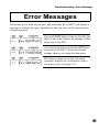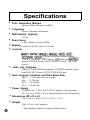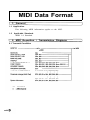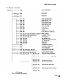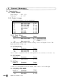
1
YAMAHA
®
AUTHORIZED
PRODUCT MANUAL
TONE GENERATOR
TONE GENERATOR
Owner’s Manual
YAMAHA
FCC INFORMATION (U.S.A.)
IMPORTANT NOTICE: DO NOT MODIFY THIS UNIT!
This product, when installed as indicated in the instructions contained in this manual,
meets FCC requirements. Modifications not expressly approved by Yamaha may void your
authority, granted by the FCC, to use the product.
IMPORTANT:
When connecting this product to accessories and/or another product use only high quality
shielded cables. Cable/s supplied with this product MUST be used. Follow all installation
instructions. Failure to follow instructions could void your FCC authorization to use this
product in the USA.
NOTE:
This product has been tested and found to comply with the requirements listed in FCC
Regulations, Part 15 for Class “B” digital devices. Compliance with these requirements
provides a reasonable level of assurance that your use of this product in a residential
environment will not result in harmful interference with other electronic devices. This
equipment generates/uses radio frequencies and, if not installed and used according to the
instructions found in the user’s manual, may cause interference harmful to the operation of
other electronic devices. Compliance with FCC regulations does not guarantee that
interference will not occur in all installations. If this product is found to be the source of
interference, which can be determined by turning the unit “OFF” and “ON”, please try to
eliminate the problem by using one of the following measures:
Relocate either this product or the device that is being affected by the interference.
Utilize power outlets that are on different branch (circuit breaker or fuse) circuits or
install AC line filter/s.
In the case of radio or TV interference, relocate/reorient the antenna. If the antenna
lead-in is 300 ohm ribbon lead, change the lead-in to co-axial type cable.
If these corrective measures do not produce satisfactory results, please contact the local
retailer authorized to distribute this type of product. If you can not locate the appropriate,
please contact Yamaha Corporation of America, Electronic Service Division, 6600
Orangethorpe Ave. Buena Park CA, 90620
This applies only to products distributed by Yamaha Corporation of America.
CANADA
THIS DIGITAL APPARATUS DOES NOT EXCEED THE “CLASS B” LIMITS FOR RADIO NOISE
EMISSIONS FROM DIGITAL APPARATUS SET OUT IN THE RADIO INTERFERENCE
REGULATION OF THE CANADIAN DEPARTMENT OF COMMUNICATIONS.
LE PRESENT APPAREIL NUMERIQUE N’EMET PAS DE BRUITS RADIOELECTRIQUES
DEPASSANT LES LIMITES APPLICABLES AUX APPAREILS NUMERIQUES DE LA “CLASSE
B” PRESCRITES DANS LE REGLEMENT SUR LE BROUILLAGE RADIOELECTRIQUE EDICTE
PAR LE MINISTERE DES COMMUNICATIONS DU CANADA.
* This applies only to products distributed by Yamaha Canada Music LTD.
* Ceci ne s’applique qu’aux produits distribués par Yamaha Canada Music LTD.
Wichtiger Hinweis für die Benutzung in der Bundesrepublik Deutschland.
Bescheinigung des lmporteurs
Hiermit wird bescheinigt, da der/die/das
Tone Generator Typ: MU5
(Gerät, typ, Bezeichnung)
in Übereinstimmung mit den Bestimmungen der
VERFÜGUNG 1046/84
(Amtsblattverfügung)
funk-entstört ist.
Der Deutschen Bundespost wurde das lnverkehrbringen dieses Gerätes angezeigt und
die Berechtigung zur Überprüfung der Serie auf Einhaltung der Bestimmungen
eingeräumt.
Yamaha Europa GmbH
Name des Importeurs.
•
•
•
•
This applies only to products distributed by Yamaha Europa GmbH.
Dies bezicht sich nur auf die von der Yamaha Europa GmbH Vertriebenen Produkte.
Ceci ne s’applique qu’aux produits distribués par Yamaha Europa GmbH.
EStO se aplica solamente a productos distoribuidos por Yamaha Europa GmbH.
Dit produkt is gefabriceerd in overeenstemming met de
radiostoringsvoorschriften van de Richtlijn van de Raad
(82/499/EEG).
Este produto está de acordo com o radio de interferencia
frequente requiridos do Conselho Directivo 82/499/EEC.
Dette apparat overholder det gaeldende EF-direktiv
verdrørende radiostøj.
Cet appareil est conforme aux prescriptions de la
directive communautaire 87/308/CEE.
Diese Geräte entsprechen der EG-Richtlinie 82/499/EWG
und/oder 87/308/EWG.
This product complies with the radio frequency
interference requirements of the Council Directive 82/
499/EEC and/or 87/308/EEC.
Questo apparecchio è conforme al D.M.13 aprile 1989
(Direttiva CEE/87/308) sulla soppressione dei
radiodisturbi.
Este producto está de acuerdo con los requisitos sobre
interferencias de radio frequencia fijados por el Consejo
Directivo 87/308/CEE.
YAMAHA CORPORATION
Entsorgung leerer
Batterien
(nur innerhalb
Deutschlands)
Leisten Sie einen Beitrag zum
Umweltschutz. Verbrauchte
Batterien oder Akkumulatoren
dürfen nicht in den Hausmüll.
Sie können bei einer
Sammelstelle für Altbatterien
bzw. Sondermüll abgegeben
werden. lnformieren Sie sich
bei lhrer Kommune.
The serial number of this
product may be found on the
bottom of the unit. You should
note this serial number in the
space provided below and
retain this manual as a
permanent record of your
purchase to aid identification
in the event of theft.
Model No.
Serial No.
MU5
SPECIAL MESSAGE SECTION (U.S.A.)
This product utilizes batteries or an external
power supply (adapter). DO NOT connect
this product to any power supply or adapter
other than one described in the manual, on
the name plate, or specifically recommended by Yamaha.
This product should be used only with the
components supplied or; a cart, rack, or
stand that is recommended by Yamaha. If a
cart, etc., is used, please observe all safety
markings and instructions that accompany
the accessory product.
SPECIFICATIONS SUBJECT TO CHANGE:
The information contained in this manual is
believed to be correct at the time of
printing. However, Yamaha reserves the
right to change or modify any of the
specifications without notice or obligation to
update existing units.
This product, either alone or in combination
with an amplifier and headphones or
speaker/s, may be capable of producing
sound levels that could cause permanent
hearing loss. DO NOT operate for long
periods of time at a high volume level or at
a level that is uncomfortable. If you
experience any hearing loss or ringing in
the ears, you should consult an audiologist.
IMPORTANT: The louder the sound, the
shorter the time period before damage
occurs.
NOTICE:
Service charges incurred due to lack of
knowledge relating to how a function or
effect works (when the unit is operating’ as
designed) are not covered by the manufacturer’s warranty, and are therefone the
owners responsibility. Please study this
manual carefully and consult your dealer
before requesting service.
ENVIRONMENTAL ISSUES:
Yamaha strives to produce products that
are both user safe and environmentally
friendly. We sincerely believe that our
products and the production methods used
to produce them, meet these goals. In
keeping with both the letter and the spirit of
the law, we want you to be aware of the
following:
Battery Notice:
This product MAY contain a small nonrechargeable battery which (if applicable) is
soldered in place. The average life span’ of
this type of battery is approximately five
years. When replacement becomes necessary, contact a qualified service representative to perform the replacement.
This product may also use “household” type
batteries. Some of these may be rechargeable. Make sure that the battery being
charged is a rechargeable type and that the
charger is intended for the battery being
charged.
When installing batteries, do not mix old
batteries with new, or with batteries of a
different type. Batteries MUST be installed
correctly. Mismatches or incorrect installation may result in overheating and battery
case rupture.
Warning:
Do not attempt to disassemble, or incinerate any battery. Keep all batteries away
from children. Dispose of used batteries
promptly and as regulated by the laws in
your area. Note: Check with any retailer of
household type batteries in your area for
battery disposal information.
Disposal Notice:
Should this product become damaged
beyond repair, or for some reason its
useful life is considered to be at an end,
please observe all local, state, and federal
regulations that relate to the disposal of
products that contain lead, batteries,
plastics, etc. If your dealer is unable to
assist you, please contact Yamaha directly.
NAME PLATE LOCATION:
The name plate is located on the bottom of
the product. The model number, serial
number, power requirements, etc., are
located on this plate. You should record the
model number, serial number, and the date
of purchase in the spaces provided below
and retain this manual as a permanent
record of your purchase.
Model
MU5
Serial No.
Purchase Date
92-BP
PLEASE KEEP THIS MANUAL
Welcome to the MU5
Congratulations and thank you for purchasing the Yamaha MU5 Tone
Generator!
The MU5 is an advanced tone generator providing exceptionally
high-quality Voices, full General MIDI compatibility, and
flexible computer interfacing in a highly compact and portable
package.
With the built-in host computer interface and MIDI terminals,
the MU5 is ideal for any computer music system — from connection to a simple laptop to integration in a complete MIDI studio.
It even features a two-octave keyboard (with adjustable tenoctave range), allowing you to play the internal Voices and enter
notes to a connected sequencer. And, since it runs on batteries as
well, it’s ready to make music wherever you take it.
n
Trademarks
• Apple and Macintosh are trademarks of Apple Computer, Inc.
• IBM PC and PC/AT are registered trademarks of International Business
Machines Corporation.
• PC-9800 series are trademarks of NEC Corporation.
All other trademarks are the property of their respective holders.
Table of Contents
Welcome to the MU5 . . . . . . . . . . . . . . . . . . . . . . . . . . . . . . . . . . . 1
How to Use This Manual . . . . . . . . . . . . . . . . . . . . . . . . . . . . . . . . 4
Precautions . . . . . . . . . . . . . . . . . . . . . . . . . . . . . . . . . . . . . . . . . . 6
The Controls of the MU5 . . . . . . . . . . . . . . . . . . . . . . . . . . . . . . 8
n FrontPanel . . . . . . . . . . . . . . . . . . . . . . . . . . . . . . . . . . . 8
n Rear Panel . . . . . . . . . . . . . . . . . . . . . . . . . . . . . . . . . . . 10
n Side Panel . . . . . . . . . . . . . . . . . . . . . . . . . . . . . . . . . . . 10
The MU5 - What It Is and What lt Can Do . . . . . . . . . . . . . . . . . 11
Setting Up Your MU5 . . . . . . . . . . . . . . . . . . . . . . . . . . . . . . . . . . 14
n Power Supply . . . . . . . . . . . . . . . . . . . . . . . . . . . . . . . . .14
Using a Power Adaptor . . . . . . . . . . . . . . . . . . . . 14
Using Batteries . . . . . . . . . . . . . . . . . . . . . . . . . . . 15
When to Replace the Batteries . . . . . . . . . . . . . . 15
n Audio Connections . . . . . . . . . . . . . . . . . . . . . . . . . . . . . 16
Using Headphones . . . . . . . . . . . . . . . . . . . . . . . 16
Using an External Sound System . . . . . . . . . . . . 16
Setting Up the MU5 in Your Music System . . . . . . . . . . . . . . . . . 17
n Connecting With a Computer . . . . . . . . . . . . . . . . . . . . . 17
Macintosh . . . . . . . . . . . . . . . . . . . . . . . . . . . . . . . 18
IBM PC and Clones . . . . . . . . . . . . . . . . . . . . . . . 19
NEC PC-9800 Series . . . . . . . . . . . . . . . . . . . . . . 20
n Connecting to Other MIDI Devices . . . . . . . . . . . . . . . . 20
n Data Flow Block Diagram . . . . . . . . . . . . . . . . . . . . . . . 21
n MIDI/Computer Connecting Cables . . . . . . . . . . . . . . . . 22
Playing the Demo Song . . . . . . . . . . . . . . . . . . . . . . . . . . . . . . . . 23
Using the MU5 — The Play Mode . . . . . . . . . . . . . . . . . . . . . . . . 24
n Playing the Keyboard . . . . . . . . . . . . . . . . . . . . . . . . . . . 24
n Changing the Octave Setting . . . . . . . . . . . . . . . . . . . . . 25
n Selecting a Part and Changing the Voice . . . . . . . . . . .26
Using the MU5 with a Computer or Sequencer . . . . . . . . . . . . . . 28
Using the MU5 with a MIDI Data Storage Device . . . . . . . . . . . . 28
Muting and Soloing Parts . . . . . . . . . . . . . . . . . . . . . . . . . . . . . . . 29
Editing . . . . . . . . . . . . . . . . . . . . . . . . . . . . . . . . . . . . . . . . . . . . 30
Table of Contents
Reference . . . . . . . . . . . . . . . . . . . . . . . . . . . . . . . . . . . . . . 3 2
Utility Mode . . . . . . . . . . . . . . . . . . . . . . . . . . . . . . . . . . . . . . . . . 32
• Master Tune . . . . . . . . . . . . . . . . . . . . . . . . . . . . . 32
• Transpose . . . . . . . . . . . . . . . . . . . . . . . . . . . . . 33
• Mute Lock . . . . . . . . . . . . . . . . . . . . . . . . . . . . . . 33
• Velocity . . . . . . . . . . . . . . . . . . . . . . . . . . . . . . . 34
• Local Control . . . . . . . . . . . . . . . . . . . . . . . . . . . . 35
• Dump Out . . . . . . . . . . . . . . . . . . . . . . . . . . . . . 36
• Initialize All . . . . . . . . . . . . . . . . . . . . . . . . . . . . .38
Part Edit Mode . . . . . . . . . . . . . . . . . . . . . . . . . . . . . . . . . . . . . 39
• Volume . . . . . . . . . . . . . . . . . . . . . . . . . . . . . 39
• Pan . . . . . . . . . . . . . . . . . . . . . . . . . . . . . . . . . . . . 4 0
• MIDI Channel . . . . . . . . . . . . . . . . . . . . . . . . . . . . 4 0
• Note Shift . . . . . . . . . . . . . . . . . . . . . . . . . . . . . . 41
• Part Tune . . . . . . . . . . . . . . . . . . . . . . . . . . . . .41
• Pitch Bend Range . . . . . . . . . . . . . . . . . . . . . . .42
Appendix . . . . . . . . . . . . . . . . . . . . . . . . . . . . . . . . . . . . . . 4 3
Troubleshooting . . . . . . . . . . . . . . . . . . . . . . . . . . . . . . . . . . . . 43
Error Messages . . . . . . . . . . . . . . . . . . . . . . . . . . . . . . . . . . . . 45
Specifications . . . . . . . . . . . . . . . . . . . . . . . . . . . . . . . . . . . . 46
Index . . . . . . . . . . . . . . . . . . . . . . . . . . . . . . . . . . . . . . . . . . . . 47
Voice List . . . . . . . . . . . . . . . . . . . . . . . . . . . . . . . . . . . . . . . add-2
MIDI Data Format . . . . . . . . . . . . . . . . . . . . . . . . . . . . . . . . . add-8
MIDI Implementation Chart . . . . . . . . . . . . . . . . . . . . . . . . . .add-24
How to Use This Manual
You are probably eager to try out your new MU5 Tone Generator right away
and hear what it can do, rather than have to read through a lot of instructions
before you can even get a sound out of it.
However, to get the most out of your MU5, we strongly suggest that you read
the following sections in the order given:
1) Precautions
This gives you important information on how to care for your
new MU5, how to avoid damaging, and how to ensure long-term,
reliable operation.
2) The MU5 — What It Is and What It Can Do
This briefly provides an overview of the functions and features of
the MU5 and offers some important hints on how you can use it
effectively.
3) Setting Up Your MU5; The Controls of the MU5
The first section shows you how to set up your MU5 for basic
operation, and the second introduces you to the panel controls
and connectors.
4) Playing the Demo Song; Using the MU5 — The Play Mode
These two sections get you started using the MU5. The first
guides you through the Demo Song, while the second gives you
the basic operation procedures you’ll be using when you play the
MU5.
5) Setting Up the MU5 in Your Music System; Using the MU5
with a Computer or Sequencer
These sections provide all you need to know to effectively
integrate the MU5 into your present computer music system.
How to Use This Manual
6) Muting and Soloing Parts; Editing
Mute and Solo are useful in song playback, while editing operations prepare you for digging. in deeper to the advanced functions
of the MU5.
7) Reference
Once you’re familiar with everything above, lightly go over this
comprehensive guide to all editing functions. You won’t need (or
want) to read everything at once, but it is there for you to refer to
when you need information about a certain feature or function.
8) Appendix
Finally, use the sections in the Appendix as necessary. For
example, the Index will come in handy when you need to quickly
find information on a specific topic. Other sections, such as the
Voice List, Troubleshooting and Error Messages provide
additional useful information.
Precautions
Your MU5 will give you years of reliable service if you follow the simple
precautions below:
•
LOCATION
Keep the instrument away from locations where it is likely to be
exposed to high temperatures (such as direct sunlight) or humidity. Also avoid locations which are subject to excessive dust
accumulation or vibration which could cause mechanical damage.
•
USE THE CORRECT POWER ADAPTOR
Use only the recommended PA-3, PA-4 or PA-40 Power Adaptor
for supplying power to the instrument. Use of another adaptor
may cause serious damage to the instrument or the adaptor itself.
•
MAKE SURE POWER IS OFF WHEN MAKING OR
REMOVING CONNECTIONS
To prevent damage to the instrument and other connected equipment, always turn off the power prior to connecting or disconnecting cables. Also, turn the power off when the instrument is
not in use, and disconnect the power adaptor during electric
storms.
l HANDLE THE INSTRUMENT WITH CARE
Although the instrument has been constructed to withstand the
rigors of normal use for optimum sturdiness and reliability, avoid
subjecting it to strong physical shocks (such as dropping or
hitting it). Since the MU5 is a precision-made electronic device,
also avoid applying excessive force to the various controls.
When moving the instrument, first unplug the power adaptor and
all other cables to prevent damage to cords and jacks. Always
unplug cables by gripping the plug firmly, not by pulling on the
cable.
Precautions
•
CLEAN WITH A SOFT, DRY CLOTH
Never use solvents such as benzine or thinner to clean the instrument, since these will damage the cabinet finish or dull the keys.
Wipe clean with a soft, dry cloth. If necessary, use a soft, clean,
slightly moistened cloth — making sure to wipe the case off
again with a dry cloth.
•
ELECTROMAGNETIC INTERFERENCE
Avoid using the unit near televisions, radios or other equipment
generating electromagnetic fields. Proximity to such equipment
may cause the unit to malfunction, and may generate interference
noise in the other appliance as well.
•
DO NOT OPEN THE CASE OR TRY REPAIRING
THE INSTRUMENT YOURSELF
The instrument contains no user-serviceable parts. Never open
the case or tamper with the internal circuitry in any way, since
doing so may result in damage to the instrument. Refer all
servicing to qualified Yamaha service personnel.
•
MIDI CABLES
When connecting the instrument to other MIDI equipment, be
sure to use only high-quality cables made especially for MIDI
data transmission. Also, avoid using cables longer than 15
meters, since long cables can result in data errors.
Yamaha is not responsible for damage caused by improper handling or
operation.
The Controls of the MU5
n Front Panel
Display
In the Play mode, this shows the Part number and the currently
selected program number and Voice name for the Part. It also
shows the octave setting (when set to a value other than normal)
and acts as a “level meter,” showing the velocity values for each
Part as they are played.
In the Edit modes, this shows the relevant values and, where
applicable, a graphic display of the set values.
buttons
For selecting the desired Part. (In some of the Edit functions,
these may not be available.) Hold down either button to rapidly
advance through the values.
The Controls of the MU5
buttons
For changing the value of the selected function or parameter. In
the Play mode, these are used to change the program number at
the selected Part. In the Edit modes, these are used to change the
current function’s value or turn a function on or off. Hold down
either button to rapidly advance through the values.
button
For using the Mute and Solo functions. (See page 29.)
button
For leaving the Edit modes and returning to the Play mode.
(OCTAVE DOWN) and
(OCTAVE UP) buttons
For changing the octave transposition of the MU5's keyboard.
These also double as
buttons, allowing you to select the
functions of the Edit modes.
Keyboard
This two-octave keyboard is used to play the Voices of the MU5.
It can also be used to play notes on a connected external tone
generator or enter notes to a connected sequencer or computer.
The white keys double as editing controls, while the black keys
buttons.)
also function as number keys. (Used with the
button
For switching between positive (+) and negative (-) values during
editing. (Used with the
buttons.)
button
For actually entering values during editing. (Used with the
buttons.)
n Rear Panel
MIDI OUT and MIDI IN terminals
For connection to other MIDI devices, such as a MIDI keyboard,
tone generator, sequencer, or to a computer that has a MIDI
interface. (See page 20.)
HOST SELECT switch
For selecting the type of connected device. (See pages 17 - 20.)
TO HOST terminal
For connection to a host computer that does not have a MIDI
interface. (See pages 17 - 20.)
DC IN jack
For connection to the AC power adaptor.
POWER switch
For turning on the power to the unit.
n Side Panel
VOLUME control
For adjusting the overall level of the MU5
LINE OUT/PHONES jack
For connection to an amplifier/speaker system or a set of stereo
headphones.
The MU5 — What It Is and What It Can Do
The MU5 -What It Is and What It Can Do
n What It Is...
The MU5 is a compact, highly portable and easy-to-use tone generator. It
features full General MIDI Level 1 compatibility with 128 General MIDI
Voices and 8 drum kits. The MU5 has 28-Voice polyphony and is 16-Part
multi-timbral. In other words, the MU5 has 16 different Parts, each with its
own Voice, so that up to 16 different Voices can be sounded simultaneously.
With the built-in two-octave keyboard, you can play any of the Voices directly
from the MU5 itself. Or you can play them from a connected MIDI keyboard.
In addition, the MU5 also has a TO HOST terminal for easy interfacing with a
computer, allowing you to play the Voices using your favorite music software.
This is where the advanced multi-timbral capabilities come in, letting you play
up to 16 different Voices at the same time.
n
About General MIDI
General MIDI is a new addition to the worldwide MIDI standard. MIDI, as
you know, stands for Musical Instrument Digital Interface, and makes it
possible for various electronic musical instruments and other devices to
“communicate” with each other. For example, by connecting a sequencer to
the MU5’s MIDI IN terminal, you could play back a song on the sequencer
using the Voices of the MU5.
So, where does General MIDI fit in all of this? One of the most important
features of General MIDI is in the standardization of Voices. This means that
a song recorded in the General MIDI format can be played back on any General MIDI compatible tone generator and sound just as the composer intended.
For example, if there is an alto sax solo in the song, it will be played by an alto
sax Voice on the General MIDI tone generator (and not by a tuba or harpsichord!). Since the MU5 is fully compatible with General MIDI, you can take
advantage of the vast wealth of musical material recorded in that format.
n What It Can Do...
Here are a few ideas on how you can use the MU5. The list below is not
comprehensive, but is meant to be a general guide to the possibilities and
provide a starting point or springboard for your own creative ideas and explorations.
•
Using With MIDI Keyboard
Use the MU5 as supplementary tone generator with your MIDI
keyboard and play the Voices of both instruments in a layer
together. Or, if your keyboard has the capability, program a
“split” so that the notes you play on the right side of the keyboard
play only the Voices of the MU5.
•
Using With Other MIDI Controllers
Even if you’re not a keyboard player, you can still play the MU5
with other types of MIDI controllers. For example, you can use a
MIDI percussion controller to play the drum and percussion
sounds of the MU5.
n When Connected to a Computer or
Sequencer
•
Home Studio Setup
The MU5 integrates easily into any existing setup. If you have a
MIDI keyboard, computer and sequencing software, the MU5
with its high-quality Voices and multi-timbral capabilities can
expand your home studio system.
•
Carry It With You
If you have a laptop computer (and sequencing software), simply
connect the MU5, plug in some headphones and you’ve got a
complete music making system that’s ready to go wherever you
go. Use it for composing, arranging, practicing or making/
playing demos for your band.
The MU5 — What It Is and What It Can Do
•
Perform With It
Bring it with you to a gig — as long as there’s a MIDI keyboard
on stage, you can use the high-quality sounds of MU5 in your
performance.
•
Multimedia
Since it’s portable and compatible with General MIDI, the MU5
is a natural for multimedia applications. Bring it with you to a
presentation — since the computer interface is built-in to the
MU5, it hooks up instantly and easily to the computer’s serial
port or printer port, without the need for any other equipment.
n
About the Modes of the MU5
The MU5 has three operating modes: Play, Utility and Part Edit.
(Utility and Part Edit are the two edit-related modes of the MU5.)
•
Play Mode
This is the normal mode of the MU5, the one in which you
normally play and select the internal Voices (either from the
built-in keyboard or a connected MIDI device), select Parts, and
use the Mute and Solo functions.
•
Utility Mode
The Utility mode lets you set functions related to the overall
operation of the MU5, such as Master Tune, Transpose and
Velocity settings. Included also are utility operations, such as
sending bulk data to a data storage device, and initializing of the
MU5 settings.
•
Part Edit Mode
The Part Edit mode allows you to change certain settings for each
individual Part, such as the Volume, Pan and individual tuning
settings for each Part. The internal Voices can be sounded during
editing, allowing you to hear the effects of your edits.
Setting Up Your MU5
n
Power Supply
Your MU5 will run either from an optional AC adaptor or batteries. Follow
the instructions below according to the power source you intend to use.
Before making any connections, make sure that all equipment to
be connected is turned off.
•
Using a Power Adaptor
Connect one end of the power adaptor (Yamaha PA-3, PA-4 or
PA-40) to the DC IN jack on the rear panel, and the other end to
a suitable electrical outlet.
adaptor
n Do not attempt to use an AC adaptor other than
the PA-3, PA-4 or PA-40. The use of an incompatible adaptor may result in irreparable damage to the
MU5, and even pose a serious shock hazard.
n Be sure to disconnect the power adaptor from the
outlet when the MU5 is not in use.
Setting Up Your MU5
l Using Batteries
To use the MU5 on battery power, insert six 1.5V AA size
(SUM-3, R-6 or equivalent) manganese or alkaline batteries in
the battery compartment. Make sure to follow the polarity
indications on the bottom case (and as shown below).
Securely replace the battery compartment cover when done
installing the batteries.
l When to Replace the Batteries
When the battery power runs too low to operate the MU5, the
following display will appear:
When this happens, replace all batteries with a complete set of six
new batteries of the same type.
In order to avoid losing any important memory
settings when battery power becomes low, turn off
the MU5, then immediately connect a power
adaptor (to supply continuous power) and replace
all batteries.
NEVER mix old and new batteries or different
types of batteries! Also, to prevent possible damage due to battery leakage, remove the batteries
from the instrument if it is not to be used for an
extended period of time.
Audio Connections
In order to hear your MU5, you’ll have to make certain audio connections.
You can listen to the MU5 by using a set of stereo headphones or by connecting it to an amplifier/speaker system.
l Using Headphones
Connect a set of stereo headphones (with a stereo miniature plug)
to the LINE OUT/PHONES jack.
l Using an External Sound System
Connect the LINE OUT/PHONES jack on the MU5 to the stereo
inputs of an amplifier/speaker system by using a “Y” cable
(stereo miniature plug to dual RCA pin plugs), available from
many audio and musical instrument dealers.
Setting Up the MU5 in Your Music System
Setting Up the MU5 in Your Music System
As you learned in the section The MU5 — What It Is and What It Can Do
on page 11, the MU5 can be integrated into a variety of setups. It would be
impossible to cover all connection possibilities in a short manual as this;
however, the section below will help in quickly setting up the MU5 and using
it in your system.
Connecting With a Computer
The MU5 features a built-in host computer interface, allowing you to directly
connect it to your computer — eliminating the need of installing a special
MIDI interface to your computer. The MU5 can be used with the following
computers: Apple Macintosh, IBM PC and the NEC PC-9800 Series.
If your computer has a MIDI interface you may want to connect the MU5 to it,
rather than using the host computer interface on the MU5. (See the section
“Connecting to Other MIDI Devices” on page 20.)
Depending on the computer or interface used, set the HOST SELECT switch
to the appropriate setting: MIDI, PC-l (NEC computers), PC-2 (IBM and
clones), or MAC (Macintosh). For information on the types of cables that can
be used for connection, see the section “MIDI/Computer Connecting
Cables” on page 22.
Follow these instructions if you have an Apple Macintosh that is
not equipped with an external MIDI interface. Connect the TO
HOST terminal on the MU5 to the Modem or Printer port on the
Macintosh.
1
Set the HOST SELECT switch to MAC.
2
Connect the MU5 to the host computer, as shown in the
illustration above. Use a standard Macintosh cable (8-pin
Mini DIN on both ends; see page 22).
3
Turn on the host computer. then the MU5.
4
Start up your music software, and set up the appropriate
options on the software for operation with the MU5.
l
The options you may have to set include:
Standard MIDI Interface
l MIDI Interface Type
Off
l MIDI Time Piece
1 MHz
l Clock
Other options and settings may have to be made as well. Refer to
the owner’s manual of your particular music software for more
information.
Setting Up the MU5 in Your Music System
Follow these instructions if you have an IBM PC/AT or compatible computer that is not equipped with an external MIDI interface. Connect the TO HOST terminal on the MU5 to one of the
computer’s serial ports, COM 1 or COM 2.
Your music software must be able to recognize
the TO HOST connection. Consult your Yamaha
dealer for more details. If your software is not
compatible, you can still use the MU5 by installing a
MIDI interface (internal card or external) to the
computer.
1
Set the HOST SELECT switch to PC-2.
2
Connect the MU5 to the host computer, as shown in the
illustration above. Use a standard computer cable (8-pin
Mini DIN to 9-pin D-SUB; see page 22).
3
Turn on the host computer, then the MU5.
4
Start up your music software, and set up the appropriate
options on the software for operation with the MU5.
Refer to the owner’s manual of your particular music software for
more information.
The NEC PC-9800 Series computers are widely used in Japan.
For use with these computers, set the HOST SELECT switch on
the MU5 to PC-1. Operation is the same as for
the PC-2 setting explained above. The only
difference between PC-l and PC-2 is the
communication baud rate. (See page 46.)
Connecting to Other MIDI Devices
The MU5 is equipped with MIDI IN and OUT terminals, allowing you to use it
in any MIDI system. Example uses for the built-in MIDI interface include:
• Connecting to a MIDI keyboard (for playing the sounds of the MU5
from that keyboard).
• Connecting to a MIDI tone generator (for playing the sounds of that
tone generator from the MU5).
• Connecting to a computer equipped with a MIDI interface (either
internal or external).
• Connecting to a hardware sequencer (such as the Yamaha QY20).
• Connecting to a MIDI data storage device (such as the Yamaha MDF2
MIDI Data Filer).
Setting Up the MU5 in Your Music System
1
Set the HOST SELECT switch to MIDI.
2
Connect the MU5 to the appropriate MIDI device, as shown
in the illustrations above. Use a standard MIDI cable (see
page 22).
3
Turn on the connected device, then the MU5.
4
If you are using a computer, start up your music software,
and set up the appropriate options on the software for operation with the MU5.
Data Flow Block Diagram
l When
l
HOST SELECT switch is set to MIDI:
When HOST SELECT switch is set to Mac, PC-1 or PC-2:
* When Local Control is set to Off, the keyboard of the MU5
cannot be used to play the internal AWM Voices. (See page
35.)
MIDI/Computer Connecting Cables
l
MIDI
l
Macintosh Apple Macintosh Peripheral cable (M0197). Maximum length 2 meters.
l
PC-1
8-pin MINI DIN to D-SUB 25-pin cable. If your PC-1 type computer has a
9-pin serial port, use the PC-2 type cable. Maximum length 1.8 meters.
l
PC-2
8-pin MINI DIN to D-SUB 9-pin cable. Maximum length 1.8 meters.
Standard MIDI cable. Maximum length 15 meters.
Playing the Demo Song
Playing the Demo Song
Now that you’ve set everything up properly, try playing the built-in Demo
Song. This showcases the high-quality Voices and the AWM tone generation
system of the MU5.
1
Simultaneously hold down the
The
button.
2
buttons and press
Simultaneously hold down the
button again to start the song.
the
buttons and press
3 The Demo Song starts playing immediately and repeats
indefinitely until stopped (in step 4 below). Playback of the
individual Parts of the song is shown graphically by the
“level meter” bars in the display.
During Demo Song playback, all panel controls
(except the
button and the VOLUME control)
cannot be used.
4
To stop playback of the song, press the
button.
5 To exit from the Demo Song function, press the
again.
button
Using the MU5 — The Play Mode
Now that you’ve heard the sophisticated capabilities of the MU5, try playing
with some of them yourself in the Play mode.
button, the Play
When you turn on the power of the MU5 or press the
mode is automatically called up. In this mode, you can select any of the 16
Parts for playing, and select which Voice is played in each Part.
Playing the Keyboard
The built-in two-octave keyboard allows you to play the Voices
directly from the MU5 itself, without having to use an external
keyboard. Since what you play on the keyboard is also transmitted via MIDI (or the TO HOST terminals), you can also play an
external tone generator or enter notes to a sequencer.
As you play the keyboard, notice the bars that appear in the
display at the current Part. These serve as a kind of “level
meter,” like those found on a mixing console or tape recorder,
indicating the level (or velocity) of the Voice at the corresponding Part.
Using the MU5 — The Play Mode
The velocity of the keyboard is fixed; in other words, each note
you play sounds at a predetermined volume. You can change this
velocity setting from the Velocity parameter in the Utility mode.
(See page 34.)
Changing the Octave Setting
Though the keyboard itself is two octaves, you can actually play
the MU5 over a ten-octave range. To do this use the
(OCTAVE UP) buttons. Press
(OCTAVE DOWN) and
button
to
lower
the
pitch by an octave, and press
the
the
button to raise it by an octave. The current octave
setting is shown in the display. (No indication appears when the
octave setting is normal.)
Selecting a Part and Changing the Voice
Now, let’s select a different Part and change its Voice.
1
buttons to select Part 2. (If Part 1 is shown in
Use the
button once.)
the display, simply press the
A total of 16 Parts are available, and each is shown in the
display.
2
Use the
buttons to select program number 12,
“Vibes.” (You can also use the number keys on the keyboard
to select a Voice; see boxed section on the next page.)
You can rapidly advance to the desired number
by briefly holding down the appropriate
button.
The MU5 has a total of 128 Voices, plus 8 different drum
kits. An “OFF” setting (a value of 137, or higher) is also
available for turning off the selected Part. (See page add-2
for a list of the available Voices.)
Using the MU5 — The Play Mode
Using the Number Keys to Select a Voice
In the Play mode, you can also use the number keys to select a
Voice’s program number.
To do this, simultaneously hold down the
buttons and
press the number of the value you wish to set. For example, to
set a value of 47, simultaneously hold down the
buttons and press
, then
, and finally press the
button to actually enter the new value.
Using the MU5 with a Computer or Sequencer
By connecting the MU5 to a computer or sequencer, you have a powerful
music system for playing back songs and even and creating your own songs,
using the Voices of the MU5.
Make sure that the MU5 is properly connected to the computer or sequencer,
and that your music software is ready to run. (Refer to pages 17 – 21 for
connection examples and instructions.) If you are using the TO HOST
terminal or if both MIDI terminals are properly connected, you should be able
to play songs from your software and enter notes to the software from the
MU5.
Using the MU5 with a MIDI Data Storage Device
You can also use the MU5 with a MIDI data storage device, such as the
Yamaha MDF2 MIDI Data Filer. This lets you save or back up whatever
changes you’ve made in the settings of the Utility and Part Edit modes. Then,
when you want to recall those settings, you can transfer the appropriate data
from the storage device.
The MDF2 also allows you to play compatible song data on the MU5 directly
from the MDF2 itself, without the need of a sequencer.
Make sure that the MU5 is properly connected to the data storage device (via
MIDI). (Refer to page 20 for the connection example.) Use the Dump Out
function (page 36) to send data to the device. Also refer to the owner’s manual
of your data storage device for specific operating instructions in receiving or
sending data.
Using the MU5 with a Computer or Sequencer /
Using the MU5 with a MIDI Data Storage Device / Muting and Soloing Parts
Muting and Soloing Parts
While a song is playing back on your computer or sequencer, you can selectively mute or solo any of the 16 Parts of the MU5. Mute lets you silence one
Part to hear how all of the other Parts sound without it. Solo lets you isolate a
single Part, to hear how that Part sounds by itself.
Mute and Solo are effective tools that help you as you edit the Parts, since they
allow you to better hear how the changes you make affect specific Voices as
well as the overall sound.
During playback, press the
button. Each press cycles
through the three functions: Mute, Solo and Normal operation.
Editing
The editing features of the MU5 provide various controls for changing the
Parts and setting other important operating functions. Among other things,
these let you set the Volume or pitch of each Part independently, change the
Velocity of the built-in keyboard, and save all of your edits to a connected
computer, sequencer or data storage device.
The MU5 has two edit modes: Utility and Part Edit. The Utility mode functions are related to the overall operation of the MU5, while the Part Edit mode
provides independent controls for each Part. (See the Reference section of this
manual for information about the specific editing functions.)
1
buttons and press
Simultaneously hold down the
the white key on the keyboard corresponding to the function
you wish to edit.
2
(For Part Edit only:) Use the
you wish to edit.
3
You can change the value or setting in two different ways:
l Use the
buttons to select the Part
buttons.
Editing
l Use the number keys on the keyboard.
buttons, press the number
While holding down the
of the value you wish to set. For example, to set a value of
buttons and press
47, simultaneously hold down the
button to
and finally press the
, then
actually enter the new value.
While holding this down, press
the following buttons in order:
If you try to enter an “illegal” value — a number
outside the range of the parameter — the MU5
enters the closest value to the one you’ve typed in.
For example in the Volume parameter, the range of
the parameter is 1 - 127, and if you try to enter 356,
the MU5 automatically enters 127.
4
button to return to the Play mode, or repeat
Press the
the steps above to edit another function.
EXIT
This concludes our short tour of the basic setup and general operations
of the MU5. Now that you’ve learned how to operate your MU5, look
through the Reference section that follows for more detailed information on the Utility and Part Edit modes.
Reference
Utility Mode
The Utility mode lets you set functions related to the overall operation of the
MU5, such as Master Tune, Transpose and Velocity settings. Included also are
utility operations, such as sending bulk data to a data storage device, and
initializing of the MU5 settings.
Master Tune
This determines the overall fine tuning of the MU5’S Voices. It
also affects the pitch of the individual drum/percussion sounds of
the drum kits. Master Tune is especially useful for adjusting the
pitch of the MU5 when playing with other instruments. (The
actual pitch of each Voice depends also on the other pitch related
parameters: Transpose, Note Shift and Part Tune.)
At around 440 Hz, 1 Hz is approximately equal to
4 cents.
Utility Mode
Transpose
This determines the overall key transposition of the MU5’s
Voices, over a total range of four octaves in semitone steps. A
Transpose setting of “0” results in normal pitch. Unlike Master
Tune, it has no effect on the individual drum/percussion sounds
of the drum kits.
Mute Lock
This determines whether or not the Part Mute status of the MU5
is reset when receiving a GM Mode On message. Generally, this
message is automatically transmitted to the MU5 as part of
General MIDI song data. When Mute Lock is off, this resets the
Mute status of the Parts on the MU5. If you want to keep the
current Mute settings and disable this reset, set Mute Lock to On.
(For more information on the Mute function, see page 29.)
Velocity
This determines the note on velocity of the built-in keyboard. All
notes that you play from the MU5’s keyboard will be at this fixed
velocity, and sound at the same level. This velocity is also
transmitted to connected devices via the MIDI or TO HOST
terminals. However, this does not affect the incoming velocity of
notes played from a connected sequencer or external keyboard.
Keep in mind that when playing the MU5’s
keyboard, the actual sound level of a Part also
depends on the Volume setting in the Part Edit
mode. If the Volume setting is at or near the
minimum, the Part may be very low in level, no
matter what the Velocity setting made here.
Utility Mode
Local Control
This determines whether or not the internal tone generator
responds to the notes you play on the MU5’s keyboard. Setting
this to Off effectively disconnects the MU5 keyboard from the
internal tone generator. However, notes played on the keyboard
are still transmitted via the TO HOST or MIDI OUT terminals.
One useful application of Local Control is when
you’ve connected the MU5 to another tone generator and want to play only that tone generator and
leave the MU5 Voices silent.
A more common application would be when using
the MU5 keyboard to input notes to a sequencer. If
the sequencer is also set up to play back data using
the Voices of the MU5, when you play the MU5, it
will be sounding its own voices twice — once from
the keyboard, and after a very brief delay, again
from the MIDI data coming from the sequencer.
This not only decreases the available polyphony of
the MU5 by half, but also creates an undesirable
flanging sound. To remedy the problem, set Local
Control to Off.
Dump Out
Not available
device number setting
(see boxed section on page 37).
1 – 16, All
All
This function allows you to save the current parameter settings of
the MU5 to a MIDI sequencer, computer or a MIDI data recorder
(such as the Yamaha MDF2 MIDI Data Filer).
•
Saving & Restoring Data via MIDI
Bulk Dump data can be
sent and received using
the MIDI IN and MIDI OUT
connections.
l Saving & Restoring Data via TO HOST
Bulk Dump data can be
sent and received using
the TO HOST connection.
Utility Mode
1
Make sure that the MU5 is properly connected to the
device and that the HOST SELECT switch is properly set.
When using the MIDI teminals; connect the MIDI OUT of
the MU5 to the MIDI IN of the data recorder. See the
Saving & Restoring Data via MIDI illustration above.)
Also, set the HOST SELECT switch to MIDI.
When using the TO HOST terminal, make sure that the
HOST SELECT switch is set corresponding to the device to
be used. (Refer to pages 17 – 21 for more on host computer
connections.)
2
Simultaneously hold down the
buttons and press
A “Sending” message appears in the display during the
operation. Once started, the operation cannot be stopped.
When the operation is completed, the MU5 returns to the
normal Play mode.
n Setting the Device Number
The settings allow you to select the device number specified for the data dump. if you are using more than one
MU5, set a different device number (1 – 16) for each unit
before sending the data. If you have only one MU5, set this
to ALL.
When using the number keys to enter a value for device
number, the value “0” corresponds to “ALL.”
To reload the data from the data recorder back to the MU5:
Make sure that the devices are properly connected (see the
Saving & Restoring Data via MIDI illustrations above); and
execute the appropriate data transfer operation from the data
recorder. (Refer to the owner’s manual of that device for instructions.) The MU5 automatically receives incoming bulk data.
Initialize All
This operation allows you to restore the original factory settings
of the MU5
n Using initialize All will erase whatever settings
you’ve made on the MU5 If you have important
settings you wish to keep, store them to a MIDI
data recorder with the Dump Out function. (See
page 36.)
Simultaneously hold down the
buttons and press
When the operation is completed, a “Finished” message appears
in the display and the MU5 returns to the normal Play mode.
Part Edit Mode
Part Edit Mode
The Part Edit mode allows you to change certain settings for each individual
Part. Keep in mind, though, that the settings you make may automatically
change when playing songs on a connected sequencer. For example, the song
data may include different Volume, Pan and Note Shift settings for each Part.
Volume
This determines the Volume of the selected Part. The Volume
setting is graphically represented by bars in the display.
Keep in mind that when playing the MU5's
keyboard, the actual sound level of a selected Part
also depends on the Velocity setting in the Utility
mode. If the Velocity setting is at or near the
minimum, the Part may be very low in level, no
matter what the Volume setting made here.
Pan
L64- C 00 - R 63
C 00
This determines the stereo position of a selected Part. The Pan
position is graphically represented by bars in the display. A
double bar (equal sign) in the middle represents the center
position (C 00), while a bar at the top indicates full right (R 63)
and a bar at the bottom indicates full left (L 64).
MIDI Channel
1 – 16, Off
Part 1 = 1, Part 2 = 2, Part 3 = 3, etc.
This determines the MIDI Receive Channel for each Part. For
example, if a Part is set to channel 1, it responds only to MIDI
data received over channel 1. For full multi-timbral operation, in
which each Part is used to play a different Voice, use the default
setting. (The "Off" setting can also be selected by using the
number key 0.)
Part Edit Mode
Note Shift
-24 – +24 semitones
00
This determines the key transposition (Note Shift) setting for
each Part. Keep in mind that the actual key transposition of the
Part also depends on the global Transpose setting in the Utility
menu (see page 33).
Part Tune
+/- 100 cents
0
This determines the fine tuning setting for each Part. It also
affects the pitch of the individual drum/percussion sounds of the
drum kits. Keep in mind that the actual pitch setting of the Part
also depends on the global Master Tune setting in the Utility
menu (see page 32).
Pitch Bend Range
-24 – +24 semitones
+02
This determines the maximum range over which the pitch of the
Part can be changed by Pitch Bend messages. Most MIDI
keyboards feature a Pitch Bend wheel, which allows you to
“bend” the pitch up or down as you play. Pitch Bend data can
also be recorded to a sequencer along with normal note data, and
then played back using the MU5.
The default setting (+02) allows you to continuously change the
pitch by a whole tone, up or down. Positive values raise the pitch
when you move the Pitch Bend wheel up, while negative values
lower the pitch when you move the wheel up.
Appendix
Troubleshooting
Even though the MU5 is exceptionally easy to use, it may occasionally not
function as you expect it to. If that happens, check the possible problems and
solutions below before assuming that the instrument is faulty.
Problem
Possible Cause and Solution
No power.
•
No sound.
•
If you are using an AC adaptor, check that the
adaptor is properly plugged into both the AC
outlet and the MU5 (See page 14.)
• If you are using batteries, check that a fresh set
of batteries are properly installed in the battery
compartment? (See page 15.)
Check that the side panel volume control is set
to an appropriate level. (See page 10.)
• Check that other volume-related parameters are
set to appropriate levels. (See Velocity, page
34, and Volume, page 39.)
• Check that the Parts being played are properly
turned on. (See page 26.)
• Check the Mute and Solo settings. (See page
29.) If a Part is being muted, or an empty Part
is being soloed, you may not get any sound.
Problem
Possible Cause and Solution
No sound when playing
the keyboard on the MU5.
•
Check that Local Control is set to on. (See page
35.) Also check the points for “No Sound”
above.
No sound when playing
the MU5 from a
computer, sequencer or
external keyboard.
•
Check all MIDI connections, making sure that
the MIDI OUT of the external device is connected to the MIDI IN of the MU5, and that the
MIDI IN of the external device is connected to
the MIDI OUT of the MU5. (See page 20.) Or,
if you are using the TO HOST terminal with a
computer, make sure that the terminal is properly connected to the computer and that the
HOST SELECT switch is properly set for your
particular computer. (See page 17.)
Notes are cut off or
omitted.
•
The maximum polyphony of the MU5 may be
exceeded. The MU5 can play no more than 28
notes at once.
When using a sequencer
or computer, an unusual
“flanging” sound occurs
and/or not all notes seem
to sound.
•
Check that Local Control is set to off. (See
page 35.) Also check the settings on your
sequencer or computer (such as “MIDI Echo” or
“Echo Back”).
Even though Local control
function is set to off, the
MU5 continues to sound
when playing the built in
keyboad.
•
This is nomal when routing the MU5 to a
sequencer (or computer) and the sequencer’s
“MIDI Echo” or “Echo Back” is set to on.
Troubleshooting / Error Messages
Error Messages
Errors may occur from time to time, and when they do the MU5 will display a
message to indicate the type of problem so that you can rectify it and return to
normal operation.
Too much MIDI data is being received by the
MU5 at one time. Reduce the amount of data
being sent to the MU5.
An error has been detected in the MIDI data
received by the MU5. Check all relevant
settings, then try receiving the data again.
The battery voltage is too low for proper
operation. Replace the old batteries with a
set of new ones. (See page 15.)
Specifications
•
Tone Generation Method
Advanced Wave Memory (AWM)
•
Polyphony
28-note (Dynamic allocation)
•
Multi-timbral Capacity
16-Part
•
Demo Song
1 (not editable, stored in ROM)
•
•
Display Custom LCD (54.5 mm x 29.4 mm)
Controls
, keypad (including number buttons,
UTILITY and PART EDIT buttons,
button and
button); POWER switch, HOST SELECT switch, VOLUME
control
•
Jacks and Terminals
MIDI OUT and MIDI IN terminals, TO HOST terminal (8-pin
mini DIN), DC IN jack, OUTPUT/PHONES jack
•
Host Computer Interface and Data Baud Rate
MIDI — 31,250 bps (bits per second)
Mac — 31,250 bps
PC-l — 31,250 bps
PC-2 — 38,400 bps
•
Power Supply
YAMAHA PA-3, PA-4 or PA-40 AC Adaptor (sold separately)
Six “AA” size, SUM-3, R-6 or equivalent batteries (sold separately)
•
Dimensions (W x D x H)
188 x 104 x 33 mm (7-3/8” x 4-1/8” x 1-1/3”)
•
Weight
340g (12 oz.) (w/o batteries)
* Specifications subject to change without notice.
Specifications / Index
Index
B
batteries, replacing . . . . . . . . . . .
batteries, using . . . . . . . . . . . . . . .
baud rate . . . . . . . . . . . . . . . . . .
Bend Range . . . . . . . . . . . . . . . .
15
15
46
42
C
computer, IBM . . . . . . . . . . . . . .
computer, Macintosh . . . . . . . . .
computer, NEC . . . . . . . . . . . . . .
connections, audio . . . . . . . . . . .
connections, MIDI . . . . . . . . . . .
19
18
20
16
20
D
Demo Song . . . . . . . . . . . . . . . . . 23
Dump Out . . . . . . . . . . . . . . . . . . 36
E
editing . . . . . . . . . . . . . . . . . . . . . 30
G
General MIDI . . . . . . . . . . . . . . . . 11
H
headphones . . . . . . . . . . . . . . . .
16
I
Initialize All . . . . . . . . . . . . . . . . 3 8
L
Local Control . . . . . . . . . . . . . . . 3 5
M
Master Tune . . . . . . . . . . . . . . . . 32
MIDI . . . . . . . . . . . . . . . . . . . l l
MIDI Channel . . . . . . . . . . . . . . . 40
MIDI data storage device . . . 20, 36
mode . . . . . . . . . . . . . . . . . . . . . 13
Mute . . . . . . . . . . . . . . . . . . . . 29
Mute Lock . . . . . . . . . . . . . . . . . 33
N
Note Shift . . . . . . . . . . . . . . . . . . 41
0
octave setting . . . . . . . . . . . . . . . 25
on-off setting . . . . . . . . . . . . . 9, 26
P
Pan . . . . . . . . . . . . . . . . . . . . . . 40
Part Edit mode . . . . . . . . . . . 13, 39
Part Tune . . . . . . . . . . . . . . . . . . 41
Parts, muting . . . . . . . . . . . . . . . . 29
Parts, selecting . . . . . . . . . . . . . . 26
Parts, soloing . . . . . . . . . . . . . . . 29
Play mode . . . . . . . . . . . . . . . 13, 24
power adaptor, using . . . . . . . . . 14
S
buttons . . . . . . . . . . 9,30
Solo . . . . . . . . . . . . . . . . . . . . . . . . 29
T
Transpose . . . . . . . . . . . . . . . . 33
U
Utility mode . . . . . . . . . . . . . . 13,32
V
Velocity . . . . . . . . . . . . . . . . . . . 3 4
Voices, selecting . . . . . . . . . . . . . 26
Volume . . . . . . . . . . . . . . . . . . . . .39
Voice List
&
MIDI Data Format
Voice List
Voice List
Voice List
add-
•
Drum Map
Voice List
Voice List
26
Analog Kit
33
Jazz Kit
41
Brush Kit
49
Classic Kit
Analog Conga H
Analog Conga M
Analog Conga L
Scratch Push
Scratch Pull
add-
MIDI Data Format
1. General
1.1 Application
This following MIDI information applies to the MU5.
1.2
Applicable Standards
MIDI 1.0 Standard.
2. MIDI Reception / Transmission Diagrams
2.1 Transmit Condition
add-
MIDI Data Format
2.2 Receive Condition
add-
3. Channel Messages
3.1 Transmission
3.1.1 Note ON/OFF
Note Range
Velocity
= E-2 – E8
= 0 – 127
3.1.2 Control change
The following parameters can be transmitted.
Control #
0
32
6
38
7
10
100
101
Parameter
Bank select MSB
Bank select LSB
Data Entry MSB
Data Entry LSB
Main volume
Pan
RPN LSB
RPN MSB
Range
0, 127
0
0 – 127
0 – 127
0 – 127
0 – 127
0 – 127
0 – 127
3.1.2.1 Bank Select
Parameter
Range
0
Bank select MSB
32
Bank select LSB
: GM melody Voice
0
127 : GM rhythm Voice
: Fixed
0
Control #
The bank select MSB switches between melody Voices and rhythm Voices. The
bank select LSB is fixed at 0.
3.1.2.2 Data Entry
Control #
6
38
Parameter
Range
Data entry MSB
Data entry LSB
0 – 127
0 – 127
This is used in conjunction with the RPN parameter (see sections 3.1.2.5 and 3.1.4).
3.1.2.3 Volume
Control #
7
Parameter
Range
Main volume
0 – 127
Parameter
Range
Pan
0 – 127
3.1.2.4 Pan
Control #
10
A value of 0 corresponds to the left channel, and a value of 127 to the right.
3.1.2.5 (RPN) LSB / MSB
add-
Control #
Parameter
Range
100
101
RPN LSB
RPN MSB
0 – 127
0 – 127
(Refer to section 3.1.4)
MIDI Data Format
3.1.3 Channel Mode Messages
Channel Mode Messages are not transmitted.
3.1.4 RPN (Registered Parameter Number)
The RPN MSB and RPN LSB must be sent first for the desired parameter setting,
followed by the data entry values.
RPN
MSB LSB
Data Entry
MSB LSB
$00 $00
$mm --
$00 $01
$mm $II
$00 $02
$mm --
Pitch bend sensitivity
mm : $00 - $18 (0 – 24 semitones)
“--’’ : Not used
Range is two octaves, selectable in one semitone
steps. When power is turned on, this is set to two
semitones.
Master fine tuning
(mm, lI) : ($00,$00) – ($40,$00) – ($7F,$7F)
(-8192x100/8192) – 0 – (+8192x100/8192 cents)
Master coarse tuning
mm : $28 – $40 – $58 (-24 – 0 – +24 semitones)
“--” : Not used
3.2 Reception
3.2.1 Note ON/OFF
= C-2 – G8
= 1 – 127 (Note On velocity only.)
Receive note range
Velocity range
When Receive Note Message is set to OFF, reception is disabled. When drum part
data is received, the MU5 sometimes does not respond to Note Off messages
(depending on the transmitted instrument).
3.2.2 Control Change
The following control change parameters are applicable to the MU5:
Control #
0
32
1
6
38
7
10
11
64
84
100
101
Parameter
Bank select MSB
Bank select LSB
Modulation
Data entry MSB
Data entry LSB
Main volume
Pan
Expression
Hold 1
Portamento control
RPN LSB
RPN MSB
Range
0 – 127
0
0 – 127
0 – 127
0 – 127
0 – 127
0 – 127
0 – 127
0 – 127
0 – 127
0 – 127
0 – 127
add-
3.2.2.1 Bank Select
Control #
0
Parameter
Range
Bank select MSB
0
: Melody Voice of GM
1 – 126 : No sound
32
Bank select LSB
127
0
: Rhythm Voice of GM
: Fixed
Processing of bank select messages is paused until a program change message is
received. The bank select MSB switches between a melody Voice and rhythm
Voice. The bank select LSB is fixed at 0.
3.2.2.2 Modulation
Control #
1
Parameter
Range
Modulation
0 – 127
This affects the vibrato depth.
3.2.2.3 Data Entry
Control #
6
38
Parameter
Range
Data entry MSB
Data entry LSB
0 – 127
0 – 127
This is used in conjunction with the RPN parameter (see sections 3.2.2.9 and 3.2.6).
3.2.2.4 Main Volume
Control #
7
Parameter
Range
Main volume
0 – 127
Parameter
Range
Pan
0 – 127
3.2.2.5 Pan
Control #
10
A value of 0 corresponds to the Ieft channel, and a value of 127 to the right.
3.2.2.6 Expression
Control #
11
Parameter
Range
Expression
0 – 127
3.2.2.7 Hold 1
Control #
64
add-
Parameter
Range
Hold 1
0 – 127
(0 – 63: off, 64 – 127: on)
MIDI Data Format
3.2.2.8 Portamento
Control #
84
Parameter
Range
Portamento control
0 – 127
Portamento time is always set to 0.
3.2.2.9 (RPN) LSB / MSB
Control #
Parameter
Range
100
101
RPN LSB
RPN MSB
0 – 127
0 – 127
(Refer to section 3.2.7)
3.2.3 Program change
Refer to the Voice List on page add-2.
3.2.4 Pitch Bend
Pitch Bend resolution is 14 bit (-8192 – +8191).
3.2.5 Channel Mode Messages
The MU5 receives and responds to the following channel mode messages:
2nd byte
3rd byte
120
121
123
124
125
126
127
0
0
0
0
0
0 – 127
0
All sound off
Reset all controllers
All note off
Omni off
Omni on
Mono
Poly
3.2.5.1 All Sounds Off
This mutes all sounds of the corresponding channel. However, when the sustain
(damper) pedal is held or a note is held down on the keyboard, the sound continues.
3.2.5.2 Reset All Controllers
Controllers are set to the following values:
Controller
Pitch bend
Modulation
Expression
Hold 1
RPN
Reset Value
±0 (normal)
0 (OFF)
127 (Max)
0 (OFF)
(Not set. Internal data doesn’t change.)
The following values are not reset: Program change, Bank select MSB/LGB,
Volume, Pan, Pitch bend sensitivity, Fine tuning, Coarse tuning, and Local control.
add-
3.2.5.3 All Notes Off
Note off is executed. However, if Hold 1 is on, the sound will not stop until a Hold 1
= off message is received.
3.2.5.4 Omni Off
Omni Off is executed. (Rest is the same as in “All Notes Off ” above.)
3.2.5.5 Omni On
Since the MU5 has no such function, Omni On is not executed (Rest is the same as
in “All Notes Off ” above.)
3.2.5.6 Mono
Same as in “All Sounds Off ” above. If the third byte is 0 – 16 (Mono value), the
allocated channels are set to Mode 4 (m = 1)*.
* See the MIDI Implementation Chart on page add-24.
3.2.5.7 Poly
Same as in “All Sounds Off ” above. If the third byte is 0 – 16 (Mono value), the
allocated channels are set to Mode 3*.
* See the MIDI Implementation Chart on page add-24.
3.2.6 RPN (Registered Parameter Number)
The RPN MSB and RPN LSB must be sent first for the specific control parameter,
followed by the data entry values. The MU5 receives and responds to the following
RPN:
RPN
MSB LSB
$00 $00
Data Entry
MSB LSB
$mm --
$00 $01
$mm $11
$00 $02
$mm --
$7F $7F
add-
$--
--
Pitch bend sensitivity
mm : $00 – $18 (0 – 24 semitones)
“--” : Not used
Range is two octaves, selectable in one semitone
steps. When power is turned on, this is set to two
semitones.
Master fine tuning
(mm,11) : ($00,$00) – ($40.$00) – ($7F,$7F)
(-8192x100/8192) – 0 – (+8192x100/8192 cents)
Master coarse tuning
mm : $28 – $40 – $58 (-24 – 0 – +24 semitones)
“--” : Not used
RPN Null
“--” : Not used
RPN or NRPN are not set. Internal data does not
change.
The values set by using RPN are not reset, even when program change messages are
received. If the parameter has a relative value, the actual range of adjustment may
occasionally be narrower than the specified range (depending on the program
number).
MIDI Data Format
4. System Exclusive Messages
4.1 Parameter Change
The MU5 receives and responds to the following parameter change messages:
Universal Real Time Message
Master Volume
Universal Non Real Time Message
General MIDI Mode On
Yamaha GM Exclusive Message
MIDI Master Tuning
Parameter Changes Specific to MU5
System Data parameter change
Multi Part data parameter change
Reset All Parameters
System Parameter
Multi Parameter
All Parameter Reset
Parameter Changes Specific to TG100
4.2 Universal Real Time Message
4.2.1 Master Volume
11110000
01111111
01111111
00000100
00000001
0sssssss
0ttttttt
11110111
F0
7F
7F
04
01
SS
TT
F7
= Exclusive status
= Universal real time
= ID of target device
= Sub-ID #1=Device control message
= Sub-ID #2=Master volume
= Volume LSB
= Volume MSB
= End of exclusive
or
11110000
01111111
0xxxnnnn
00000100
00000001
0sssssss
0ttttttt
11110111
F0
7F
XN
04
01
SS
TT
F7
= Exclusive status
= Universal real time
= Device number, xxx = Not used
= Sub-ID #1=Device control message
= Sub-ID #2=Master volume
= Volume LSB
= Volume MSB
= End of exclusive
Following reception of the above parameters, the Volume MSB affects the Master
Volume of the System Parameters.
add-
4.3 Universal Non Real Time Message
4.3.1 General MIDI Mode On
11110000
01111110
01111111
00001001
00000001
11110111
F0
7E
7F
09
01
F7
= Exclusive status
= Universal non-real time
= ID of target device
= Sub-ID #1=General MIDI Message
= Sub-ID #2=General MIDI On
= End of exclusive
F0
7E
XN
09
01
F7
= Exclusive status
= Universal non-real time
= Device Number, xxx = Not used
= Sub-ID #1=General MIDI message
= Sub-ID #2=General MIDI on
= End of exclusive
or
11110000
01111110
0xxxnnnn
00001001
00000001
11110111
Following reception of the above parameters, all MU5 parameters will be initialized
(excepting Master Tuning). However, when Mute Lock of the System parameters is
set to on, Receive Note Message of the Multi Part parameters is not initialized. Since
one of these messages takes about 50 msec to process, allow a sufficient amount of
time before transmitting the next message.
add-
MIDI Data Format
4.4 MU5 Native Parameter Change
11110000
01000011
0001nnnn
00101011
0aaaaaaa
0aaaaaaa
0aaaaaaa
0ddddddd
F0
43
1N
44
aaaaaaa
aaaaaaa
aaaaaaa
ddddddd
= Exclusive status
= YAMAHA ID
= Device number
= MU5 Model ID
= Start address 1st byte
= Start address 2nd byte
= Start address 3rd byte
= Data
0ccccccc
11110111
ccccccc
F7
= Checksum
= End of exclusive
The sending device must send a separate header (address setting) for each individual
parameter. For example, System parameters and Multi Part parameters are not
continuous, and so they must be separated, with each header added individually. The
following parameters must be separated into individual packets:
System
Multi Part
Reset All Parameters
After adding the Start Address, Data and Checksum, the checksum’s first 7 bit
values will be 0.
If the received data is outside the “legal” range (i.e., higher or lower than the
maximum and minimum set values at each address), the MU5 changes the value to
the nearest maximum or minimum selling.
4.4.1 System Data Parameter Change
Refer to charts 1-1 and 1-2 on pages add-21 and add-22.
4.4.2 Multi Part Data Parameter Change
Refer to charts 1-1 and 1-3 on pages add-21 and add-22.
4.4.3 System Information
Upon reception of a Dump Request, the MU5 transmits the relevant data, but
ignores all other incoming messages during transmission.
Refer to charts 1-1 and 1-4 on pages add-21 and add-23.
add-
4.4.4 Reset All Parameters
11110000
01000011
0001nnnn
00101011
00000000
00000000
01111111
00000000
00000001
11110111
F0
43
1N
44
00
00
7F
00
01
F7
= Exclusive status
= YAMAHA ID
= Device number
= MU5 Model ID
= Start address 1st byte
= Start address 2nd byte
= Start address 3rd byte
= Data
= Checksum
= End of exclusive
This is used to reset all System parameters to their factory-set initial values. Since
one of these messages takes about 120 msec to process, allow a sufficient amount of
time before transmitting the next message.
4.5 TG100 Native Parameter Change
The MU5 receives and responds to the following TG100 parameter changes:
System parameters
MASTER TUNE
TRANSPOSE
DEVICE NUMBER
MASTER VOLUME
Multi Part parameters
VOICE BANK
PC VALUE
RX.CHANNEL
MONO/POLY MODE
DETUNE
NOTE SHIFT
VOLUME
VELOCITY SENSE
(Not received for Voice #8)
PANPOT
NOTE LIMIT LOW
NOTE LIMIT HIGH
LFO SPEED
LFO DEPTH
LFO DELAY
(Negative values are ignored.)
EG. ATTACK RATE
EG. RELEASE RATE
PITCH BEND RANGE
MOD LFO PITCH DEPTH
CHANNEL AFTER TOUCH PITCH CONTROL
If only Master Tune is received, the MU5 does not confirm with checksum.
The MU5 does not respond to the following parameters:
System parameters
EXCLUSIVE RECEIVE SWITCH
PROGRAM CHANGE RECEIVE SWITCH
CONTROL CHANGE, VOLUME, EXPRESSION
SOUND MODULE MODE
add-
MIDI Data Format
Multi Part parameters
REVERB SEND DEPTH
All Multi Common parameters
All Drum Setup parameters
Voice Memory
Program Change Table
4.6 Dump request
The MU5 responds to dump requests for the following types of data:
MU5 Native data
1) System data
2) Multi Part data
3) System Information
TG100 Native data
1) System data
2) Multi Part data
3) Multi Common Parameter
4) Drum Setup Parameter
5) Voice Memory
6) Program Change Table
7) System Information
The MU5 cannot transmit a dump request.
Dump requests to the MU5 should follow format given below.
11110000
01000011
0011nnnn
00101011
0aaaaaaa
0aaaaaaa
0aaaaaaa
0sssssss
0sssssss
0sssssss
0ccccccc
11110111
F0
43
3n
44
aaaaaaa
aaaaaaa
aaaaaaa
sssssss
sssssss
sssssss
ccccccc
F7
= Exclusive status
= YAMAHA ID
= Device number
= MU5 Model ID
= Start address 1st byte
= Start address 2nd byte
= Start address 3rd byte
= Byte count bit 20 – bit 14
= Byte count bit 13 – bit 7
= Byte count bit 6 – bit 0
= Checksum
= End of exclusive
When the receive address of the dump request corresponds to the start address and
the received dump request byte count is correct, the data is transmitted. (Refer to the
tables at the end of this section for more information about the start address and byte
count.)
The MU5 cannot send amounts of data greater than 513 bytes at a time. If a dump
request exceeding 513 bytes is received, the MU5 breaks up the data into packets of
512 bytes or less and pauses for 120 msec or more before transmitting each packet.
After adding the Start Address, Byte Count and Checksum, the checksum’s first 7
bit values will be 0.
add-
The device making the dump request must include the corresponding parameter
header for each data type (listed below). For example, if only one dump request
header is used to request both System and Multi Part data, the MU5 will transmit
only the System data.
System
Multi Part
Reset All Parameters
System Information
4.6.1 System Data Parameter Change
Refer to charts 1-1 and 1-2 on pages add-21 and add-22.
4.6.2 Multi Part Data Parameter Change
Refer to charts 1-1 and 1-3 on pages add-21 and add-22.
4.6.3 System Information Parameter Change
When a dump request is received, data can be transmitted but not received.
Refer to charts 1-1 and 1-4 on pages add-21 and add-23.
4.7 Yamaha TG100 Dump Request
The MU5 responds to portions of a dump request from the TG100. If the parameter
ranges of both devices are the same, the data transmitted and received remains in its
original state. If both devices have the same function yet their parameter ranges are
different, the MU5 reformats the data before transmitting it.
System parameters
MASTER TUNE
TRANSPOSE
DEVICE NUMBER
MASTER VOLUME
Multi Part parameters
VOICE BANK
PC VALUE
RX.CHANNEL
MONO/POLY MODE
DETUNE
NOTE SHIFT
VOLUME
VELOCITY SENSE
PANPOT
NOTE LIMIT LOW
NOTE LIMIT HIGH
LFO SPEED
LFO DEPTH
LFO DELAY
EG. ATTACK RATE
add-
(Format is changed)
(Format is changed)
MIDI Data Format
EG. RELEASE RATE
PITCH BEND RANGE
MOD LFO PITCH DEPTH
CHANNEL AFTER TOUCH PlTCH CONTROL
SYSTEM INFORMATION
For the following parameters, which are unavailable on the MU5, the MU5 sends
fixed data.
System parameters
EXCLUSIVE RECEIVE SWITCH
PROGRAM CHANGE RECEIVE SWITCH
CONTROL CHANGE, VOLUME, EXPRESSION
SOUND MODULE MODE
Multi Part parameters
REVERB SEND DEPTH
All Multi Common parameters
All Drum Setup parameters
Voice Memory
Program Change Table
5. Active Sensing (Status FE)
a) Transmission
Not sent.
b) Reception
If after receiving an active sensing (FE) message, and no data is received within 300
msec, All Sound Off, All Note Off and Reset All Controller functions will be
executed, and will return to the condition as if no FE message had been received.
MIDI Parameter Charts
Chart 1-1 : Parameter base map
Parameter change
Start Address
00 00 00
Description
System
00 00 7F
All parameters reset
02 00 00
02 01 00
Multi Part 10
Multi Part 1
02 09 00
02 0A 00
Multi Part 9
Multi Part 11
02 0F 00
Multi Part 16
03 00 00
System Information
add-
Chart 1-2 : MIDI Parameter Change table (SYSTEM)
Address Size Data
Description
Parameter
(H)
(H) (H)
00 00 00 02
00 00 01*
1C – E4 MASTER TUNE
00 00 02
00 00 03
00 00 04
00 00 05
01
01
01
01
00 – 10
00 – 7F
28 – 58
00 – 01
DEVICE NUMBER
MASTER VOLUME
TRANSPOSE
MUTE LOCK
00 00 06 01
00 – 01
LOCAL CONTROL
TOTAL
SIZE
Default value
(H)
-100 – +100 (cents) 00 80
1st bit 3–0 bit 7–4 (80)
2nd bit 3–0 bit 3–0
0 – 15, 16 : all
10
0 – 127
7F
-24 – +24 (semitones) 40
0 : off
00
1 : on
0 : off
01
1 : on
07
* Cannot be used as a start address.
Chart 1-3: MIDI Parameter Change table (MULTI PART)
Address Size Data
(H)
(H) (H)
Parameter
Description
Default value
(H)
02 0n 00
PART MODE
0 : normal
(BANK SELECT MSB)
1 – 126 : no sound
127 : drum
1 – 128
0 – 15
16 : OFF
0 : OFF
1 : ON
0 : MONO
1 : POLY
0 – 127
0 : L64
1 : L63
00
(Except for Part 10)
7F (Part 10 only)
01
00 – 7F
02 0n 01
02 0n 02
01
01
00 – 7F
00 – 10
PROGRAM NUMBER
RECEIVE CHANNEL
02 0n 03
01
00 – 01
RECEIVE NOTE MESSAGE
02 0n 04
01
00 – 01
MONO/POLY MODE
02 0n 05
02 0n 06
01
01
00 – 7F
00 – 7F
VOLUME
PAN
00
Part No.
01
01
64
40
64 : C (center)
add-
02 0n 07
02 0n 08
02 0n 09
02 0n 0A
02 0n 0B*
01
01
01
02
28 – 58
00 – 7F
00 – 7F
1C – E4
NOTE
NOTE
NOTE
PART
02 0n 0C
02 0n 0D
02 0n 0E
02 0n 0F
02 0n 10
01
01
01
01
01
28 – 58
00 – 7F
39 – 47
39 – 47
39 – 47
PITCH BEND RANGE
VELOCITY SENSE
EG ATTACK RATE
EG RELEASE RATE
LFO SPEED
SHIFT
LIMIT LOW
LIMIT HIGH
TUNE
127 : R63
-24 – +24 (semitones)
C-2 – G8
C-2 – G8
-100 – +100 (cents)
1st bit 3–0
2nd bit 3–0
-24 – +24 (semitones)
0 – 15
-7–+7
-7–+7
-7–+7
40
00
7F
08 00
(80)
42
08
40
40
40
MIDI Data Format
Address Size Data
(H) (H)
(H)
Parameter
Description Default value
(H)
02 0n 11
02 0n 12
02 0n 13
02 0n 14
02 0n 15
01
01
01
01
01
LFO DEPTH
LFO DELAY
MOD LFO PITCH DEPTH
CHANNEL AFTER TOUCH PITCH CONTROL
CHANNEL AFTER TOUCH LFO PITCH DEPTH
-15 – +15
0 – 127
0 – 15
-24 – +24
0 – 15
TOTAL
SIZE
16
31 – 4F
00 – 7F
00 – 0F
28 – 58
00 – 18
40
00
0F
40
00
Note:
n : block number( 0 - F)
Part 1 n=1
Part 9 n=9
Part 10 n=0
Part 11 n=A
Part 16 n=F
* Cannot be used as a start address.
Chart 1-4: MIDI Parameter Change table (SYSTEM INFORMATION)
Default value
Address Size Data
Parameter
Description
(H) (H)
(H)
(H)
03 00 00
03 00 01#
03 00 02#
03 00 03#
03 00 04#
03 00 05#
03 00 06#
03 00 07#
03 00 08#
03 00 09#
03 00 0A#
03 00 0B#
03 00 0C#
03 00 0D#
03 00 0E#
03 00 0F#
TOTAL
SIZE
10
23
30
31
38
35
20
20
56
45
52
3D
31
2E
30
30
20
STRING
STRING
STRING
STRING
STRING
STRING
STRING
STRING
STRING
STRING
STRING
STRING
STRING
STRING
STRING
STRING
ASCII ‘#’
ASCII ‘0’
ASCII ‘1’
ASCII ‘8’
ASCII ‘5’
ASCII ‘ ’
ASCII ‘ ’
ASCII ‘V’
ASCII ‘E’
ASCII ‘R’
ASCII ‘=’
ASCII '1’
ASCII ‘.’
ASCII ‘0’
ASCII ‘0’
ASCII ”
0
Note: 03 00 00 address can only be used as Start address.
add-
MIDI
add-
Implementation
Chart
MIDI Implementation Chart
add-
HEAD OFFICE
SYO4
Yamaha Corporation, Electronic Musical Instrument Division
Nakazawa-cho 10-1, Hamamatsu, Japan 430
Tel: 053-460-2445
YAMAHA
YAMAHA CORPOR4TION
M.D.G.. EMI Division © Yamaha Corporation 1994
408PTCP25.2-01A0
Printed in Japan
YAMAHA
®
Yamaha Corporation of America
6600 Orangethorpe Avenue, P.O. Box 6600, Buena Park, CA 90622-6600
12/2/96