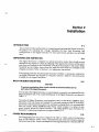
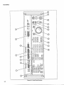
1
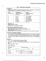
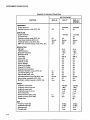
Thank you very much for your shopping on us, if you need any
other manual, email me at [email protected] , I will do
my best to help you.
Please visit our website at www.micromanuals.com for more
manuals.
If you find any others selling the manual made by me, please
email me also.
Attention Please:
The listing of this manual is to help those who need this
manual to repair and maintain their equipment.
If you want to buy this manual, you must agree that this
manual is only charged for Labeling, Service (List Price),
Shipping and Handling Fee;
Thanks and enjoy reading.
MicroManuals or Micromanuals.COM on Ebay
608OA/82A
SYNTHESlzED
RF SIGNAL GENERATOR
Operator Manual
,+-+-
PN 861034
May1990
Rev.1
0 1990 John
11190
Fluke Mfg. Co., Inc. all rights
reserved.
Litho in U.S.A.
FLUKEa
COPYRIGHT AND DISCLAIMER NOTICE
Copyright - Agilent Technologies, Inc. Reproduced with the permission of Agilent
Technologies Inc. Agilent Technologies, Inc. makes no warranty of any kind with regard
to this material including, but not limited to, the implied warranties of merchantability
and fitness for a particular purpose. Agilent Technologies, Inc. is not liable for errors
contained herein or for incidental or consequential damages in connection with the
furnishing, performance, or use of this material or data.
WARRANTY
Notwithstanding
The JOHN
workmanship
the original
warranted
conditions
any
provision
of any agreement
the following
warranty
is exclusive:
FLUKE
MFG. CO., INC., warrants
each instrument
it manufactures
to be free from defects
in material
and
under normal use and service
for the period of 1 -year from date of purchase.
This warranty
extends
only to
purchaser.
This warranty
shall not apply to fuses, disposable
batteries
(rechargeable
type batteries
are
for go-days),
or any product
or parts which
have been subject
to misuse,
neglect,
accident,
or abnormal
of operations.
In the event of failure of a product
covered
by this warranty,
John
returned
to an authorized
Service
Facility
within 1 year of the
discloses
to its satisfaction
that the product
was defective.
The
repair. With regard
to any instrument
returned
within 1 year of
made without
charge.
If the failure has been caused
by misuse,
repairs
will be billed at a nominal
cost. In such case, an estimate
Fluke Mfg. Co., Inc., will repair and calibratean
instrument
original
purchase;
provided
the warrantor’s
examination
warrantor
may, at its option, replace
the product
in lieu of
the original
purchase,
said repairs
or replacement
will be
neglect,
accident,
or abnormal
conditions
of operations,
will be submitted
before work is started,
if requested.
THE FOREGOING
WARRANTY
IS IN LIEU OF ALL OTHER
INCLUDING
BUT NOT LIMITED
TO ANY IMPLIED
WARRANTY
ADEQUACY
FOR ANY PARTICULAR
PURPOSE
OR USE. JOHN
LIABLE
FOR ANY SPECIAL,
INCIDENTAL,
OR CONSEQUENTIAL
TORT, OR OTHERWISE.
If any failure
occurs,
the following
steps
should
WARRANTIES,
EXPRESS
OR IMPLIED,
OF MERCHANTABILITY,
FITNESS,
OR
FLUKE MFG. CO., INC., SHALL
NOT BE
DAMAGES,
WHETHER
IN CONTRACT,
be taken:
1. Notify the JOHN FLUKE MFG. CO., INC., or nearest
the model
number,
type number,
and serial number.
instructions
will be forwarded
to you.
Service
facility, giving lull details
On receipt
of this information,
2. On receipt
of the shipping
instructions,
forward
the instrument,
transportation
the Service
Facility
and the instrument
returned,
transportation
prepaid.
SHIPPING
TO MANUFACTURER
FOR
REPAIR
of thedifficulty,
service
data,
prepaid.
Repairs
and include
or shipping
will be made
at
OR ADJUSTMENT
All shipments
of JOHN FLUKE
MFG. CO., INC., instruments
should
be made via United Parcel Service
or “Best Way”*
prepaid.
The instrument
should
be shipped
in the original
packing
carton;
or if it is not available,
useanysuitable
container
that is rigid and of adequate
size. If a substitute
container
is used, the instrument
should
be wrapped
in paper and
surrounded
with at least four inches
of excelsior
or similar shock-absorbing
material.
CLAIM
FOR
DAMAGE
IN SHIPMENT
TO ORIGINAL
PURCHASER
The instrument
should
be thoroughly
inspected
immediately
upon original
delivery
to purchaser.
All material
in the
container
should
be checked
against
the enclosed
packing
list. The manufacturer
will not be responsible
for shortages
against
the packing
sheet unless notified immediately.
If the instrument
is damaged
in any way, a claim should be filed with
the carrier
immediately.
(To obtain a quotation
to repair shipment
damage,
contact
the nearest
Fluke Technical
Center.)
Final claim and negotiations
with the carrier
must be completed
by the customer.
The JOHN FLUKE MFG. CO., INC, will be happy
this instrument.
Please address
your requests
EVERETT,
WASHINGTON
98206, ATTN: Sales
CG, Eindhoven,
The Netherlands.
*For
European
customers,
Air Freight
to answer
all applications
or usequestions,
which will enhance
your use of
or correspondence
to: JOHN FLUKE
MFG. CO., INC., P.O. BOX C9090,
Dept. For European
Customers:
Fluke (Holland)
B.V., P.O. Box 2269,560O
prepaid.
John Fluke Mfg. Co., Inc., P.O. Box C9090, Everett, Washington
Rev.
7188
98206
Declaration
of the Manufacturer
or Importer
We hereby certify that Fluke Models 6080A and 6082A are in compliance with Postal Regulation
Vfg. 1046 and are RFI suppressed.
The marketing and sale of the equipment was reported to the
German Postal Service. The right to retest this equipment to verify compliance with the regulation
was given to the German Postal Service.
Bescheinigung
des HerstellersAmporteurs
Hiermit wird bescheinigt,
dap Fluke Models 6080A und 6082A in ‘U’bereinstimmung
mit den
Bestimmungen
der Amtsblattverftigung
Vfg. 1046 funk-entsort
sind. Der Deutschen
Bundespost
wurde das lnverkehrbringen
dieser Gerate angezeigt und die Berechtigung
zur ‘U’berprufung
der Serie auf Einhaltung der Bestimmungen
eingeraumt.
John Fluke Mfg. Co., Inc.
INTERFERENCE
INFORMATION
This equipment
generates
and uses radio frequency
energy
and if not installed
and used in strict accordance
with the
manufacturer’s
instructions,
may cause interference
to radio and television
reception.
It has been type tested and found to
comply
with the limits for a Class B computing
device
in accordance
with the specifications
in Subpart
J of Part 15 of FCC
Rules, which are designed
to provide
reasonable
protection
against such interference
in a residential
installation.
However,
there is no guarantee
that interference
will not occur in a particular
installation.
If this equipment
does cause interference
to
radio or television
reception,
which can be determined
by turning theequipment
off and on, the user is encouraged
totry to
correct
the interference
by one or more of the following
measures:
a
Reorient
the receiving
0
Relocate
the equipment
l
Move
l
Plug the equipment
the equipment
antenna
with
away
respect
from
into a different
to the receiver
the receiver
outlet
so that the computer
and
receiver
are on different
If necessary,
the user should
consult
the dealer or an experienced
radio/television
technician
The user may find the following
booklet
prepared
by the Federal Communications
Commission
Resolve
Radio-TV
Interference
Problems.
This booklet
is available
from the U.S. Government
DC 20402. Stock No. 004-000-00345-4.
branch
circuits
for additional
suggestions.
helpful: How to Identify and
Printing Office, Washington,
OPERATOR SAFETY SUMMARY
SAFETY TERMS IN THIS MANUAL
This instrument has beendesignedand testedin accordancewith IEC Publication 348,
Safety Requirements for Electronic Measuring Apparatus. This Operator Manual
contains information, warnings, and cautions that must be followed to ensure safe
operation and to maintain the signal generator in a safe condition.
WARNING statements identify conditions or practices that could result in
personal injury or loss of life.
CAUTION statements identify conditions or practices that could result in damage
to equipment.
POWER SOURCE
The signal generator is intended to operate from a power source that will not apply
more than 264V ac rms between the supply conductors or between either supply
conductor and ground. A protective ground connection by way of the grounding
conductor in the power cord is essentialfor safe operation.
USE THE PROPER FUSE
To avoid fire hazard, useonly a fuse identical in type, voltage rating, and current rating
as specified on the rear panel fuse rating label.
GROUNDING THE SIGNAL GENERATOR
The signal generator is a Safety Class I (grounded enclosure)instrument as defined in
IEC 348. The enclosure is grounded through the grounding conductor of the power
cord. To avoid electrical shock, plug the power cord into a properly wired earth
grounded receptacle before connecting anything to any of the signal generator
terminals. A protective ground connection by way of the grounding conductor in the
power cord is essentialfor safe operation.
USE THE PROPER POWER CORD
Use only the power cord and connector appropriate for the voltage and plug
configuration in your country.
Use only a power cord that is in good condition.
Refer cord and connector changesto qualified service personnel.
DO NOT OPERATE IN EXPLOSIVE ATMOSPHERES
To avoid explosion, do not operate the signal generator in an atmosphere of explosive
gas.
DO NOT REMOVE COVER
To avoid electric shock, do not remove the signal generator cover. Do not operate the
signal generator without the cover properly installed. Normal calibration
is accomplished with the cover closed, and there are no user-serviceable parts inside the signal
generator, so there is no need for the operator to ever remove the cover. Access
procedures and the warnings for such procedures are contained in the Service Manual.
Service procedures are for qualified service personnel only.
DO NOT ATTEMPT TO OPERATE IF PROTECTION
MAY BE IMPAIRED
If the signal generator appears damaged or operates abnormally,
protection may be
impaired. Do not attempt to operate it. When in doubt, have the instrument serviced.
Table of Contents
SECTION
1
TITLE
INTRODUCTION
l-l.
l-2.
l-3.
1-4.
1-5.
l-6.
l-7.
l-8.
l-9.
l-10.
2
3
4
4-3.
2-l
2-l
2-l
2-l
2-2
2-4
2-4
2-5
2-5
. . . . . . . . . . . . . . . . . . . . . . . . . . . . . . . . . . . . . . . . . . . . . . . . . . . . . . . . . . . . . . . . . 3-1
INTRODUCTION
...................................................
FRONT PANEL FEATURES ........................................
REAR PANEL FEATURES
.........................................
FRONT PANEL OPERATION
4-l.
4-2.
l-l
l-2
l-2
1-2
l-2
l-2
l-3
1-3
1-3
l-4
. . . . . . . . . . . . . . . . . . . . . . . . . . . . . . . . . . . . . . . . . . . . . . . . . . . . . . . . . . . . . 2-1
INTRODUCTION
...................................................
UNPACKING
AND INSPECTION
..................................
RACK OR BENCH MOUNTING
....................................
POWER REQUIREMENTS
.........................................
LINE VOLTAGE SELECTION AND FUSE REPLACEMENT
........
CONNECTING
TO LINE POWER ..................................
INTERNAL/
EXTERNAL FREQUENCY REFERENCE
.............
LOCAL AND REMOTE OPERATION
..............................
POWER-ON SEQUENCE
...........................................
FEATURES
3-l.
3-2.
3-5.
. . . . . . . . . . . . . . . . . . . . . . . . . . . . . . . . . . . l-l
INTRODUCTION
...................................................
INSTRUCTION
MANUALS
.........................................
6080A/82A Operator Manual ......................................
6080A/82A Operator Reference Guide ..............................
6080A/82A Remote Programming Reference Guide .................
6080A/82A Special Functions Decal ................................
6080A and 6082A Service Manuals .................................
OPTIONS ...........................................................
WARRANTY
AND SERVICE INFORMATION
.....................
SPECIFICATIONS
..................................................
INSTALLATION
2-l.
2-2.
2-3.
2-4.
2-5.
2-6.
2-7.
2-8.
2-9.
AND SPECIFICATIONS
PAGE
3-l
3-l
3-l
. . . . . . . . . . . . . . . . . . . . . . . . . . . . . . . . . . . . . . . . . . . . . . . 4-1
INTRODUCTION
...................................................
RECALLING
PREVIOUS INSTRUMENT
SETTINGS
AT POWER-UP
.....................................................
ENTERING AND MODIFYING
PARAMETERS
....................
i
4-l
4-1
4-l
(continued on page ii)
TABLE OF CONTENTS,
continued
4-4.
4-5.
4-6.
4A
4A-I
4A-1
4A-2
4A-2
4A-3
4A-3
4A-4
4A-4
, . . . . . . . . . . . . . . . . . . . . . . . . . . . . . . . . . . . . . . . . . . . . . . . . . 48-l
..................................................
INTRODUCTION
.............................
SETTING RF OUTPUT AMPLITUDE
CONVERTING
RF OUTPUT AMPLITUDE
UNITS ................
SELECTING ALTERNATE dB REFERENCE UNITS ...............
USING UNTERMINATED
OUTPUT (EMF) MODE ................
SETTING RF OUTPUT AMPLITUDE
STEP SIZE .................
USING RF AMPLITUDE
RELATIVE MODE ......................
......................
ENABLING AND DISABLING
RF OUTPUT
RF OUTPUT AMPLITUDE
BANDS ................................
USING RF OUTPUT AMPLITUDE
FIXED-RANGE
MODE .......
USING ALTERNATE OUTPUT COMPENSATION
MODES ........
SELECTING ALTERNATE OUTPUT COMPENSATION
DATA ....
MODULATION
4c-1.
4C-2.
4c-3.
4c-4.
4c-5.
4C-6.
4c-7.
4C-8.
4c-9.
4c-10.
4c-11.
4C-12.
4c-13.
4c-14.
4c-15.
4C-16.
4c-17.
4C-18.
4c-19.
4C-20.
4C-21.
. . . . . . . . . . . . . . , . . . . . . . . . . . . . . . . . . . . . . . . . . . . . . . . . . 4A-1
..................................................
INTRODUCTION
.............................
SETTING RF OUTPUT FREQUENCY
SETTING RF OUTPUT FREQUENCY STEP SIZE .................
USING RF OUTPUT FREQUENCY RELATIVE MODE ............
................
ADJUSTING
THE PHASE OF THE RF CARRIER
.............
USING AN EXTERNAL
FREQUENCY REFERENCE
...............................
RF OUTPUT FREQUENCY BANDS
....
RF OUTPUT BLANKING
DURING FREQUENCY CHANGES
RF OUTPUT AMPLITUDE
4B-1.
4B-2.
4B-3.
4B-4.
4B-5.
4B-6.
4B-7.
4B-8.
4B-9.
4B-10.
4B-11.
4B-12.
4c
Entering Parameters Directly . . . . . . . . . . . . . . . . . . . . . . . . . . . . . . . . . . . . . . . 4-2
Editing the Bright Digit . . . . . . . . . . . . . . . . . . . . . . . . . . . . . . . . . . . . . . . . . . . . 4-2
Incrementing and Decrementing by Step . . . . . . . . . . . . . . . , . . . . . . . . . . . . 4-3
RF OUTPUT FREQUENCY
4A-1.
4A-2.
4A-3.
4A-4.
4A-5.
4A-6.
4A-7.
4A-8.
48
PAGE
TITLE
SECTION
4B-1
4B-I
4B-2
4B-2
4B-3
4B-4
4B-4
4B-6
4B-6
4B-7
4B-8
4B-8
. . . . . . . . . . . . . . . . . . . . . . . . . . . . . . . . . . . . . . . . . . . . . , . . . . . . . . . . . . . . . . 4C-1
INTRODUCTION
..................................................
INTERNAL
MODULATION
OSCILLATOR
........................
Setting Modulation Frequency and Step Size ......................
Setting Modulation Level and Step Size ...........................
Enabling and Disabling Modulation Output .......................
Selecting the Internal Modulation Waveform .......................
Using the Extended Resolution Mode for Modulation Frequency
AMPLITUDE
MODULATION
(AM) ...............................
Setting AM Depth and AM Depth Step Size .......................
Activating Internal AM ...........................................
Activating External AM (AC Coupled) ............................
Activating External AM (DC Coupled) ............................
FREQUENCY AND PHASE MODULATION
(FM/+M)
............
Setting FM/4M
Deviation and FM/4M
Step Size .................
Converting FM/+M
Units ........................................
......................................
Activating Internal FM/4M
Activating External FM/+M (AC Coupled) ........................
Activating External FM (DC Coupled) ............................
FMBands
.......................................................
Using Low Distortion and Fixed-Range FM Modes ................
Using Low Rate FM Mode .......................................
ii
...
4C-1
4C-1
4C-2
4c-3
4c-4
4C-4
4C-5
4C-5
4C-5
4C-6
4C-6
4C-7
4C-7
4C-7
4C-9
4C-10
4C-10
4C-10
4C-11
4C-12
4c-13
(continued on page iiij
-.
TABLE OF CONTENTS,
TITLE
PAGE
Using High Rate +M Mode .......................................
............................................
PULSE MODULATION
.............................
Activating External Pulse Modulation
..............................
Activating Internal Pulse Modulation
Using the Mod Oscillator as a Pulse Generator .....................
Setting Pulse Width ..............................................
4C-13
4C-14
4C-14
4C-14
4C-14
4c-15
SECTION
4C-22.
4G23.
4C-24.
4C-25.
4C-26.
4C-27.
4D
INSTRUMENT
4D-1.
4D-2.
4D-3.
4D-4.
4D-5.
4D-6.
4D-7.
4D-8.
4D-9.
4D-10.
4D-11.
4E
4F
STATE MEMORY
. . . . . . . . . . . . . . . . . , . . . . . . . . . . . . . . . . . . . . . . . . . . 4D-1
...........
ORGANIZATION
OF INSTRUMENT
STATE MEMORY
STORING AND RECALLING
INSTRUMENT
STATES ............
RECALLING
A SEQUENCE OF INSTRUMENT
STATES ..........
DIVIDING
MEMORY INTO PARTITIONS
........................
WRITE-PROTECTING
MEMORY LOCATIONS
...................
RESETTING ALL MEMORY LOCATIONS TO
FACTORY DEFAULT
.............................................
STORING AND RECALLING
SINGLE PARAMETERS
...........
SECURE MODE AND NONVOLATILE
MEMORY ERASURE
....
Enabling Secure Mode ............................................
Erasing Nonvolatile Memory ......................................
Changing the erase Operation Repeat Count .......................
4D-1
4D-3
4D-4
4D-4
4D-6
4D-6
4D-6
4D-7
4D-7
4D-7
4D-9
SWEEP .....................................................................
4E-1
4E-1.
4E-2.
4E-3.
4E-4.
4E-5.
4E-6.
4E-7.
4E-8.
4E-9.
4E-10.
4E-11.
4E-12.
4E-13.
4E-14.
4E-15.
4E-1
4E-2
4E-2
4E-3
4E-3
4E-4
4E-5
4E-5
4E-6
4E-6
4E-8
4E-8
4E-9
4E-10
4E-10
INTRODUCTION
..................................................
SELECTING FREQUENCY OR AMPLITUDE
SWEEP ............
SUMMARY
OF SWEEP MODES ..................................
SELECTING SYMMETRIC
OR ASYMMETRIC
SWEEP ..........
SETTING SWEEP DWELL TIME ..................................
FREQUENCY SWEEP .............................................
Setting Frequency Sweep Width ...................................
Setting Frequency Sweep Increment ...............................
Digital Frequency Sweep Example ................................
AMPLITUDE
SWEEP .............................................
Setting Amplitude Sweep Width ...................................
Setting Amplitude Sweep Increment ...............................
Digital Amplitude Sweep Example ................................
CALIBRATING
A RECORDER OR OSCILLOSCOPE
.............
ANALOG FREQUENCY SWEEP ..................................
SPECIAL FUNCTIONS
4F-1.
4F-2.
4F-3.
4F-4.
4F-5.
4F-6.
4F-7.
4F-8.
4F-9.
continued
. . . . . . . . . . . . . . . . . . . . . . . . . . . . . . . . . . . . . . . . . . . . . . . . . . . . . 4F-1
INTRODUCTION
..................................................
ENABLING SPECIAL FUNCTIONS
...............................
VIEWING ENABLED SPECIAL FUNCTIONS
.....................
THE SPCL ANNUNCIATOR
.......................................
MISCELLANEOUS
SPECIAL FUNCTIONS
.......................
Disable Special Functions .........................................
Restore Instrument Preset State ...................................
Execute Self-Test and Display Self-Test Results ....................
Display Loaded Options ..........................................
..
111
4F-1
4F-3
4F-3
4F-4
4F-4
4F-4
4F-4
4F-4
4F-4
(continued on page iv)
TABLE OF CONTENTS,
continued
TITLE
SECTION
4F-10.
4F-11.
4F-12.
4F-13.
46
5
. . . . . . . . . . . . . . . . . . . . . . . . . . . . . . . . . . . . . . . . . 4G-1
4G-1
4G-1
4G-2
. . . . . . . . . . . . . . . . . . . . . . . . . . . . . . . . . . . . . . . . . . . . . . . . . . . . . . 5-l
5-l
5-l
5-2
5-2
5-3
INTRODUCTION
...................................................
..........................
SETTING UP THE IEEE-488 INTERFACE
Address Setup Procedure ..........................................
Talker/ Listener Mode Selection Procedure ..........................
Compatibility Language Selection Procedure ........................
REMOTE PROGRAMMING
5A-1.
5A-2.
5A-3.
5A-4.
5A-5.
5A-6.
5A-7.
5A-8.
5A-9.
5A-10.
5A-11.
5A-12.
5A-13.
5A-14.
5A-15.
5A-16.
5A-17.
5A-18.
5A-19.
5A-20.
5A-21.
5A-22.
5A-23.
5A-24.
5A-25.
5A-26.
5A-27.
5A-28.
5A-29.
4F-4
4F-5
4F-5
4F-5
........................................
GENERAL DESCRIPTION
THE STATUS KEY .................................................
DISPLAYING
SELF-TEST STATUS AND
CALIBRATION/
COMPENSATION
DATA .........................
REMOTE OPERATION
5-l.
5-2.
5-3.
5-4.
5-5.
SA
Display Instrument ID and Software Revision Level ...............
Blank Front Panel Display ........................................
Select Repeat Rate for Step Keys ..................................
Configure Edit Knob and Step Keys ...............................
ERROR AND STATUS REPORTING
4G-1.
4G-2.
4G-3.
PAGE
. . . . . . . . . . . . . . . . . . . . . . . . . . . . . . . . . . . . . . . . . . . . . . . . . 5A-1
INTRODUCTION
..................................................
............................
COMMAND
SYNTAX INFORMATION
..........................................
Parameter Syntax Rules
Extra Space Characters ...........................................
Terminators ......................................................
Incoming Character Processing ....................................
Response Message Syntax ........................................
.....................................
INPUT BUFFER OPERATION
......................................................
COMMANDS
MultipleCommands
..............................................
Command Processing .............................................
Command Restrictions ............................................
Commands That Require the CAL1 CAMP Switch To Be Set .......
.........................
REMOTE/LOCAL
STATE TRANSITIONS
CHECKING THE INSTRUMENT
STATUS .........................
Serial Poll Status Byte (STB) ......................................
BIT ASSIGNMENTS
FOR THE STB AND SRE ...............
SERVICE REQUEST LINE (SRQ) ............................
SERVICE REQUEST ENABLE REGISTER (SRE) ............
PROGRAMMING
THE STB AND SRE .......................
Event Status Register (ESR) ......................................
BIT ASSIGNMENTS
FOR THE ESR AND ESE ...............
EVENT STATUS ENABLE REGISTER (ESE) .................
PROGRAMMING
THE ESR AND ESE .......................
Output Queue ....................................................
Error Queue ......................................................
Instrument Status Register (ISR) .................................
BIT ASSIGNMENTS
FOR THE ISR, ISCR, AND ISCE .......
INSTRUMENT
STATUS CHANGE REGISTER (ISCR) .......
iv
5A-1
5A-2
5A-2
5A-3
5A-3
5A-4
5A-4
5A-4
5A-4
5A-5
5A-5
5A-5
5A-5
5A-6
5A-7
SA-7
5A-7
5A-9
5A-9
5A-10
5A-10
5A-10
5A-12
5A-12
5A-13
5A-13
5A-14
5A-14
5A-14
(continued on page v)
TABLE OF CONTENTS,
SECTION
TITLE
continued
PAGE
5 A-30.
5B
INSTRUMENT
STATUS CHANGE ENABLE
REGISTER (ISCE) ............................................
5A-31.
PROGRAMMING
THE ISR, ISCR, AND ISCE ...............
5A-32.
StatusQueue ..................................
...................
5A-33. IEEE-488 INTERFACE
CONFIGURATION
........................
5A-34. BUS COMMUNICATION
OVERVIEW .............................
5A-35.
Definition: Queries and Commands ................................
5A-36.
Functional Elements of Commands ................................
5A-37.
InterfaceMessages
................................................
5A-38. THE IEEE-488 CONNECTOR
......................................
5A-39. REMOTE PROGRAM EXAMPLES
................................
5A-40.
Using the *OPC?, *OPC, and *WA1 Commands ...................
5A-41.
Using the *DDT and *TRG Commands ...........................
5A-15
5A-15
5A-16
5A-16
5A-16
5A- I7
5A-17
5A-19
5A-21
5A-22
5A-22
5A-23
REMOTE COMMAND
.............................................
5B-1
SUMMARY
...............................
...........................................
5B-1
5B-1
5B-1.
SB-2.
5c
COMMAND
COMMANDS
TALK-ONLY/LISTEN-ONLY
5c-1.
5C-2.
SC-3.
5c-4.
5D
REMOTE
REMOTE
TABLES
...................................
INTRODUCTION
..................................................
TALK-ONLY OPERATION
.........................................
LISTEN-ONLY
OPERATION .......................................
LISTEN-ONLY/TALK-ONLY
EXAMPLE
..........................
COMPATIBILITY
5D-1.
5D-2.
SD-3.
5D-4.
5D-5.
5D-6.
5D-7.
5D-8.
5D-9.
5D-10.
5D-11.
5D-12.
5D-13.
5D-14.
5D-15.
5D-16.
5D-17.
5D-18.
5D-19.
5D-20.
5D-21.
5D-22.
OPERATION
LANGUAGES
.............................................
INTRODUCTION
..................................................
SELECTING THE ACTIVE LANGUAGE
..........................
USING THE 6060 AND 6070 FAMILY LANGUAGES
..............
incompatibilities
..................................................
Converting 6060 and 6070 Programs to Use the 6080 Language .....
USING THE HP 8642 FAMILY LANGUAGE
.......................
IEEE-488 (GPIB) Address ........................................
IEEE-488 (GPIB) Interface Capabilities ............................
Data Input and Numeric Formatting
..............................
DataOutput
.....................................................
HP8642Commands
..............................................
RF Output Frequency ............................................
Relative RF Frequency ...........................................
RF Frequency Sweep .............................................
RF Output Amplitude
............................................
EMFUnits
.......................................................
Relative Amplitude ...............................................
AmplitudeSweep
.................................................
AM/Pulse Modulation
...........................................
FM/4M
.........................................................
Internal Modulation Oscillator ....................................
Instrument Preset/ Partial Preset ..................................
V
5C-1
5C-1
5C-1
5C-2
5C-2
5D-1
5D-1
5D-1
5D-2
5D-2
5D-9
5D-I2
5D-12
5D-12
5D-13
5D-13
5D-13
5D-I 3
5D-16
5D-16
5D-17
5D-17
5D-17
5D-17
5D-17
5D-I7
5D- 18
5D-I9
(continued on page vi)
TABLE OF CONTENTS,
continued
TITLE
SECTION
5D-23.
5D-24.
5D-25.
533-26.
5D-27.
Knob Control/Entry
Off ..........................................
...............................................
Step,IncrementSet
Save/ Recall Register .............................................
Special Functions .................................................
Messages .........................................................
Appendix A
Instrument Preset State . . . . . . . . . . . . . . . . . . . . . . . . . . . . . . . . . . . . . . . . . . . . . . . . . . . . .
Appendix B
Special Function Table . . . . . . . . . . . . . . . . . . . . . . . . . . . . . . . . . . . . . . . . . . . . . . . . . . . . .
Appendix C
Rejected Entry Codes . . . . . . . . . . . . . . . . . . . . . . . . . . . . . . . . . . . . . . . . . . . . . . . . . . . . . .
Appendix D
OverrangeIUncal
Status Codes . . . . . . . . . . . . . . . . . . . . . . . . . . . . . . . . . . . . . . ...*..
Appendix E
Self-Test Status Codes . . . . . . . . . . . . . . . . . . . . . . . . . . . . . . . . . . . . . . . . . . . . . . . . . . . . .
Appendix F
Rear Panel AUX Connector Pinout . . . . . . . . . . . . . . . . . . . . . . . . . . . . . . . . . . . . . . . . .
Appendix G
Fluke Sales and Service Centers . . . . . . . . . . . . . . . . . . . . . . . . . . . . . . . . . . . . . . . . . . .
PAGE
5D-19
5D-19
5D-19
5D-20
5D-20
A-l
B-l
C-l
D-l
E-l
F-l
G-l
List of Tables
TABLE
l-l.
1-2.
2-1.
2-2.
2-3.
3-1.
3-2.
4-1.
4A-1.
4B-1.
4B-2.
4c-1.
4C-2.
4c-3.
4D-1.
4D-2.
4F-1.
4F-2.
4G-1.
5A-1.
5A-2.
5A-3.
5A-4.
5A-5.
5B-1.
5B-2.
5B-3.
SD-l.
5D-2.
5D-3.
5D-3A.
5D-4.
5D-5.
5D-6.
5D-7.
5D-8.
5D-9.
5D-10.
5D-11.
5D-12.
TITLE
Specifications for Model 6080A .............................................
Specifications for Model 6082A .............................................
Standard Equipment
.......................................................
Line Power Cord Types Available from Fluke ................................
Accessories ................................................................
Front Panel Features .......................................................
Rear PanelFeatures ........................................................
Step Size Defaults ..........................................................
Signal Generator Frequency Bands .........................................
Relative Amplitude Unit Combinations
.....................................
RF Output Amplitude Bands ...............................................
FM/ cpM Deviation Limits (FM /4M Enabled) ...............................
FM Band Limits ...........................................................
FM Band Limits - Low Distortion Mode ....................................
Non-Storable/ Recallable Parameters .......................................
Nonvolatile Memory Locations .............................................
Special Function Codes ....................................................
Functions of Edit Knob and Step Keys ......................................
Interpreting Status Codes ..................................................
Remote/ Local State Transitions ............................................
IEEE-488 Interface Function Subsets Supported .............................
Functional Elements of Commands .........................................
Interface Messages that the Signal Generator Accepts ........................
Interface Messages that the Signal Generator Sends ..........................
Remote Command Summary ...............................................
Units That Can Be Used With Remote Commands
..........................
Remote Commands ........................................................
6060 Compatibility Language Codes and Special Functions ..................
6070 Compatibility Language Codes and Special Functions ..................
6060 and 6070 Compatibility Language Commands ..........................
Commands not in 6060 or 6070 Compatibility Language .............
6060 and 6070 Compatibility Language Units ........................
IEEE-488 Interface Capibilities/ HP8642 Language ..................
6080 to HP8642 Error Code Mapping ...............................
HP8642 Commands That Are Not Emulated ........................
HP8642 RF Output Frequency Commands That Are Not Emulated . .
Frequency Sweep Commands That Are Not Emulated ...............
Amplitude Sweep Commands That Are Not Emulated ...............
FM/4M
Commands That Are Not Emulated .......................
HP8642 Special Functions Emulated ................................
viilviii
PAGE
.......
.......
.......
.......
.......
.......
.......
.......
.......
.......
l-5
1-12
2-2
2-2
2-3
3-3
3-12
4-3
4A-4
4B-5
4B-6
4C-9
4C-11
4C-12
4D-2
4D-2
4F-2
4F-5
4G-2
5A-7
5A-9
5A-18
5A-19
5A-21
5B-2
5B-7
5B-8
5D-3
5D-5
5D-7
5D-10
5D-11
5D-11
5D-14
5D-15
5D-15
5D-16
5D-18
5D-18
5D-20
List of Illustrations
FIGURES
2-1.
2-2.
3-1.
3-2.
5A-1.
5A-2.
5A-3.
5A-4.
5A-5.
TITLE
Line Power Cords Avaliable from Fluke .....................................
Fuse/ Line Voltage Selection Assembly .......................................
Front Panel Features ........................................................
Rear Panel Features ........................................................
Overview of Status Data Structure ..........................................
Bit Assignments for the STB and SRE ......................................
Bit Assignments for ESR and ESE ..........................................
Bit Assignments for the ISR, ISCR, and ISCE ..............................
IEEE-488 Connector and Pin Assignments ..................................
ix
PAGE
2-3
2-4
3-2
3-11
5A-8
5A-9
5A-11
5A-14
5A-21
6080A182A
Synthesized
RF Signal
X
Generator
Section 1
Introduction
and Specifications
l-l.
INTRODUCTION
The 6080A and 6082A Synthesized RF Signal Generators are fully programmable,
precision, synthesized signal sources.They are designedfor applications that require
good modulation, frequency and output level performance with excellent spectral
purity. Both Signal Generators are well suited for testing a wide variety of RF
components, sub-assemblies,and systems, including filters, amplifiers, mixers, and
receivers,particularly off-channel radio testing.
Both models are called the Signal Generator in this manual. It is noted wherever
information applies specifically to one model or the other.
Specifications of the Signal Generator areprovided at the end of this section. Features
of the Signal Generator include the following:
0
Frequency range, in 1 Hz steps, as follows:
6080A: 10 kHz to 1056MHz
608214: 100 kHz to 2112 MHz
0
Amplitude ranges as follows, with 0.1 dB resolution:
6080A: +19 to -140 dBm for RF output frequencies below 512 MHz, and
+17 to -140 dBm for RF output frequencies 512 MHz and above
6082A: +16 to -140 dBm for RF output frequencies below 1056 MHz, and
+13 to -140 dBm for RF output frequencies 1056 MHz and above
0
Amplitude units acceptedand displayed: dB, dBm, dBf, dBpV, dBmV, pV, mV, V,
\ .
and EMF
l
Internal and external modulation: AM, FM, 4M, and pulse
l
Internal 0.1 Hz to 200 kHz direct-digital synthesis modulation oscillator that
provides sine, square, triangular, and pulse waveforms
0
Digital frequency sweep and digital amplitude sweep
0
Fifty storable and recallable instrument state memory locations
l-l