1
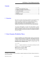
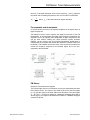
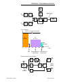
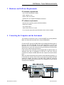
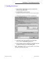
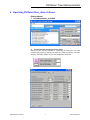
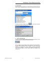
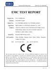
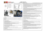
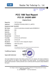
®
®
®
Products: R&S UPL, R&S UPV, R&S SML
FM Stereo Tuner Measurements
with Audio Analyzers R&S® UPV or R&S® UPL and
Signal Generator R&S® SML with R&S® SML-B5 option
Application Note RAC-0502-0012
This Application Note presents a program called FMTunerMeas, which combines FM tuner measurements
to form automatically running sequences in line with DIN EN60315-4. It is an extension of Application Note
1GA43 and can be used with the Audio Analyzer R&S UPV.
Subject to change – Mike Cheong, Tilman Betz 03.2006 – RAC-0502-0012 version 1.1
FM Stereo Tuner Measurements
Contents
1
2
3
4
5
6
7
8
9
1
Overview ................................................................................................. 2
Stereo Frequency Modulation Theory ..................................................... 2
Hardware and Software Requirements ................................................... 5
Connecting the Computer and the Instrument ........................................ 5
Installing the Software ............................................................................. 6
Operating FMTunerMeas_demo Software.............................................. 7
Literature ................................................................................................. 9
Additional Information ............................................................................. 9
Ordering Information ............................................................................... 9
1 Overview
More and more modern mobile phones and PDAs come integrated with FM
chipsets. To analyze the quality of RF FM tuners, a large number of
measurements have to be performed. This Application Note presents a
program, FMTunerMeas, which combines automatic FM tuner
measurement sequences in line with DIN EN60315-4. It is an extension of
Application Note 1GA43 and can be used with the Audio Analyzer R&S UPV.
The program FMTunerMeas is included. Run FMTunerMeas to perform
measurements via GPIB remote control or to simulate the test sequences
without any hardware connected. The report with measurement graphics
and the test results are generated automatically in the appropriate folders in
the user’s computer.
2 Stereo Frequency Modulation Theory
In FM, the amplitude of the information signal is used to vary the carrier
frequency, while the frequency of the information signal determines the rate
at which the carrier frequency changes. For a transmitter with linear
modulation characteristics, the frequency deviation of the carrier is directly
proportional to the amplitude of the applied modulating signal. The
frequency deviation is defined as follows:
= k f * EM
where
k f (= frequency deviation/V) is the frequency sensitivity of the FM
modulator and
is the peak frequency deviation.
Mathematical analysis of FM
E fm (t ) = Ec sin( 2 f c t + m f sin 2 f m t )
The R&S logo, Rohde & Schwarz and R&S are registered trademarks of Rohde & Schwarz GmbH & Co.
KG and its subsidiaries.
RAC-0502-0012 version1.1
2
Rohde & Schwarz
FM Stereo Tuner Measurements
where Ec is the peak amplitude of the carrier frequency, fc and fm represent
the carrier and modulating frequencies, and mf is the index of modulation.
mf =
fM
where
f M is the rated maximum system deviation.
Pre-emphasis and de-emphasis
In normal speech and music, the spectral amplitude of the signal drops at
higher frequencies.
This behavior can be used to improve the signal-to-noise ratio of the FM
transmission. In the transmitter the higher signal frequency amplitudes are
amplified. Due to the typically lower amplitudes at higher frequencies, this
can be done without violating the rated maximum system deviation
(RMSD). On the receiver side, this frequency-dependent amplification is
compensated by a lowpass with exactly the same time constant used in the
transmitter. This lowpass reduces the noise in the receiver but produces an
overall flat frequency response for the desired signal, due to the preemphasis in the transmitter.
FM Stereo
FM Stereo Transmitter block diagram
The left and right sources of information are first pre-emphasized and then
fed to adder circuits. The output of one adder is the sum of the two signals
(L + R), and the output of the other adder is the difference of the two signals
(L H R). The L H R signal is applied to a balanced modulator driven with a
38 kHz signal. The output of the balanced modulator is a DSBSC AM signal
centered at 38 kHz.
RAC-0502-0012 version1.1
3
Rohde & Schwarz
FM Stereo Tuner Measurements
Level / Deviation
Spectrum of the Stereo MPX Signal
S=
(L - R ) / 2
M=
(L + R ) / 2
RDS
Spectrum
0
10
20
30
40
50
19
38
Pilot
Stereo Subcarrier
(suppressed)
60
f / kHz
57
RDS Subcarrier
(suppressed)
FM Stereo Receiver block diagram
Filter
19 kHz
38 kHz
Deemphasis
19 kHz
FM
Receiver
Output of
the
demodulator
RAC-0502-0012 version1.1
Bandpass
(23 ... 53 )
kHz
Lowpass
filter
4
Demodulator
S
Left
channel
L
To the AF
Amplifiers
Matrix
R
M
Deemphasis
Right
channel
Rohde & Schwarz
FM Stereo Tuner Measurements
3 Hardware and Software Requirements
PC hardware requirements
CPU: Pentium III 800 MHz or better
RAM: 128 MB or more
Monitor: VGA color monitor
IEC/IEEE bus: NI-compatible IEC/IEEE bus interface
PC software requirements
Microsoft 32-bit operating system (Windows 2000/XP)
GPIB driver installed
CVI runtime engine
VISA runtime version 2.5 or later
For a document report, Microsoft Word 2000 or later must be installed
4 Connecting the Computer and the Instrument
The instrument connection is set up via an IEC/IEEE bus primary address.
Make sure that each instrument has a unique GPIB address.
Connect the RF output of the R&S SML to the unbalanced antenna input of
the tuner. Since the R&S SML has an output impedance of 50 ohm, the
generator has to be matched to the tuner. Usually the coaxial 75 ohm
antenna input is used. We recommend using the Matching Pad R&S RAM,
which can be ordered under 358.5414.02.
If the receiver to be measured is only equipped with a balanced input, an
adequate balun with an impedance of 240 ohm or 300 ohm must be
connected in between the R&S SML's 50 ohm output the receiver balance
input.
Make sure that measurements are performed with adequate grounding, e.g.
to eliminate hum pick-up. Since tuners are normally not grounded and their
outputs are floating, the inputs of the R&S UPV / R&S UPL should be
grounded, provided a ground connection is not established via the antenna
connected to the R&S SML.
FM Stereo Tuner
RAC-0502-0012 version1.1
5
Rohde & Schwarz
FM Stereo Tuner Measurements
5 Installing the Software
1. Extract the ZIP file, FMTunerMeas_demo.zip, available for free
download from the R&S website.
2. Start SETUP.EXE to install the program.
Program files are copied to a directory of your choice during installation.
3. Complete the registration form to receive a registration key.
4.
Enter the key code in the registration form and click “Start”.
The main window for FMTunerMeas_demo appears.
5. Once the program has been registered, the registration form will
not appear the next time you run FMTunerMeas_demo.
NOTE: If FMTunerMeas_demo has not been registered, you can still start
the program by clicking the “Start” button.
RAC-0502-0012 version1.1
6
Rohde & Schwarz
FM Stereo Tuner Measurements
6 Operating FMTunerMeas_demo Software
Getting started:
1. Start FMTunerMeas_demo.EXE
2. Connection and instrument control setup
Before you can use this software for connecting the instrument, you must
configure the program to match your setup (e.g. GPIB connection), and then
click the “Test Setup” button for your test configuration as follows:
RAC-0502-0012 version1.1
7
Rohde & Schwarz
FM Stereo Tuner Measurements
3. Run the test
Before you run the test program, you should select the test procedures you
want or click the “Selected All Items” button to select all the test procedures.
You also can click the “Report” button
that you want to add to your report files.
to include the information
4. Run the simulation test
You can execute this software without connecting any instruments. In order
to do that, you have to enable the Simulation check box.
Note: In order to run this software properly, please close the Tuner.BAS or
any other BASIC program running in the R&S UPL. If MS Word is not
installed in the controller PC, you can enable "Txt Format" and disable
"Word format + Diagram". If you want a Word printout format with picture
results, MS Word 2000 or a later version needs to be installed in the
controller PC.
RAC-0502-0012 version1.1
8
Rohde & Schwarz
FM Stereo Tuner Measurements
7 Literature
Audio Analyzer R&S UPL Operating Manual
Audio Analyzer R&S UPV Operating Manual
Signal Generator R&S SML Operating Manual
1GA43_0E
Tilman Betz, Measurements on RF radio tuners with Audio
Analyzer R&S UPL and Signal Generator R&S SML with option -B5.
1GA24_1E
Klaus Schiffner, Marco Brusati, Measurements on Tuners
using the Audio Analyzer R&S UPL or UPD and Signal Generator R&S
SMT.
1EC 60315-4: 1997
Methods of measurement on radio receivers for
various classes of emission – part 4: Receivers for frequency modulated
sound broadcasting emissions.
TM
NI-VISA User Manual, National Instruments, available for free download:
http://www.ni.com/visa
8 Additional Information
For additional information or further suggestions, please contact your
nearest Rohde & Schwarz office or [email protected].
9 Ordering Information
Audio Analyzer
R&S UPL
R&S UPV
1078.2008.06
1146.2003.02
Signal Generator
R&S SML01
R&S SML02
R&S SML03
R&S SMV03
R&S SML-B5
9 kHz to 1.1 GHz
9 kHz to 2.2 GHz
9 kHz to 3.3 GHz
9 kHz to 3.3 GHz
Stereo/RDS Coder (option)
1090.3000.11
1090.3000.12
1090.3000.13
1147.7509.13
1147.8805.02
Accessory
R&S RAM
Matching Pad 50/75 Ohm
0358.5414.02
ROHDE & SCHWARZ System & Communication Asia Pte Ltd Regional Application Center
1 Kaki Bukit View #04-12, TECHVIEW Singapore 415941
Telephone +65 6513 0475 Fax +65-6846 1090 Internet: http://www.rohde-schwarz.com
This Application Note and the supplied programs may only be used subject to the conditions of use set forth in the
download area of the Rohde & Schwarz website.
RAC-0502-0012 version1.1
9
Rohde & Schwarz