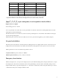
1
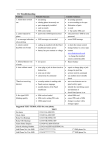
System User Manual
1. Main Function Feature Of The Wireless Intelligent Protection And Security Alarm System
DC 9V power supply, standby current than 25 mA
Six groups of telephone numbers can be pre – stored
10 seconds pre – recorded memo message
Long distance (via public telephone network) set guard status or withdraw guard to the alarm system
Long distance (via public telephone network) monitor the backgrounds sound around the alarm system
Guard setting time delay option (0 – 90 seconds selectable by user)
Alarm setting time delay option (0 – 90 seconds selectable by user)
Siren alarm time length control option (1 – 20 minutes selectable by user)
Telephone line cut off alarm function option
Fourteen wireless zones plus two wired zones, zone 2, 3, 4, 5 can be closed or opened independently
One emergency key for help is provided on the main set
Two emergency key for help is provided on the remote controller which will make the alarm system
Give out loud sound or not as well as dialing when being trigged
Convenient key input is prepared on the front panel
100 dB siren speaker enclosed
Various of door magnetic switch and human body infra – red detector are configurable
Rechargeable DC9V power transformer provided for power cut backup
The alarm system can report the alarm messages to an administration host computer immediately via the public
Telephone network or RS – 485 communication protocol
2. Guard Area Setting
AST 2008G – 16 is sixteen zones alarm panel, its encoding method as follows:
Encoding list:
Zone number
Zone Code
Detectors option
Function
1
2212
Panic button with alarm
Always guarding
voice
2
2211
PIR, door contacts, smoke
The
zone
can
and gas detectors etc
closed independently
3
2121
As above
As above
4
2112
As above
As above
5
2111
As above
As above
6
1222
Panic button without alarm
Always guarding
be
voice
7
1221
PIR, door contacts, smoke
and gas detectors etc
8
1212
As above
9
1211
As above
1
10
112
As above
11
1121
As above
12
1112
As above
13
1111
As above
14
2222
As above
15
Wire Zone
Normally closed
16
Wire Zone
Normally closed
3. Operation Method of the Wireless Intelligent Protection and Security Alarm SY
Zone 2nd, 3rd, 4th, 5th, is part arming zones, it can be opened or closed as follows:
Part arm: password + “partarm”
Full arm: password + “fullarm”
Cancel arming: password + “disarm”
Zone 1st is panic button zone with sound, zone 6th is panic button zone without sound, both zone will trig alarm when received the
alarm signal even under disarming state.
The fifteen and sixteen zone are wired zones, there are short ship connecting the two zone terminals on the backside of the keypad,
disconnect the slip will trig alarm.
When in later grade version, the sixteen zone will be used to remote operate the home appliances power switch by telephone.
Set guard and withdraw
This alarm system can be divided to four alarm guard areas. Each guard area can configured with several door entry detectors, Gas
leakage detectors and smoke detectors. By setting on the main alarm set each guard area can be opened or closed as you needed.
When a guard area be set closed, its alarm messages will not send out.
Set guard on main set: press key: Password + Fullarm
Withdraw guard on main set: press key + Password + Disarm
Emergency alarm function:
When met emergent event, you can press the emergency key, the system will immediately put into emergency alarm state, if you press
the emergency key on the remote controller, the system’s siren speaker will give out loud sounds as well as dial out the pre-stored
telephone number and if you press the emergency key “S” on the remote controller, the system’s siren speaker will not give out loud
sound but dial out the pre-stored telephone number as usual.
2
Alarm process
When alarm broke out, the horn will resound as you selected, the system will automatically dial out the pre-recorded memo messages
receive telephone.
You can press the key on you alarm receive telephone as you need:
Press key “1” : set guard
Press key “2’: withdraw guard
Press key “5”: open siren
Press key “6”: shut off siren
Press key “7”: open background sound monitor
Press key ”8”: close background sound monitor
Press key “9”: withdraw guard and auto-dialer hook on
If you want to extend the monitor time, you can press the digit key “7” again not more than 20 seconds interval
Telecommunication setting by telephone:
If you need to operate the alarm system far away, you can dial the alarm system by any other telephone, after hearing eight times
ring-back sound, the alarm system will automatically hook off, you can set the alarm system by input digital numbers on the telephone
you used, at first, input four digits password code on your called telephone not more than ten seconds, then, input following digital
code as operation command:
“1”: setting guard of the alarm system
“6”: shut off the horn
“2”” withdraw guard of the alarm system
“7”: open background monitor
“3”: setting alarm with sound
“8”: close background monitor
“4”: setting alarm with no sound
“9”: exit setting and hook on
“5”: start up the horn
If you want to extend the monitor time, you can press the digit key “7” again not more than 20 seconds interval. If not input key more
than ten seconds, the alarm system auto-dialer will hook on automatically
Alarm system setting method:
1. Store alarm telephone
Press key: “password + sto” + “group number (1-6)” + ”*” + “telephone number + “sto”
2. Cancel alarm telephone number
press key: “password + sto” + “group number (1-6)” + “*” + “sto”
3. Alarm memo recording
press key: “password + REC” + memo message + “ REC”
you can start record, speaking time not more than 10 seconds, than press the key “password + REC” again, the record LED
indicator went out, this finished the recording process
4. Setting alarm with sound
press key “password + pro” + “1”, the system will give out sound when alarm taking place
5. Setting alarm with no sound
press key “password + pro” + “2”, the system will not give out sound when alarm taking place
3
6. Alarm speaker hooting time option
press key “password + pro” + “3” + “pro” + “time (1-20 min)” + “pro” the speaker hooting time can be set to range between 1 -20
minutes
7. Clear all settings
press key “password + pro” + “4”, this function clear all settings, include pre-stored telephone numbers, all setting will be restored
to its initial setting as it manufactured out
8. Setting guard with delay time option
press key “password + pro” + “5” + “pro” + “time(0-90s)” + “pro” setting guard with delay time can set to range between 0-90
seconds
9. Alarm with delay time option
press key “password + pro” + “6” + “pro” + “time (0-90s)” + “pro” alarm with delay time can be set to range between 0-90
seconds
10. Open telephone line cut-off detect function
press key “password + pro” + “7”
this function will make the alarm system hooting when its telephone line cut off
11. Close telephone line cut-off detect function
press key “password + pro” + “8”
this function will not make the alarm system hooting when its telephone line cut off
12. Modify telecommunication password
press key “password + pro” + “9” + “pro” + “four digit password” + “pro” this four digit password is used in telecommunication
operation the initial settings is “1234”
13. Setting network connection user ID code
press key “password + pro” + “0” + “pro” + “four digit code” + “pro”
this four digit user ID code is used in network connection application
4. Infrared Detector Installation and Use
Open the power switch on the side of the detector at first. Mounting height is adjust to 2.2m or so. Mounted on the corner of the room
is preferable, and its detecting direction perpendicular to the people walking direction will have best effect.
Mounting method: take out the bracket in the accessories and fix it on your wall, fix the detector to the bracket and adjust its detection
angle to best position
The following aspect should be noted:
1.
The infrared detector may not direct to outward window
2. Obstacles on its front have negative effect
3. More than two infrared detectors should not be installed on the same area
4. Strong wind flow, fire, radiator should be avoided, for it may trig wrong alarm message
5. When the infrared detector powered up, it will take five minutes to adapt itself to normal working mode
6. The infrared detector can only used in closed room, not used in open ground
4
5. Door Entry Detector (Magnetic Switch & Emitter) Installation and Use
1. The emitter of door entry detector us mounted on the edge of moveable door, and the magnetic bar is mounted on the fixed
doorframe. The two pieces of devices must be not more then 1cm distance when the door closed
2. The magnetic bar must be installed near to the emitter side of LED indicator
3. When the door opened from the position, the emitter’s supper LED indicator will light up for one second, this means the door entry
detector works well
4. The upper LED indicate sending alarm message to the main auto-dialer, the lower LED indicate the power supply is low battery
6. System Maintenance and Protection
1. Avoid direct sunlight, excessive high or low temperature and moist environment
2. Avoid placed on unstable place
3. Avoid liquid flow into the devices
4. Do not use other power supply for substitution
5. The battery of remote controller, infrared detector and door entry emitter need to be replaced while it is low battery
(the battery usually has several month life time)
Encoding and decoding method of the wireless alarm system
This alarm system use wireless transmission style communicate with its wireless detectors. To protect each alarm system from
interfering each other, the wireless signal can use different encoding style for different alarm system. You can add detectors to an
alarm system by encode the detectors.
Each alarm system has its unique wireless communication code, this include 8 bit address code A0, A1, A2, A3, A4, A5, A6, A7, and 4
bit zone code (or data code) D0, D1, D2, D3, each set of alarm system has only one address code, but can have several zone code. The
address code is for communication only, we printed it out on the bottom side of the alarm set, marked as “Product No”, the zone code
is used to distinguish different alarm signal from different detector (or same kind detectors with different encoding). For example, we
have 16 LED indicator on the keypad of the alarm set, the “alarm 1” LED is corresponding to zone1, the “alarm 2” LED is
corresponding to zone 2, the “alarm 3” LED is corresponding to zone 3, the “alarm 4” LED is corresponding to zone 4
We use the “short jumper slip” option to realize the encoding, you can use a screw driver to take off the screw of the infrared detectors
and open the cover, on the power switch side of the electronic circuit board, you can see 36 metal pins, this 36 metal pins is used to
encode the 8 bit address code and 4 bit zone code
You can also open the emitter part of the door entry contacts, there are also 36 metal pins on the side of the electronic circuit board.
This 36 metal pin is also used to encode the 8 bit address code and 4 bit zone code.
There are total 3 row pins, each row has 12 pins, the 12 pins in the row near the IC SC2262 (or HS2262, or PT2262) is high electric
level, marked by H, the 12 pins in the row near the side of the electric circuit board is low electric level, marked by L, the 12 pins in
the middle row is so be set by short jumper slip, if a pin in the middle row is connected by a short jumper slip to the H row pin, we
5
called the pin encoded as “1”, if a pin in the middle row is connected by a short jumper slip to the L row pin, we called the pin
encoded as “2”, if a pin in the middle row is not connected by a short jumper slip (or in float state), we called the pin encoded as “0”,
the 8 pins in the middle row for address code has three encoding state, “1”, “0”, encoding state, “1”. 2”, that is say the 4 bit zone code
has no float state “0”
Fig.6 illustration diagram of infrared detector encoding
Fig.7 illustration diagram of door entry detector encoding
Fig.8 the 8 bit address code in the middle row is set as “21120102”, the zone code is “2211” (zone 2)
Fig.9 the 8 bit address code in the middle row is set as “11100222” , the zone code is “2121” (zone 3)
Fig.10 the 8 bit address code in the middle row is set as “12202011”, the zone code is “2112” (zone 4)
Fig.11 the 8 bit address code in the middle row is set as “22212011”, the zone code is “2112” (zone 4)
Fig.12 the 8 bit address code in the middle row is set as “11011220”, the zone code is “2111” (zone 5)
If you want to add detector to your alarm, there will be two method, the first method is you configure the detector according to the
short jumper slip setting way same as the detectors in your standard kit, the second method as you consult the 8 bit address code from
the “Product NO” on the bottom of your alarm set, and encode 4 bit zone following the above schematic diagram as you need.
The wireless smoke detector and gas leakage detector each has a wireless emitting module inside the plastic cover. There are also 36
pins to set the 8 bit address code and 4 bit zone code on the emitting module
The 8 bit address code is on the bottom side, and the 4 bit zone code is on the right side, the 8 bit address code is also same as infrared
detector for the same alarm set, but we can set the 4 bit zone code as 24 hours guard zone, of course, your can also set the zone code as
zone, 1, 2, 3, 4, as you like. The 24 hours guard zone will report alarm messages even if you withdraw guard
A wireless emergency button is generally configured as 24 hours guard zone in the same method
6