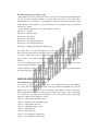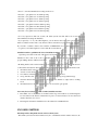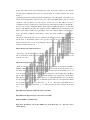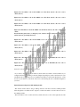
1
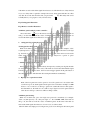
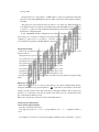
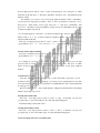
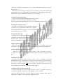
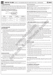
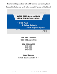
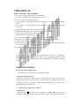
USER MANUAL
:
MAIN FUNCTION AND FEATURES
1. DC 9V power supply, standby current less than 20mA
2. Six groups of alarm telephone numbers can be pre-stored
3. Ten seconds pre-recorded memo messages
4. Long distance via public telephone network set guard status or withdraw guard to the main
dialer
5. Long distance via public telephone network monitor the background sound around the
auto-dialer
6. Setting guard delay time 0~90 seconds for four guard zone
7. Setting alarm delay time 0~90 seconds for four guard zone alarm signal
8. Siren hooting time length control option 1~20 minutes
9. Telephone line cut off alarm function option
10. Six wireless distinguishable guard zones LED indicator on the main set
11. Each of the four guard zones can be set on guard or withdraw guard independently
12. One panic key for help provided on the main set
13. Two panic keys for help is provided on the remote controller which will make the main dialer
give out loud sound or not as well as dialing when being trigged
14. Convenient key input is prepared on the front panel
Various kinds of door magnetic switch and PIR infrared detector are configurable.
Rechargeable DC9V power transformer provided for power cut backup.The dialer can report
the alarm messages to an administration computer immediately via the public telephone
network..
OPERATION METHOD
Fig.1 System connection illustration
Note:the extension can connected to your telephone machine
Set guard and withdraw guard
This alarm system can be divided into four alarm guard zones. Each guard zone can
configured with several door entry detectors, infrared detectors, gas leakage detectors and
smoke detectors. You can set guard or withdraw guard using the remote controller or by
pressing the keypay on the main set.
1. Setting guard by using remote controller
*Setting guard:
Press and release
key on the remote controller, the ‘ GUARD” LED on the main set
will light up ,buzzer beep one time ,the main set went into status of setting guard. At this time,
if the main set received the alarm signals from detectors, it will alarm if set no delay time,but
if you set a delay time for guard,for example 30 seconds, setting guard will take into effect
only after 30 seconds later from the time you pressed the
key. This delay time can be
normally left for you to prepare to exit your house entry.
Fig.2 Setting panel illustration
Fig.3 Remote controller illustration
*withdraw guard setting by remote controller:
Press and release
key on the remote controller, the “GUARD”LED on the main set
will go out ,the main set went into status of withdraw guard. At this time, if the main set
received the alarm signals from all detectors of zone 1,2,3,4, it will not alarm.
2. setting guard by pressing keypad on the main set
*Setting guard on the keypad:
When not in alarm state,press four digits user password consecutively (for example: “1234”,
ect),then press key “set” ,then press digit “ 9”, the “GUARD” LED on the main set will light
up ,the main set went into status of setting guard. At this time if the main set received the
alarm signals from detectors, it will alarm at once or delayed for a period of option
time(0~90s),
* withdraw guard on the keypad
Press four digits user password consecutively, then press key set,then press digit 0, the main
set went into withdraw guard, in this state, if the main set received the alarm intruder signal
from the detectors , it will not alarm , but if it received trigger signal from the panic button of
the remote controller, it will alarm and dial out telephone numbers automatically.
3. Open or close a guard zone alarm
Each of the four guard zone can be opened or closed, if a guard zone is closed, the main
set will not report out alarm signal from the guard zone received.For example ,if a PIR
detector or door contacts is set belong to guard zone 3,when this detector emit signal to
the alarm main set, the main set zone 3 will not report signal out even in guard state,but
other detectors belong to other zones will be working as usual..
*withdraw guard setting:
When not in alarm state, press four digits user password consecutively (for example:
“1234”, ect),then press key “set” ,then press digit “ 0 ”, the “GUARD” LED on the main set
will go out ,the main set went into status of withdraw guard. At this time if the main set
received the alarm signals from detectors of zone 1,2,3,4,, it will not alarm.
When in alarm state,simply press four digits user password on the keypad will cancel guard
and stop alarm.
Each guard area is corresponding to a LED indicator on the front panel,when alarm take
place,the corresponding LED light up, then the alarm system dial out the telephone numbers
and alarm.
The guard zone doesn,t mean the same area ,that is to say, detectors in different places can
be configured into the same guard zone and light up the same alarm LED. As how to configure
a detector to a guard area will be illustrated later.When this alarm unite manufctued out,its
initial status is setting full guard.
In this AST-2008D standard configuration kit( standard configuration),the inclosed door
entry detector( door contacts) is configured to the guard zone 2st, the enclosed infrared detector is
configured to guard zone 1st, according to your need ,you can add any detectors to guard
1,2,3,4,which corresponding to the LED indicator respectively.
Partial guard setting:
Each of the four guard zone can be opened or closed independently by input digit key on the
keypad as follows:
Open guard zone 1: press four digit password first,then press: set+1
Close guard zone 1: press four digit password first,then press: set+2
Open guard zone 2: press four digit password first,then press: set+3
Close guard zone 2: press four digit password first,then press: set+4
Open guard zone 3: press four digit password first,then press: set+5
Close guard zone 3: press four digit password first,then press: set+6
Open guard zone 4: press four digit password first,then press: set+7
Close guard zone 4: press four digit password first,then press: set+8
If a guard zone is set closed,the detectors of the zone will not trig any alarm even in guard setting
status.
Emergency alarm function:
When met emergency event, you can press the panic key, the system will immediately put into
emergency alarm state,if you press the panic key
on the remote controller,the system,s siren
will give out loud sound as well as dial out the pre-stored telephone numbers, and if you press the
panic key “S” on the remote controller, the system,s siren will not give out sound but dial out the
pre-stored telephone numbers as well.
There is also an panic key on the forward side of the alarm main set.
Alarm System setting method:
1.Store alarm telephone number
Press key on the keypad as follows:
“four digit user password” + “store” + “group number(1~6)” + “*” + telephone number +
“store”
For example, if you want to store first group telephone numbers such as “66778899”, you press
key four digit password (such as “1234” or other ) at first,then press “store”, then press“1”, which
means first group ,then press “*”, then press “66778899”, then press“store” , this finish first group
numbers storing.
For example, if you want to store second group telephone numbers such as “012345678”,
you press key four digit password (such as “1234” or other ) at first,then you press key “store”,
then press“2”, which means second group ,then press “*”, then press “012345678”, then
press“store” , this finish second group numbers storing. You can store maximum total six groups
of telephone numbers respectively.
If your alarm telephone connected to an extension telephone line, and have to dial a digital
number such as “9” or “0” ,ect. Before input the telephone number, you can store the alarm
telephone numbers like this ,
Press key: four digit password (such as “1234” or other ) at first,then you press key “store”+
“group number(1~6)” + “*” +“9”(or “0”,ect.) + “*” + telephone number + “store” .
2. Delete alarm telephone number
Press key: four digit password (such as “1234” or other ) at first,then you press key “store”+
“group number(1~6)” + “*” + “store” .
For example, if you want to delete second group telephone numbers ,press key: four digit
password (such as “1234” or other ) at first,then you press key “store”, then press “2”,which
means second group,then press “*” ,then press “store”, this delete second group telephone
numbers.
3.Alarm memo recording
Press key: four digit password (such as “1234” or other ) at first,then you press key “record”
and release, the record LED indicator light up ,you can start record ,speaking time not more than
10 seconds, then press the key “record” again, the record LED indicator went out ,this finished the
recording process.
Record content can be as : “ this is alarm telephone, which place which home has found illegal
intruders, please help to process it”.
4.Setting alarm with sound
Press key : four digit password (such as “1234” or other ) at first,then you press key
“program”+key “1”, the system will give out sound when alarm taking place.
The initial settings is alarm with sound .
5.Setting alarm with no sound
Press key : four digit password (such as “1234” or other ) at first,then you press key
“program”+key “2”, the system will not give out sound when alarm taking place.
6.Clear all setting and restore to its initial values
Press key: four digit password (such as “1234” or other ) at first,then you press key “program”,
then press key “4” . “
This function clear all settings but the user password, include pre-stored telephone numbers, all
settings will be stored to its initial settings as it manufactured out. This fuction is often useful to
diagnosis the “obstacles” which may be resulted by your wrong setting.
7.Alarm siren hooting time setting
Press key: four user digit password at first,then you press key:
“program”+“3”+“program”+ time(1~20minutes)+ “program”
siren hooting time when alarm taking place can be set to 1~20minutes its initial value is 1 minute.
8.Setting guard with delay option
Press key: four user digit password at first,then you press key:
“program”+“5”+“program”+ time(1~90seconds)+ “program”
setting guard with remote controllers or by pressing keypad will be valid after delay this option
time, its initial value is zero, no delay.
9.Setting alarm delay time
Press key: four user digit password at first,then you press key:
“program”+“6”+“program”+ time(1~90seconds)+ “program”
When the main set received alarm signal under guard state,it will waite a period of time
0~90seconds and then report alarm, the initial value is zero, no delay.
10.Open telephone line cut-off detect fuction
Press key: four user digit password (such as “1234” or other ) at first,then you press key
“program”+“7”, this function will make the alarm system hooting when its telephone line cut off.
11.Close telephone line cut-off detect fuction
Press key: four user digit password (such as “1234” or other ) at first,then you press key
“program”+“8”, this function will not make the alarm system hooting when its telephone line cut
off.
12.Modify user password
Press key: four digit user password (such as “1234” or other ) at first,then you press key
“program”+key“9”+key “program”+key “four digit new password”+key “program”, the initial
user password settings is“1234”,this user password must remember.If you forget this
password,you can press down the
for ten seconds,you will hear a short beep and a long
beep sound,the password will restore to its initial settings “1234”.
13.Modify network connection user ID code
Press key: four digit user password (such as “1234” or other ) at first,then you press key
“program”+key“0”+key “program”+key “four digit ID code”+key “program”,
This four digit user ID code is used in network connection application when using an
administration computer to receive and process the alarm messages.
Receiving alarm messages and processing
When alarm broke out, the siren will resound as you selected, the system will automatically dial
out the pre-stored telephone numbers and send memo messages to the alarm callee
telephone.When you connected on your telephone to the alarm set and hear the pre-recorded
memo messages by the telephone, you can press the key on your telephone to process the alarm
messages as you need:
You can input the digital key on your callee telephone as follows,
Press key“1”: set guard
Press key“2”: withdraw guard
Press key“5”: start up siren
Press key“6”: shut off siren
Press key“7”: open background monitor
Press key“8”: close background monitor
Press key“9”: withdraw guard and auto-dialer hook on
If you press key“7” on your callee telephone, you can monitor the sound given out around the
alarm set,but the moniter time is only lasted for 20 seconds when you press the key “7” one time.If
you want to continue listen to the sound around the ast-2008D alarm set,you have to press the
key“7” again on your callee telephone( alarm receive telephone ) not more than 20 seconds
interval.
If you don't withdraw guard when you received the alarm,the alarm set will dial the pre-stored
next group telephone numbers consecutively.
Pleaase remember, it will take 30 secondes time to play the pre-stored messages each time while
auto dial each group of alarm telephone.
INSTALLATION AND USE GUIDE
Telecommunication operation by telephone:
If you need to operate the alarm system far away, you can dial the alarm by any other telephone
far or near, after five times ringback sound, the alarm system will automatillay hook off and
prepare to process the command you give out from the caller telephone, you have to input four
digit telecommunication operation user password (its initial value is “1234”, and you can modify
it by yourself) on your caller phone at first,then you can set the alarm system by input digit
number as command on the telephone you used:
Press“1”: setting guard of the alarm system
Press“2”: withdraw guard of the alarm system
Press“3”: setting alarm with sound
Press“4”: setting alarm with no sound
Press“5”: startup the siren
Press“6”: shut off the siren
Press“7”: open backgroud sound monitor
Press“8”: close backgroud sound monitor
Press“9”: exit telecommunications settings and hook on
Press“01”: open guard zone one alarm reporting
Press“02”: close guard zone one alarm reporting
Press“03”: open guard zone two alarm reporting
Press“04”: close guard zone two alarm reporting
Press“05”: open guard zone three alarm reporting
Press“06”: close guard zone three alarm reporting
Press“07”: open guard zone four alarm reporting
Press“08”: close guard zone four alarm reporting
If no key input more than ten seconds, the alarm system auto-dial will hook on and exit
telecommunicaton setting automatically.
If you press key “7” on your caller telephone ,you can monitor the sound given out around the
alarm set, but the monitor time is only lasted for 20 seconds when you press the key “7” one time.
If you want to continue to listen to the sound the ast-2008D alarm set, you have to press the key
“7” again on your caller telephone not more than 20 seconds interval.
Installation and use guid Infrared detector installation and use
Open the power swith on the side of the detector at first. Mounting height is adjust to 2.2m or so.
Mounted on the corner of the room is preferable, and its detecting direction prependicular to
people walking direction will have best effect.
Mounting method: take out the bracket in the accessories and fix it on your wall, fix the detector
to the bracket and adjust its detection angle to best position. The following aspect should be noted:
1. the infrared detector may not direct to outward window
2. odstacle on its front have negative effect
3. more than two infrared detectors should not indtalled on the same area
4. strong wind flow, fire, radiator should be avoided, for it may trig wrong alarm message
5. when the infrared detector powered up, it will take five minutes to adapt itself to working
mode
6. the infared detector can only used in closed room, not used in open ground.
Door entry detector(magnetic swith & emittr) installation and use
1. The emitter of door entry detector is mounted on the edge of moveable door, and the magnetic
bar is mounted on the fixed doorfram. The two pieces of devices must be not more than 1cm
distance when the door closed.
2. The magnetic bar must be installed near to the emitter side of LED indicator.
ENCODING METHOD
Encoding and decoding method of the wireless alarm system
This alarm system use wireless transmission style to communicate with its wireless detectors. To
protect each alarm system from interfering each other, the wireless signal can use different
encoding style for different alarm system, you can add detector to an alarm system by encode the
detector.
Each alarm system has itd unique wireless communication code, this include 8 bit address code
A0,A1,A2,A3,A4,A5,A6,A7, and 4 bit zone code( or date code) D0,D1,D2,D3, each set of alarm
system has only one address code, but can have several zone code. The address code is for
communicaton only, we printed it out on the bottom side of the alarm set, marked as “Product No”,
the zone code is used to distingish different alarm signal from different detectors (or same kind
detectors with different encoding). For example, we have 4 LED indicator on the keypad of the
alarm set, the “alarm 1” LED is corresponding to zone 1, the “alarm 2” LED is corresponding to
zone 2, the “alarm 3” LED is corresponding to zone 3, the “alarm 4” LED is corresponding to
zone 4,ect.
We use the “short jumper slip” option to realize the encoding, you can use a screw driver to take
off the screw of the infrared detectors and open the cover, on the power switch side of the
electronic circuit board, you can see 36 metal pins, this 36 metal pins is used to encode the 8 bit
address code and 4 bit zone code.
Fig.4 buit-in circuit of infrared detector
You can also open the emmiter part of the door entry contacts, there are also 36 metal pins on the
side of the electronic circuit board, this 36 metal pin is also used to encode the 8 bit address code
and 4 bit zone code.
Fig.5 buit-in circuit of door entry detector
There are total 3 row pins, each row has 12 pins, the 12 pins in the orw near the IC SC2262(or
HS2262, or PT22620) is high electric level, marked by H , the 12 pins in the row near the side of
the electric circuit board is low electric level, marked by L,the 12 pins in the middle row is to be
set by short jumper slip, if a pin in the middle row is connected by a short jumper slip to the H row
pin, we called the pin encoded as “1”, if a pin in the middle row is connected by a short jumper
slip to the L row pin, we called the pin encoded as “2”, if a pin in the middle row is not connected
by a short jumper slip (or in float state), we called the pin encoded as “0”, the 8 pins in the middle
row for address code has three encoding state, “1”, “0”, “2” . The 4 pins in the middle row for
zone code has only two encoding state, “1’, “2”, that is say the 4 bit zone code has no floate state
“0”.
Fig.6 illustration diagram of infrared detector encoding
Fig.7 illustraton diagram of door entry detector encoding
Fig.8 the middle row all float state
Fig.9 the 8 bit address code in the middle row all in float state “0”, the zone code is
“2211”(zone 1).
Fig.10 the 8 bit address code in the middle row all in float state”0”, the zone code is
“2121”(zone 2).
Fig.11 the 8 bit address code in the middle row all in float state”0”, the zone code is
“2112”(zone 3)
Fig.12 the 8 bit address code in the middle row all in float state”0”, the zone code is
“2111”(zone 4)
Fig.13 the 8 bit address code in the middle row all in float state”0”, the zone code is set as
“2212”,
that is 24 hours guard zone, or emergency zone, used for wireless emergency button or for
smoke detectors, gas leakage detectors.
Fig.14 the 8 bit address code in the middle row is set as“21120102”,the zone code is
“2211”(zone 1)
Fig.15 the 8 bit address code in the middle row is set as“11100222”,the zone code is
“2121”(zone 2)
Fig.16 the 8 bit address code in the middle row is set as“12202011”,the zone code is
“2112”(zone 3)
Fig.17 the 8 bit address code in the middle row is set as“22212011”,the zone code is
“2112”(zone 3)
Fig.18 the 8 bit address code in the middle row is set as“11011220”,the zone code is
“2111”(zone 4)
Zone five,s code is 1221, Zone six,s code is 1212
If you want to add detector to your alarm set, there will be two method , the first method is you
configure the detectors according to the short jumper slip setting way same as the detector in your
standard kit, the second method is you consult the 8 bit address code from the “Product No” on the
bottom of your alarm set, and encode 4 bit zone code following the above schematic diagram as
you need.
Fig.19 illustration diagram fo R F emitting module
The wireless smoke detector and gas leakage detectors each has an wireless emitting module
inside the plastic cover. There are also 36 pins to set the 8 bit address code and 4 bit zone code on
the emitting module.
The 8 bit address code is on the bottom side, and the 4 bit zone code is on the right side, the 8 bit
address code is also same as infrared detectors for the same alarm set , but we can set the 4 bit
zone code as 24 hours guard zone, of course , you can also set the zone code as zoen 1,2,3,4, as
you like. The 24 hours guard zone will report alarm messages even if you withdraw guard.
Fig.20 illustraton diagram of R Femitting module encoding
A wireless emergency button is generally configured as 24 hours guard zone in the same method.
Fig.21 illustration diagram of R Femitting module encoding
PRODUCT QUALITY GUARANTEE CARD
WIRELESS INTELLIGENT DECURITY AND PROTECTION ALARM SYSTEM
PRODUCT QUALITY GUARANTEE CARD
Model:______ product number:______ invoice number:________ purchase date:________
Date
Maintenance record