1
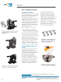
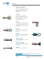
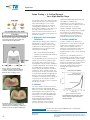
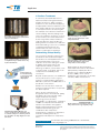
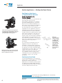
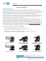
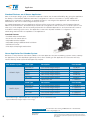
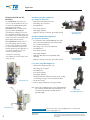
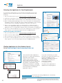
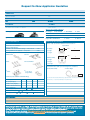
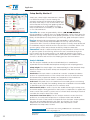
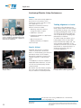
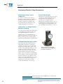
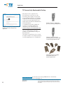
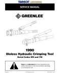
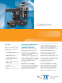
Catalog 296393-2
Revised 02-06
Applicators
Fast Facts
TE Connectivity applicators with
reliable, long-life quality and
construction for a vast variety of
terminals from TE and other
manufacturers:
• Versatile applicators for sideor end-feed terminals
• In-stock selection for over
5,000 terminal types
• Special designs to meet
unusual and international
requirements
• Highest quality replaceable
crimp tooling
• Flexible plans for ownership
or rental
• Options for fast, costeffective troubleshooting and
service
Selection, Use, Maintenance,
and Troubleshooting for
Maximum Productivity
Applicators and tooling, from TE
Connectivity, can be your key to
productive, profitable wire harness
manufacturing. These applicators
come from a long tradition of quality,
reliability, and precision.
Manufactured from high grade tool
steels, and processed through stateof-the-art CNC equipment for tightest
tolerances, TE applicators are made
for high repeatability and fast
throughput.
Every piece goes through an
exhaustive test and calibration
process, with each one shipped with
test samples verifying operation and
full documentation for operation,
adjustment, and maintenance.
TE Connectivity offers an unmatched
selection of applicator styles and
terminal types, with configurations for
both TE and other manufacturers’
terminals. Styles are available for nonTE terminating machines from both
domestic and foreign sources.
At TE we do more than supply the
world’s leading applicators. We
provide service, technical support, and
maintenance and repair, both on site
and at our service centers. We know
how critical reliable production is, and
our products and services are
committed to keeping your
production running.
We also recognize that your needs
may change quickly, so our extensive
selection of applicators is available in
flexible purchase and rental plans.
With these choices, you can manage
your costs while maintaining the
capacity and capability you need.
Applicators
Keys to Quality Crimping
Crimping Conditions
Crimp connections are the standard in
industrial manufacturing, maintaining
good connection under extreme
mechanical, thermal, and
environmental conditions. Successful
crimping results from the correct
relationship between wire, terminal,
and crimping tool. Once the terminal
selection is made and crimping
criteria defined by the connection
designer, the tooling characteristics
are fully determined.
lead-processing systems can
incorporate varying degrees of
automation, from one-at-a-time
machines, with wires hand-fed,
activated by an operator-driven foot
switch to fully automated leadmakers that cut and strip the wires,
and feed wires and terminals.
Applicators are configured by TE
according to the wire and terminal
type, and in some cases, by
the terminator specifications.
These conditions are realized in:
• Wire—conductor section and
insulation diameters and material
Successful crimping results from the correct
relationship between wire, terminal, and
crimping tool.
• Terminal—conductor and insulation
barrel crimp styles and dimensions
• Crimping equipment—settings for
wire and insulation crimp height, feed
parameters, and adjustments
Summarizing, the conductor crimp
ensures a good connection between
the wire and the terminal. The
insulation crimp supports the wire to
reduce the effects of vibration and
movement on the conductor crimp.
Terminals to be crimped in automatic
equipment are generally supplied in
continuous strips (shown here) or, in
some cases, as loose pieces.
Accomplishing the Desired
Crimp
Terminal type and wire parameters
depend on the production
requirement. Both open barrel and
closed barrel terminals are supplied on
continuous strips. Crimping is
performed by an applicator, a
mechanism that performs the
functions of feeding the terminal,
cutting the terminal from the strip,
and crimping wire and insulation.
Crimping force is provided by a
terminator in which the applicator is
mounted. Terminators and other
A terminator provides the crimping
force for the applicator installed within.
Applicators are built for specific terminal
and wire sizes and feed arrangements.
Need More Information?
2
Catalog 296393-2
Revised 10-2011
For information about tooling, call 888-777-5917 or 717-810-2080;
email: [email protected].
For drawings or technical data, contact your TE Connectivity sales engineer or call the Technical Support
Center: 1-800-522-6752. Dimensions are in millimeters unless specified otherwise. Values in brackets are
English equivalents unless specified otherwise. Specifications subject to change. Consult TE Connectivity for
latest specifications.
Applicators
Common Crimp Forms
A brief review of common wire and
insulation crimps indicates the variety
of crimping requirements that can be
implemented in TE Connectivity
applicators.
F-CRIMP
F-crimp
The most common crimp form.
Features a U-shaped open barrel,
which is closed during the crimp cycle,
pressing tightly together with the
conductor. This form is also common
as an insulation crimp.
TAB-LOK
An asymmetrical terminal, useful when
there is only a narrow space available
for the terminal. Incorporates a locking
tab to support the asymmetric forces
when it is in use.
W-crimp
Tab-Lok
W-CRIMP
Common with metallic closed crimp
barrels for both stranded and solid
conductors.
C-crimp
C-CRIMP
A metallic closure with plastic barrel on
top of it—provides good support for
insulation.
Overlap Crimp
OVERLAP CRIMP
Insulation crimp suitable for leads with
thin-walled insulation.
WRAP-OVER CRIMP
Wrap-over Crimp
An insulation crimp in which the crimp
ends “interlace,” completely enclosing
the insulation.
O-crimp
O-CRIMP
Useful for processing individual seals.
Need More Information?
3
Catalog 296393-2
Revised 10-2011
For information about tooling, call 888-777-5917 or 717-810-2080;
email: [email protected].
For drawings or technical data, contact your TE Connectivity sales engineer or call the Technical Support
Center: 1-800-522-6752. Dimensions are in millimeters unless specified otherwise. Values in brackets are
English equivalents unless specified otherwise. Specifications subject to change. Consult TE Connectivity for
latest specifications.
Applicators
Crimp Tooling — A Critical Element
for a High Quality Crimp
The crimp tooling—the actual crimper
and anvil that are in contact with the
wire and insulation—is one of the
most important factors in meeting
crimp quality specifications. TE
Connectivity quality tooling is proven
through years of experience to
achieve superior performance. Four
aspects of the crimp tooling have the
maximum impact.
The connection designer selects a terminal
and crimp parameters that achieve the
desired reduction in Area Index.
1. Geometry and Associated
Tolerances
Terminals are designed to perform to
specification only when the final
crimp form is within a narrow range
of dimensions. Controlling critical
crimp dimensions is influenced by
many factors including:
• Wire size and material variation
• Terminal size and material variation
• Equipment condition
The final quality and consistency of a
crimp can never be any better than
the quality and consistency of the
tooling that is used. If other variations
could be eliminated, tooling can and
should be able to produce crimp
forms that are well within specified
tolerances. Also, variation from one
tooling set to another should be held
to a minimum. Crimp tooling features
that are well controlled and exhibit
excellent consistency from tooling set
to tooling set can result in shorter
setup time as well as more consistent
production results.
Proper crimper and anvil design
provide necessary clearances without
excessive tolerances that can lead to
flash and other crimping errors.
(a)
terminal is plastically deformed and
extruded to complete the
termination. The anvil experiences
some of the same conditions but to a
much lower level of severity.
Specific material characteristics
bearing on the crimp process include
the toughness to withstand the
shocks generated during crimping
and sufficient wear resistance to
maintain dimensional tolerances.
3. Surface condition
Surface condition can affect the
performance of the crimp tooling as
well as the longevity of service. A
hard, smooth surface improves
adhesive wear properties and, thus,
increases service life. The other
attribute that needs to be considered
is friction.
Friction is a contributing factor in
determining the final crimp form and
process characteristics. Low tooling
friction results in lower crimping force
and thus can influence crimp form as
well as tooling life. Consistent
frictional characteristics between
tooling sets reduces process
variation.
2. Material
(b)
Significant flash can be generated with
excessive anvil-to-crimper clearance, as
illustrated by nominal-design condition (a)
and +0.003 in over nominal condition (b).
The wire crimper and the anvil have
different functional demands. Both
have the need to withstand high loads
and moderate shock. However, the
wire crimper is in fact an aggressive
forming tool. It must withstand high
shear loading that is a result of
frictional loads generated as the
terminal barrel slides along the
crimper surfaces in the forming
process, and then as the barrel
Need More Information?
4
Catalog 296393-2
Revised 10-2011
A polished, lubricated crimper surface
reduces friction and the associated
material buildup.
For information about tooling, call 888-777-5917 or 717-810-2080;
email: [email protected].
For drawings or technical data, contact your TE Connectivity sales engineer or call the Technical Support
Center: 1-800-522-6752. Dimensions are in millimeters unless specified otherwise. Values in brackets are
English equivalents unless specified otherwise. Specifications subject to change. Consult TE Connectivity for
latest specifications.
Applicators
4. Surface Treatment
A commonly accepted approach to
improved crimp tooling performance
and life has been to apply a surface
treatment to the crimp area. Applying
an appropriate surface treatment to the
wire crimper will have the most benefit
to crimp performance and tooling life.
No buildup of material is visible on a
chromium plated crimper surface after
100,000 terminations.
An example of an effective treatment is
chrome plating. Chrome plating has a
very low coefficient of friction, so there
is less tendency for terminal distortion.
It also has greater surface hardness,
reducing adhesive wear. Finally, the
plating enhances resistance to adhesion
and cold welding, so there is no buildup
of material transferred from the
terminal that can cause incorrect
crimps on subsequent operations.
Material buildup in the crimper
results in gross deformation of the
crimped terminal.
Determining Crimp Quality
Note significant buildup of material on
an unplated crimper surface after only
60,000 terminations.
Crimp height can
be measured using
a micrometer with
appropriately
shaped jaws.
The connection designer, having once
specified the wire and terminal type,
also defines the crimp parameters. The
critical characteristic is the area
reduction of the wire during the crimp.
A quality crimp must achieve the
required area reduction, without
inducing conditions, such as flash, overor under-crimp, or bending, which can
compromise the reliability of the
connection.
Beyond visual inspection, the traditional
test is pull-out force. This is a gross
measure of crimp quality, and may be
difficult to perform on a 100% basis in a
production environment.
Material buildup on the crimper results
in visible deformation of the outer
crimp surface in this example.
Crimp height can be tested with a
micrometer that has been fitted with
appropriately shaped jaws. More
effective is the TE Crimp Quality
Monitor (CQM), which can be
installed on the terminator to provide
real-time, 100% measurement.
Crimp force has also been used as a
measure, but by itself does not provide
the data required.
The TE Crimp Quality Monitor uses
sensors mounted on the terminator ram
to combine crimp force and ram position
in a calculation of crimp height on a realtime basis.
Driven by the requirements of
6-Sigma and other international quality
standards, TE has developed crimp
height measurement testing
technology, which provides
dependable, non-destructive, evaluation
of 100% of crimped terminals without
impact on production throughput.
Crimp height measurement is a well
established methodology and, in
combination with crimp force
measurement, is superior to destructive
methods, sampling methods, or
techniques that depend on crimp force
alone.
Need More Information?
5
Catalog 296393-2
Revised 10-2011
Actual real-time measurement of force vs.
ram position shows a good quality crimp.
For information about tooling, call 888-777-5917 or 717-810-2080;
email: [email protected].
For drawings or technical data, contact your TE Connectivity sales engineer or call the Technical Support
Center: 1-800-522-6752. Dimensions are in millimeters unless specified otherwise. Values in brackets are
English equivalents unless specified otherwise. Specifications subject to change. Consult TE Connectivity for
latest specifications.
Applicators
Quality Applicators — Making the Right Choice
End-Feed or Side-Feed —
A Terminal-Driven Decision
Feed Determined by the
Terminal Supply.
The two main classes of terminal feed are
side feed and end feed. This
determination depends on the terminal
geometry, stamping process, and other
factors in the terminal manufacture. In
both cases, the terminals are supplied in
a continuous strip, coiled on a reel.
In the side feed applicator, the applicator
feed strip moves perpendicular to the axis
of the individual terminals, from side to
side with respect to the operator.
End feed terminals move from the back of
the applicator toward the operator, barrel
first for manual wire insertion.
For side feed, where the terminals move
(typically) into the applicator from the
operator’s left to right, the terminals are
formed attached to a carrier strip that
includes feed holes spaced with the same
pitch as the terminals on the strip. The
axis of the terminals, i.e., the direction
that the wires are inserted for crimping, is
perpendicular to the feed direction, so
the terminals are parallel on the strip. As
part of the crimp process, the terminal is
cut free from the strip, which is
discarded.
For end feed, the terminals enter the
applicator from the rear and move
toward the operator, barrel end first. In
this case, the terminals are aligned with
the direction of motion, and have blank
metal between the front edge of one (the
crimp end) and the rear edge (the
trailing, terminal end) of the next. There
is no separate carrier. As part of the
crimping process, this small blank piece
of metal, or “slug,” is cut out and
discarded.
(a)
(b)
Side feed
terminals (a) are
made on a single
or double carrier
strip. End feed
terminals (b) are
often supplied
when the design
would use too
much metal or
have too great a
pitch if made as
side feed.
Pre-Feed or Post-Feed
In post-feed applicators, the terminal is
positioned for crimping after the operator
activates the switch. In pre-feed
applicators, the terminal is positioned prior
to crimping. This is particularly useful for
closed barrel terminals, so that the operator
can more easily insert the wire end.
Need More Information?
6
Catalog 296393-2
Revised 10-2011
For information about tooling, call 888-777-5917 or 717-810-2080;
email: [email protected].
For drawings or technical data, contact your TE Connectivity sales engineer or call the Technical Support
Center: 1-800-522-6752. Dimensions are in millimeters unless specified otherwise. Values in brackets are
English equivalents unless specified otherwise. Specifications subject to change. Consult TE Connectivity for
latest specifications.
Applicators
Choosing an Applicator
Ocean Applicator Series
With the knowledge and experience of over a half century designing and manufacturing world leading
applicators and tooling, TE Connectivity is taking terminal crimping to a new level. Using the time proven HDM
and HDI applicator platforms as a base and the innovation and improvements from the System III Applicator, TE
is taking a large step forward. TE has listened to customer input and market demands to innovate and improve
the combined strength of these industry leading designs to create the new Ocean Applicator.
The lead and harness industry of today is more price and quality competitive than ever before. Crimping
standards continue to be raised to higher levels of quality and repeatability. The industry continues to expect
more from application tooling. The new Ocean Applicator Series was designed specifically to exceed the
requirements of today and meet the demands of tomorrow.
By consolidating our applicator offering to this new Ocean Applicator, TE can provide design consistency and
tooling standardization to the market. One of the major benefits to the customer is offering the ultimate
flexibility with a choice of feeding options: New and improved Mechanical and Pneumatic feeds combined with
the innovative and precise Servo Feed option. The Ocean Series design makes it possible for customers to
perform field upgrades to System III technology. It will provide an upgrade path for terminal intelligence that
allows the machine to obtain set-up features as the applicator is upgraded. Request Catalog 4-1773460-5 for
more information about the Ocean Applicator Series or view it online at tooling.te.com/applicator.asp
One Applicator Platform — Modular Family Design
• 2 ram interface styles (“Atlantic” or “Pacific” style ram collar)
• Same wire crimper, insulation crimper, and anvil used on both applicator styles
• 3 feed options — • Mechanical
• Pneumatic
• Servo
• Same feed units can be used on Side-Feed and End-Feed style applicators. All units can be
easily removed and interchanged for upgrades if desired.
Atlantic-Style SF Servo
Atlantic-Style SF Pneumatic
Atlantic-Style SF Mechanical
Pacific-Style SF Servo
Pacific-Style SF Pneumatic
Pacific-Style SF Mechanical
Need More Information?
7
Catalog 296393-2
Revised 10-2011
For information about tooling, call 888-777-5917 or 717-810-2080;
email: [email protected].
For drawings or technical data, contact your TE Connectivity sales engineer or call the Technical Support
Center: 1-800-522-6752. Dimensions are in millimeters unless specified otherwise. Values in brackets are
English equivalents unless specified otherwise. Specifications subject to change. Consult TE Connectivity for
latest specifications.
Applicators
Standard Features on all Ocean Applicators
One of the major design goals of the Ocean Applicator Series was increased flexibility. By giving the applicator
the ability to flex between different terminator configurations it allows customers to quickly adapt their
applicators to whatever configuration is needed. All parts to reconfigure the applicator are included and
attachable to the unit for safe storage and quick access.
As standard equipment the new applicator will have all the accessories needed to switch between 30 and
40mm stroke terminators, pre-feed and post-feed cam configurations and cut and no-cut carrier options. The
wire stop / wire stripper can also be easily adjusted for the desired applications, and a mechanical counter is
included for tracking cycle counts. The applicator comes with all parts needed to configure it to any
terminating method that is acceptable to the application.
Standard Features
• Pre-feed and post-feed cams
• Cut and no-cut carrier options
• Adjustable terminal stripper
• Adjustable spring-loaded terminal hold down
• Mechanical counter
• Fine adjust crimp height mechanisms
Ocean Applicator Part Number System
Because so many features have been added to the new applicator the part numbering system used to identify
the applicators can be simplified significantly. Now, when ordering a new applicator the customer will only
need to identify what style and feed type they require.
Part Number System
Atlantic Style
Pacific Style
Feed Type
Description
Part Number
Mechanical
Fine Crimp Height Adjust
2151054-1
Pneumatic
Fine Crimp Height Adjust
2151054-2
Servo
Fine Crimp Height Adjust
2151054-5
Servo
Non-Crimp Height Adjust*
2151054-6
No Feed
Fine Crimp Height Adjust
2151054-7
Spare Parts Kit
7-2151054-7
Feed Type
Description
Part Number
Mechanical
Fine Crimp Height Adjust
2-2151054-1
Pneumatic
Fine Crimp Height Adjust
2-2151054-2
Servo
Fine Crimp Height Adjust
2-2151054-5
No Feed
Fine Crimp Height Adjust
2-2151054-7
Spare Parts Kit
7-2151054-8
* Non-Crimp Height Adjust Applicator is designed to run in a terminator with
System III Crimp Height Adjust Technology.
Need More Information?
8
Catalog 296393-2
Revised 10-2011
For information about tooling, call 888-777-5917 or 717-810-2080;
email: [email protected].
For drawings or technical data, contact your TE Connectivity sales engineer or call the Technical Support
Center: 1-800-522-6752. Dimensions are in millimeters unless specified otherwise. Values in brackets are
English equivalents unless specified otherwise. Specifications subject to change. Consult TE Connectivity for
latest specifications.
Applicators
Crimpmatic 970 and 971
Machines
Pneumatic Large Wire Applicators
(for Strip Form Terminals)
The CRIMPMATIC 970 can process
loose or reeled terminals for wires up
to 16mm2 [51/2 AWG]. Working with
even larger size wires? The
CRIMPMATIC 971 can handle all the
way up to 50mm2 [0 AWG]. But
automating the crimping process isn't
the only benefit. Crimping is faster and
more reliable. So your crimping process
will be safer and more productive, with
higher-quality finished products.
• Dedicated to Crimpmatic 970 / 971
Both CRIMPMATIC models come in a
space-saving design, have an inching
mode for setup, include a reel holder
for spooled terminals, and allow twohanded operation for the application of
loose piece terminals. You can even
order the following options:
• For terminators with standard AMP-style base plate
(4 to 8 tons) and Crimpmatic 970 with base plate
for conventional applicators.
• Crimp force monitoring
• Wire Range: up to 40, 0mm2
• Fine Adjustment
• Press Stroke: 44,0mm
• Shut Height: 158,0mm
• Applicator Feed: up to 50,0mm (pre-feed/post-feed)
Pneumatic Large
Wire Applicator
Pneumatic Mid-Size Wire Applicators
(for Strip Form Terminals)
• Wire Range: : up to 25,0 mm2 (maximum)
• Fine Adjustment
• Press Stroke: 40,0mm
• Shut Height: 135,8mm
• Fine adjustment of lower dead center
• Applicator Base Plate: Conventional Base Plate
(TE-style)
• Paper spooler
• Applicator Feed: up to 50,0mm (pre-feed/post-feed)
Pneumatic Mid-Size
Wire Applicator
Loose Piece Large Wire Applicators
• Dedicated for Crimpmatic 970 / 971
• Wire Range: up to 40,0mm2
• Fine Adjustment
• Press Stroke: 44,0mm
• Shut Height: 158,0mm
• Moveable table with dedicated terminal seat (according
to terminal geometry) to load and unload terminals
Crimpmatic 971
• Stroke: 40 to 50mm
• Custom designs available for nearly any terminal
Note: All loose piece applicators have a micro switch installed at
the end of the moveable table stroke. This allows it to be
connected in the terminator electrical system for
preventive safety.
Loose Piece
Large Wire Applicators
Crimpmatic 970
Need More Information?
9
Catalog 296393-2
Revised 10-2011
For information about tooling, call 888-777-5917 or 717-810-2080;
email: [email protected].
For drawings or technical data, contact your TE Connectivity sales engineer or call the Technical Support
Center: 1-800-522-6752. Dimensions are in millimeters unless specified otherwise. Values in brackets are
English equivalents unless specified otherwise. Specifications subject to change. Consult TE Connectivity for
latest specifications.
Applicators
Selecting the Applicator for Your Requirements
A convenient lookup function on the TE web site will guide you through
applicator selection and provide access to all necessary documents and
drawings.
1. Use your web browser to go to http://tooling.te.com/applicator.asp.
2. Under More Information, click on the link called “Tooling Cross Reference”.
3. Enter the part number of the terminal in the indicated box and click on Search.
4. On the resulting Part Detail page, click on the Tooling link in the Related Part
Information section. This page also gives complete information on the selected
terminal, with links to drawings, specifications, and other documents.
5. Click on your geographic region. You will be taken to a page that gives
references to appropriate applicators, including references for selecting an
applicator for use in a particular terminator, with documentation and drawings.
6. If you do not find an applicator to meet your requirements, contact your TE
sales engineer or the Technical Support Center at 1-800-522-6752.
Applicators for Non-TE Terminals
1. Use your web browser to go to http://tooling.te.com/applicator.asp.
2. Click on the link called :”Applicators for non-TE Terminals”.
3. Use your browser’s Search function to find the terminal you need to crimp.
4. If you do not find an applicator to meet your requirements, contact your TE
sales engineer or the Technical Support Center at 1-800-522-6752.
Finding Applicators by Part Number Search
Go to: www.tooling.te.com/europe/applicator.asp
This powerful search application
allows you to search by terminal or
applicator part number.
Simply enter the part number,
select a manufacturer from the
drop-down box and our application
will display a comparative array.
Additional information is available
via hypertext including the specific
PN’s required for the different
application options.
Need More Information?
10
Catalog 296393-2
Revised 10-2011
If you don’t find what you need,
that does not mean that there is not
anything available for your
application. Call 888-777-5917 or
717-810-2080 for personal
assistance or email:
[email protected].
The data in this application is
updated on an ongoing basis.
For information about tooling, call 888-777-5917 or 717-810-2080;
email: [email protected].
For drawings or technical data, contact your TE Connectivity sales engineer or call the Technical Support
Center: 1-800-522-6752. Dimensions are in millimeters unless specified otherwise. Values in brackets are
English equivalents unless specified otherwise. Specifications subject to change. Consult TE Connectivity for
latest specifications.
Request for New Applicator Quotation
Company Name
Customer Contact
Title
Address
City
State
ZIP Code
Phone Number
Country
Fax Number
TE Connectivity Customer Acct Number
E-Mail Address
Choose one of each category:
Ram Type:
❏
❏
Type of Terminal: ❏ TE Terminal
❏ Pneumatic
❏ Servo
Terminator Stroke:
❏ 30mm
❏ 40mm
Crimping Machine:
❏ Leadmaker
❏ Bench
Large Wire Terminator:
❏ 5 Ton
❏ 16 Ton
Feed Type:
❏ non-TE Terminal
❏ Mechanical
For non-TE Terminal Use:
Crimp Specification Information:
Terminal Manufacturer:
Indicate crimp specification dimensions and tolerances:
Manufacturer’s Part Number:
Open Barrel
(include additional info)
Terminal to be inserted into housing?
Seal or grommet to be applied?
❏ Yes, Part #
❏ Yes, Part
❏ No
❏ No
Carrier Strip Type:
❏ End-to-End
Wire Crimp:
W =
±
W =
±
❏ “F” Type
❏ “O” Type
❏ Front
Insulation Crimp:
❏ Rear
❏ Front and Rear
❏ “F” Type
❏ “O” Type
❏ “OV” Type
Reel Feed Direction (with operator facing front of machine):
❏ Rear (End-to-End)
❏ Center
❏ Left-to-Right
❏ Loose Piece
(Large Wire)
Applicator
❏ Other (Specify & attach terminal drawing)
Note: Please list and document any special crimp, cut-off, bend, housing
requirements, or special qualification requirements.
Wire Gauge(s):
Wire Crimp Height(s):
Insulation Crimp Height(s)
Insulation Outside Diameter(s):
Pull Test (Minimum):
Wire Quantity Crimped Simultaneously: ❏ Single ❏ Multiple
❏ No ❏ Yes (if yes, order 1424359-1)
❏ No ❏ Yes If Yes, ❏ Pigtail or ❏ Thru Splice
Cross Section Analysis:
Splice Application?
Special Request:
Please complete this form in its entirety. All the information is required in order to provide a quotation. Be sure to include contact
name for further communication. Submit a copy of this information, product prints, or 5 sample terminals (on carrier strip), and an
application specification or 5 properly terminated samples to your TE Connectivity Sales Representative.
Note: When an applicator is ordered, 300 terminal samples (in strip form), product prints, application specifications, and
(if applicable) 50 seals and one terminal housing must be provided for the final assembly and applicator qualification.
Applicators
Crimp Quality Monitor II
Simply put, crimp height measurement is the best
non-destructive way to ensure meeting the
stringent mechanical and electrical properties of
the crimp. New easy to use, intuitive menus along
with enhanced monitoring and graphing lead the
improved feature set of the CQM II. Another
major enhancement is the ability to use CQM II
on non-TE terminators.
Basic Analysis Monitoring
Versatile: On-screen programmability allows quick, flexible job set-up.
Enhanced ability to support the use of USB peripherals such as: flash drives for
database backup, saving reports, and updating firmware. It also includes a full
library of USB printers for easy printing of the many graph and report options.
Precise: Crimp height measurements are repeatable to within 0.12mm
(0.0005”) for every crimp analyzed. CQM II is the only crimp monitoring
system that offers continuous Crimp Height analysis for every crimp produced.
Five different analysis methods monitor the process to the fullest extent. This
ensures quality crimps are produced and faulty crimps are detected.
Crimp Height Entry
Convenient: Setup is simple and fast. Only a few parameters need to be set
to get the system up and running. All functions are controlled through the
touch screen, with an intuitive easy to use graphical interface. The system
walks you through all the required steps to start production. CQM II has more
choices to observe and monitor the crimping process than ever before.
Analysis Methods
The five analysis methods can be used individually or in combination
to provide the most flexible and complete coverage of the crimping process.
Crimp Height: The crimp height is the measured height of the terminals crimp
barrel formed around the wire. Crimps are analyzed to be within the set
tolerance zone.
Production Crimp Height
Work Index: The work index is a value that is used to compare the relative
position of a specified section of the crimp curve that occurs while the wire
and terminal are compressed. Crimps are compared to historical data to
determine pass/fail. The work index is a dimensionless value.
Peak Force: The peak force is the maximum force reading that occurs during
the crimp, minus the idle force reading. Crimps are compared to historical data
to determine pass/fail. The peak force is a relative value.
Point-to-Point (P2P): A series of points are established along the crimp curve
in the P2P analysis. During production each point is compared to its upper and
lower control limits, and if no points are out of their limits the analysis method
considers the crimp to be a PASS crimp.
FFT
Fast Fourier Transform (FFT): The FFT analysis method converts the force
profile into its component frequencies. It computes mean and standard
deviation for each of the lowest 32 frequencies from the learn crimps updates
the mean and standard deviation with each good crimp. If 4 or more
frequencies are outside the tolerance limits, the crimp status is FAIL.
Otherwise the crimp status is PASS.
Need More Information?
12
Catalog 296393-2
Revised 10-2011
For information about tooling, call 888-777-5917 or 717-810-2080;
email: [email protected].
For drawings or technical data, contact your TE Connectivity sales engineer or call the Technical Support
Center: 1-800-522-6752. Dimensions are in millimeters unless specified otherwise. Values in brackets are
English equivalents unless specified otherwise. Specifications subject to change. Consult TE Connectivity for
latest specifications.
Applicators
Continuing Effective Crimp Performance
Service
While on-site service may appear to
be the most convenient, a less
expensive solution may be to ship
your applicator to our
Applicator/Terminator Service
Center. Services include:
• Warranty Services—with no
charge for labor or parts
• Calibration Services
The Technical Support Center can provide
access to telephone troubleshooting, on-site
service, or factory-level repair of applicators
and electronic equipment.
• Equipment Repair—to application
specifications
• Quick Turnaround
• 90-day Warranty on Repairs
Technical Tips
Feed is Critical
Misfeeds are the most common
cause of production downtime.
Over- or under-feeding can result in
premature wear of the crimper,
because the terminal contacts the
crimper surface in unprotected
areas.
Tooling Alignment is Crucial
Incorrect tooling alignment can
mean rejects due to excessive flash
or terminals sticking in the crimper
and being damaged or bent. It also
can reduce tooling life, leading to
out-of-specification crimping and
premature tool failure.
A simple setup procedure, using
heavy paper such as that taken
from the terminal supply reel, can
ensure proper alignment of the
crimper to the anvil. This should be
performed on a periodic basis, or
whenever there are signs of
incorrect alignment.
The applicator must be capable of
repeatable feed distances, or both
tool life and crimp quality will be
compromised.
An over-fed terminal can scrape the entire
crimper surface.
Be certain that the feed is properly
set. Your user’s manual gives the
full procedure for feed adjustment.
Need More Information?
13
Catalog 296393-2
Revised 10-2011
When the crimper and anvil are not aligned,
it is impossible to achieve a good crimp.
For information about tooling, call 888-777-5917 or 717-810-2080;
email: [email protected].
For drawings or technical data, contact your TE Connectivity sales engineer or call the Technical Support
Center: 1-800-522-6752. Dimensions are in millimeters unless specified otherwise. Values in brackets are
English equivalents unless specified otherwise. Specifications subject to change. Consult TE Connectivity for
latest specifications.
Applicators
Continuing Effective Crimp Performance
Maintenance Keeps You in
Production
It’s easy to overlook, but routine
greasing can be a factor in reducing
production downtime. Checking
tooling—inspecting crimpers and
anvils—before they break also will
support production continuity.
Correct Shut Height
Having all your terminators set to the
correct shut height facilitates quick
change from one terminator to
another. This straightforward
adjustment procedure calls for use of
a calibrated shut height gauge. If you
cannot perform this adjustment, ask
your TE field service person to do so.
Lubrication — A Simple Step to
Reliable Crimping
Just as with any machinery, lubrication
of the applicator reduces wear and
even protects against corrosion.
Specific use of contact lubricant on
terminals prevents the friction that can
lead to sticking in the crimper, bent
terminals, and premature crimper wear.
Transporting Applicators Safely
Although they are manufactured to
withstand the impact of crimping,
crimpers and anvils do not fare well
when they contact each other. Such
contact can scrape the plating or the
crimping surface, causing a friction
point. Such a friction point can form
metal buildup, ultimately causing
reject crimps and even tool breakage.
Proper adjustment of shut height
facilitates quick change of applicators
into different terminators.
This problem is easily avoided. Always
leave a terminal in the crimp tooling
when moving the applicator from one
location to another. This allows the
terminal to receive any possible
contact and protects the tooling.
Need More Information?
14
Catalog 296393-2
Revised 10-2011
For information about tooling, call 888-777-5917 or 717-810-2080;
email: [email protected].
For drawings or technical data, contact your TE Connectivity sales engineer or call the Technical Support
Center: 1-800-522-6752. Dimensions are in millimeters unless specified otherwise. Values in brackets are
English equivalents unless specified otherwise. Specifications subject to change. Consult TE Connectivity for
latest specifications.
Applicators
TE Connectivity Replaceable Tooling
Only by the use of genuine TE
Connectivity tooling can you be
assured of the longest tool life and
most reliable production. The design,
materials, and manufacturing quality
of TE tooling translate directly into
fewer rejects and fewest breakdowns
and interruptions.
A simple cross-reference lookup will help you
find the replaceable tooling for your
application.
To determine the part number for
tooling for a specific applicator,
simply set your web browser to
www.tooling.te.com/searchparts.asp,
enter the applicator part number, and
click on Search Parts. The part
numbers of replaceable tooling will
be presented.
The same lookup allows you to enter
the part number of a crimper and find
out what applicators it is suitable for.
The wire crimper is configured for
precision positioning and adjustment.
Insulation crimpers follow the
positioning of the wire crimper, with
a separate height adjustment disc.
TE quality crimpers are available
for thousands of wire and
terminal requirements.
Need More Information?
15
Catalog 296393-2
Revised 10-2011
For information about tooling, call 888-777-5917 or 717-810-2080;
email: [email protected].
For drawings or technical data, contact your TE Connectivity sales engineer or call the Technical Support
Center: 1-800-522-6752. Dimensions are in millimeters unless specified otherwise. Values in brackets are
English equivalents unless specified otherwise. Specifications subject to change. Consult TE Connectivity for
latest specifications.
The Right Choice for Crimped Connections
With a long-standing tradition of quality, TE
Connectivity brings you a complete solution for
crimped terminal manufacturing:
• Precision applicators for nearly any terminal choice
• Crimp Quality Monitor II— to maintain the highest
quality performance and production dependability
Put TE quality crimp tooling to work in your
production. Contact the Technical Support Center at 1800-522-6752, call your TE authorized representative,
or visit www.tooling.te.com
for more information.
• Highest quality replaceable crimp tooling
• Convenient web-based tools for finding the parts for
your exact requirement
• Service and support to keep your production
running
Catalog 296393-2 / 10-11 / Application Tooling
© 2011 Tyco Electronics Corp. AMP, AMP-O-LECTRIC, AMP-O-MATIC, TE Connectivity (logo) and TE
Connectivity are trademarks. All other trademarks used are the properties of their respective owners.
Tyco Electronics Corporation, Harrisburg, PA 17105, Phone: 717-564-0100; Fax 717-986-3316
Disclaimer
While TE Connectivity has made every reasonable effort to ensure the accuracy of the information in this
catalog, TE Connectivity does not guarantee that it is error-free, nor does TE Connectivity make any
other representation, warranty or guarantee that the information is accurate, correct, reliable or current.
TE Connectivity reserves the right to make any adjustments to the information contained herein at any
time without notice. TE Connectivity expressly disclaims all implied warranties regarding the information
contained herein, including, but not limited to, any implied warranties of merchantability or fitness for a
particular purpose.
The dimensions in this catalog are for reference purposes only and are subject to change without notice.
Specifications are subject to change without notice. Consult TE Connectivity for the latest dimensions
and design specifications.