1
Deskan v7.1
Version 7.1
User Manual
Shapemakers
January 2009
The information and the software described in this document are subject to change without notification and should not be
construed as commitments by The Shapemakers for any errors that may appear in this document.
The software described in this document is furnished under a licence and may be used or copied only in accordance with the
terms of that licence.
Copyright 1991-2005 Shapemakers
29 Kensal St.,
Moorooka Q4105
Australia
Portions of the imaging technology of this product are copyrighted by
AccuSoft Corporation.
Internet:
Telephone:
Facsimile:
http: //www.theshapemakers.com
+61 (0)7 3848 7371
+61 (0)7 3848 7373
Trademarks
Deskan Express is a trademark of the Shapemakers group.
ProVec is a trademark of SInclair Knight Merz Pty. Ltd.
Microsoft, MS-DOS, Windows, and Windows NT are registered trademarks of Microsoft Corporation.
Pentium is a registered trademark of Intel Corporation.
All other trademarks mentioned in this manual are the property of their respective trademark holders.
Contents
Table of Contents
Chapter 1 GETTING STARTED
1-1
About the Manual
About Deskan v7.1
System requirements
Installation
Starting Deskan v7.1
1-1
1-4
1-4
1-5
1-5
Chapter 2 FUNDAMENTALS
2
Introduction
Files, Layers and Documents
Colour, Palettes and Transparency
Opening Documents and Layers
Printing
2-1
2-11
2-15
2-17
2-30
Chapter 3 SCANNING WITH DESKAN EXPRESS
3-1
Setting up for Scanning
Scan Documents
Scanning a Drawing
Adjustments
Care and Maintenance
Getting Assistance
3-1
3-4
3-7
3-15
3-20
3-22
Chapter 4 IMAGE EDITING
4-1
Introduction to Raster Editing
Invert
Colour and Depth Reduction
Colour Manipulation
Drawing Tools
Tool Modifiers
Using Fences
Pasting Operations
Transferring Data between Layers
Layer Separation with Selections
Simple Transformations
4-1
4-1
4-3
4-3
4-5
4-10
4-12
4-15
4-16
4-17
4-20
Chapter 5 MENU OPTIONS
5-1
File
Edit
View
Layer
Tools
Colour
Transform
Scan
Window
Help
5-1
5-3
5-6
5-7
5-8
5-9
5-12
5-13
5-15
5-15
Chapter 6 ADVANCED TOPICS
6-1
Controlled Transformations
Document Merging
Batch processing
6-1
6-10
6-11
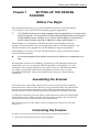
Chapter 7 SETTING UP THE DESKAN SCANNER
7-1
Before You Begin
Assembling the Scanner
Connecting the Scanner
Calibrating the Scanner with Deskan
Calibrating the Scanner using the Twain Interface
Using the Scanner: Sheet-Fed Mode
Using the Scanner: Motorized Mode
Smart Tips
7-1
7-1
7-1
7-2
7-3
7-3
7-4
7-5
Appendix A ROADMAP
January 2009
A-1
Deskan v7.1
I
Contents
Appendix B TUTORIALS
B-1
Tutorial 1: Deskan v7.1 Basics.
Tutorial 2: Colour Layers.
Tutorial 3: Selections
Tutorial 4: Monochrome Scanning
Tutorial 5: Colour Scanning
B-1
B-4
B-6
B-9
B-10
Appendix C GLOSSARY
January 2009
C-1
Deskan v7.1
II
Contents
Figures
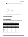
Figure 2-1. Memory Requirements (in Mb) for an A0 Image 49.61 inches wide and 34.25
inches high.
2-1
Figure 2-2. Deskan v7.1 Application Window. Note the context menu in centre of screen.
2-2
Figure 2-3 Examples of cursor types. (a) Normal (neutral) cursor; (b) Zoom 1/ Centring
cursor; (c) Zoom In/Out cursor; (d) Drawing tool cursor (Note the square at the
centre representing linewidth).
2-2
Figure 2-4. The Readout Toolbar.
2-7
Figure 2-5. A view containing some different graphic overlays. (1) Left: Control Point.
(2) Middle: Polygon Fence. (3) Right: Tracking rectangle. 2-8
Figure 2-6. Tracking facility. Note the rectangle in the right window tracking the extent of
the left window.
2-9
Figure 2-7. New Blank Layer Dialog
2-19
Figure 2-8 Save Layers Dialog
2-20
Figure 2-9. The View - Settings dialog
2-22
Figure 2-10. The Document Information Dialog
2-25
Figure 2-11. The document information dialog
Figure 2-12. “Configuration” dialog
2-26
2-27
Figure 2-13. Default save formats dialog
2-29
Figure 2-14. Sound settings dialog
2-29
Figure 2-15. The page setup dialog using paper units
2-31
Figure 2-16. The Page Setup dialog using world units
2-32
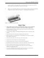
Figure 3-1. The components of the Deskan Express hardware
3-1
Figure 3-2. Attaching the scanner catch to the scanner
3-3
Figure 3-3. Scanner positioning dialog
3-4
Figure 3-4. Initial Settings Dialog
3-5
Figure 3-5. Scanning Test Strips
3-8
Figure 3-6. Control Crosses centred between Ticks on Guide.
3-10
Figure 3-7. Setting the scanning margins manually.
3-16
Figure 3-8. Adjusting scanner margins automatically
3-17
Figure 3-9. Scanner calibration
3-17
Figure 3-10. Scanner Calibration Card
3-18
Figure 3-11. Monument width calibration report.
3-19
Figure 6-1. The Helmert Transform. The dashed lines extending from the control points
indicate the relative positions of the World coordinates of each control point, and
hence the amount by which each point will be shifted under the transformation. 6-4
Figure 6-2. The Affine Transform. The dashed lines extending from the control points
indicate the relative positions of the World coordinates of each control point.
6-5
Figure 6-3. The Projective Transform. The dashed lines extending from the control points
indicate the relative positions of the World coordinates of each control point.
6-6
Figure 6-4. The “Transformation Output Settings” dialog
Figure 6-5. Document merge confirmation
January 2009
Deskan v7.1
6-8
6-11
III
Contents
Figure 7-1. Scanner connection
7-2
Figure 7-2. Deskan v7.1 scanner calibration
7-2
Figure 7-3. Twain scanner calibration
7-3
Figure 7-4. Sheet fed scanning
7-3
Figure 7-5 . Removing the scanner head
7-4
Figure 7-6. Motorized scanning
7-4
Figure 7-7. Attaching the scanner head
7-5
January 2009
Deskan v7.1
IV
CHAPTER 1
GETTING STARTED
Getting started
Chapter 1
GETTING STARTED
About the Manual
This manual contains 7 chapters and 3 appendices designed to cover every aspect of
Deskan v7.1 in such a way that the required information can be easily found. The
following descriptions provide a quick overview of each chapter and appendix.
Chapter 1
This chapter covers all aspects of getting your Deskan v7.1 system up and running
as well as describing the systems requirements and general capabilities. This
chapter is best read when you initially receive the system and before you perform
the installation.
Chapter 2
This chapter provides background information about the concepts behind the
application. Having read this chapter it is much easier to gain an understanding as
to why the application behaves the way it does.
Chapter 3
Chapter 3 describes all aspects of the scanning process within Deskan v7.1. It
covers all the available options and processes as well as reiterating on relevant
background information. Having read this chapter undertaking the scanning
tutorials will provide a confirmation on the techniques discussed.
Chapter 4
Having obtained an image this chapter deals with manipulating that image. The
topics covered involve the use of editing tools for direct adjustments; simple
transformations to adjust the whole image; and colour manipulations to modify the
appearance. It also covers methods to transfer information between layers enabling
the image to be broken down into parts.
Chapter 5
As an alternative this chapter provides a description of all the menu options. Not
only does it describe the command but it also provides descriptions on intended
uses and the best procedures to employ. There are some commands that are not
directly referenced in the earlier chapters. These commands have obvious intended
use and are fully described here.
Chapter 6
Having mastered the general use of Deskan v7.1 this chapter can now be referenced
for performing more advanced topics. The Controlled transformation provides a
mechanism to remove the more complex distortions in an image as well the ability
January 2009
Deskan v7.1
1-1
Getting started
to reference and measure the image using real world values. This works well for
planar coordinates but does not provide a true geo-referencing capability.
If the controlled transformation is being used to remove distortions then the process
can be time consuming. To reduce this problem, the process can be performed
overnight with the use of a special batch file. This is also covered in this chapter.
Chapter 7
The scanner which comes with Deskan v7.1 is also capable of being used independently by
other TWAIN compliant applications. This chapter does not relate to Deskan v7.1, but
explains how to use the scanner with other applications.
Appendix A
Appendix A contains a roadmap, which is an overview of all the functionality
within Deskan v7.1. It is used in a manner similar to an index but is grouped by
area of interest. Simply scan the main headings for the area of interest and that
group lists the capabilities and where they appear in the manual.
Appendix B
Appendix B contains a set of tutorials that provide a valuable re-enforcement to the
techniques and capabilities of Deskan v7.1. They can also be used to gain hands-on
experience. Each tutorial is aimed at a particular activity, which is identified by the
tutorial title, and in more detail in the tutorial statement of objective.
Appendix C
Appendix C contains a glossary of the terms used within the manual. This can be a
valuable aid as some terms can have multiple meanings of which only one is
relevant.
January 2009
Deskan v7.1
1-2
Getting started
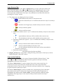
Typographical Conventions
The following text formatting conventions are used in this manual.
Text Formatting
example
Type of text item
filename.ext
<documentFileName>
File names.
Placeholders used as symbolic
names for variable items.
Menu options. Any “hot-keys” are
underscored.
User-supplied parameter option.
‘Alt-F’, ‘Ctrl-C’,
‘Shift-F1’
Key-stroke chords involving the
extended keys.
‘O’, ‘f’, ‘F1’
Single character keystrokes.
Symbol
Meaning
Warnings about various pitfalls.
Performance tips for more efficient
use of Deskan v7.1.
General note.
document_name
File – Open
January 2009
Deskan v7.1
1-3
Getting started
About Deskan v7.1
What is Deskan v7.1?
Deskan v7.1 is a powerful large-format scanning and raster editing toolkit. It
provides the tools needed to scan drawings up to A0 size (US E-size), giving an
image quality and accuracy comparable to conventional large-format scanners.
What can Deskan v7.1 do?
Deskan v7.1 has three main functions: to scan hard-copy documents into a raster
image; edit those raster images; and print those images.
Scanning a document is a simple three step process: create a "scan document"; scan
and keep the number of strips necessary to cover the document; then join the strips
to convert the scan document into a normal document containing the final image as
its only layer.
As an alternative to scanning, new blank images can be created, existing images can
be directly loaded by themselves as a new document, or if their extents match they
can be imported into an existing document. Image data can also be exported to a
large variety of raster image formats. When reading raster files the format is
automatically detected.
Once the image is obtained it can be displayed using multiple views, each with
independent zooming and scrolling. Additional raster layers can be created at
different bit depths (monochrome, 4 and 8 bit colour, 8 bit grey-scale and 24 bit
colour) and these used to break the image down into its components or trace off
information from the original. Up to 20 layers can exist within one Deskan
Document. A layer is one image in a set of images that are all overlaid.
An extensive raster editing toolkit is provided for manipulating data within the
layers. You can draw lines, rectangles, arcs and circles of pixels with the click of a
button. Pixels can be drawn or erased individually, or whole regions can be filled or
cleared. Images can be rotated, skewed and transformed using a choice of
geometric transformation operators.
When monochrome layers are involved a special tool can be used that intelligently
selects shapes from an image which can then be deleted, copied or moved.
Finally images or components can be printed out to any printer or plotter that is
supported by Windows 98, Windows 2000 or Windows XP. There is a choice of
scaling and justification options that allow for a wide choice of placement options
on the final page.
System requirements
Deskan v7.1 can be run under Windows XP or Windows Vista with a Pentium® 3
processor. Due to the large size of colour files, a minimum clock speed of 233 MHz,
minimum of 712 megabytes of RAM, and a minimum free disk space of 1 GB are
strongly recommended. A CD-ROM drive and a mouse, trackball or other pointing
device compatible with Windows XP or Vista is also required.
January 2009
Deskan v7.1
1-4
Getting started
Installation
The installation of Deskan v7.1 is a two step process involving the installation of the
Deskan v7.1 Software and the attachment and calibration of the scanner. These are
all straightforward procedures and should be easily completed in less than 30
minutes.
.
Steps for installing Deskan Express v7.1
1. Insert the CD into the CD drive.
If Autoplay does not start, then run the program D:/deskanSetup.exe.
When the Deskan Express installation appears, perform the installation and accept the
restart options.
It is very important that the scanner is positioned in the calibration cradle before
plugging the scanner in or starting the application. (The scanner will start to move. If this
happens, lift the scanner up 100mm and it should stop. Place it down in the cradle again.)
3. Connect the scanner and plug it in. A “Hardware found” dialog will appear, then
disappear.
4. If this does not occur, manually start driver setup from D:/Scanner/setup
The installation is complete.
Computer restarts…
Steps for initial configuration of the Deskan software.
5. Start the Deskan Express application.
6. Open a scan document. File/New/Scan
7. Perform the menu option “Scan – Calibrate”.
8. Using the menu option “Scan – Settings” and “Scan – Test Strip” perform a test scan to
ensure scanner is working properly.
Note: We have found the best results when we use ‘40’ on the Brightness setting and ‘60’ for
the Contrast setting.
The initial configuration is complete.
Starting Deskan v7.1
The application can be launched by selecting Start – Programs - Deskan v7.1.
Deskan v7.1 is installed with an executable named Deskan7.1.exe.
In addition, if no previous association had been set up between raster file types and
any application programs, then Deskan v7.1’s setup will introduce a default
association, allowing you to double-click on any raster file in Explorer to open the
file in Deskan v7.1.
When Deskan v7.1 starts up, you will see the Deskan v7.1 Application window
with three menu options: File, View and Help.
January 2009
Deskan v7.1
1-5
Getting started
If desired, Deskan v7.1 can be started with the name of a document, standard raster
file or Deskan v7.1 batch file as a command line parameter. Deskan v7.1 will then
start with the document or image already opened. Once Deskan v7.1 is running
additional raster files can be opened using drag and drop.
The rest of this chapter is designed to help you become productive with Deskan
v7.1 as quickly as possible.
Since you will no doubt have many questions about what Deskan v7.1 can do and
how you can get Deskan v7.1 to work for you, a section called “Roadmap” is
provided (see Appendix A). The Roadmap is a flowchart designed to help you
navigate your way through a Deskan v7.1 session, bringing to your attention
Deskan v7.1’s useful features just as you need them.
In addition, some extra tutorials are provided. All the example files required by the
tutorial will be found on the distribution disks and will have been installed into the
Deskan v7.1 directory.
To make the most of the tutorials and to assist you in using the rest of the manual,
please refer to the “Chapter 2.
January 2009
Deskan v7.1
1-6
CHAPTER 2
FUNDAMENTALS
Fundamentals
Chapter 2
FUNDAMENTALS
Introduction
This chapter provides background information about the concepts behind the
application. After reading this chapter, it will be easier to understand why the
application behaves the way it does.
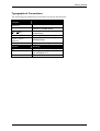
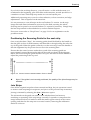
Image Sizes
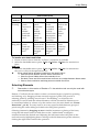
One of the most surprising things to new users is the size of the images that are
used within Deskan v7.1. Even when dealing with monochrome images the
memory requirement will rapidly increase as either dimension is increased. Using
larger bit depths will further compound these requirements. Figure 2-1 illustrates
the size of the image when held in memory for large A0 (US E-size) images. The
size of the image when stored on disk can differ, dependent on the data content and
the compression scheme used. It is important to be aware of these sizes as they
reflect the amount of data that gets transferred within the system during processing
and therefore have a dramatic influence on performance.
(A0 - U.S E) Size Images
Resolution (dpi)
100
200
400
Depth
1 bit
2.0
8.1
32.4
4 bit
8.1
32.4
129.6
8 bit
16.2
64.8
259.3
24 bit
48.6
194.5
777.8
Figure 2-1. Memory Requirements (in Mb) for an A0 Image
49.61 inches wide and 34.25 inches high.
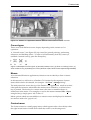
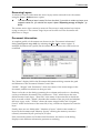
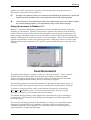
Deskan v7.1 Application Window
The Deskan v7.1 Application Window is the main window which opens when
Deskan v7.1 is started. It contains a main menu bar across the top of the window
from which all the functions of Deskan v7.1 can be invoked.
The main working area of the application window is where the client windows
containing different views of a document are confined ( See Figure 2-2, p 2-2).
Mouse usage
Deskan v7.1 supports any Windows-compatible mouse.
The left button is used for selecting, dragging, and controlling drawing tools such
as the free-hand drawing pen and eraser.
The right button is used as a reset button, a way of zooming out of the image and as
a means of summoning a popup “context” menu (See “Context menu”, p 2-2 ).
The scroll wheel allows zooming in and out.
January 2009
Deskan v7.1
2-1
Fundamentals
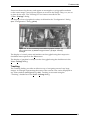
Figure 2-2. Deskan v7.1 Application Window. Note the context menu in centre of screen.
Cursor types
There are several different cursor shapes, depending on the current tool or
operation.
A “Normal cursor” (see Figure 2-3 (a)) is used for general pointing, performing
selections, and defining fences. To remove all functionality from any cursor (to
establish a neutral cursor), press the Escape key.
Figure 2-3 Examples of cursor types. (a) Normal (neutral) cursor; (b) Zoom 1/ Centring cursor; (c)
Zoom In/Out cursor; (d) Drawing tool cursor (Note the square at the centre representing linewidth).
Menus
As in standard Windows applications, functions are invoked by a chain of menu
selections.
In this manual, we will refer to a Deskan v7.1 function by the sequence of menu
items which need to be selected, for example: “the View - Settings dialog”.
The main menu bar across the top of the Deskan v7.1 Application window invokes
other pull-down menus when either the menu item is clicked on, or when its hotkey is pressed. The hot-key for a menu item is the letter or number shown in
underscore in the menu. For example, to invoke the menu command File - Open
using hot-keys, simply press ‘Alt-F’ then ‘O’.
Menu options which are unavailable in a certain context are displayed in dimmed
text and are said to be “greyed out”.
Context menu
The Context menu is a small popup menu, which appears after a short delay when
the right mouse button is held down while the cursor is on the image area.
January 2009
Deskan v7.1
2-2
Fundamentals
It contains four options which vary according to the current function (see Figure
2-2, p 2-2). For example, if the current function was zooming in and out, the menu
options are: “Zoom Out”, “Zoom In/out”, “Zoom One” and “Settings”. If the right
button was being used in reset mode (to back out of some operation), then the first
option in the menu would be “Reset”.
There is a user-definable delay between pressing the right button and the
appearance of the popup menu, in order to allow the user to quickly click the right
button to reset or zoom without the menu appearing.
If the delay is too short and you can’t click fast enough to avoid the menu, you can
alter it by selecting the File - Set Up menu option and increasing the “Context
Menu Delay (Millisec)” input field to a suitable value.
In any case, if the menu does appear unintentionally, it will contain the current
right-button operation as the first option, so all you need do is to select that menu
option.
Dialogs
Some menu items invoke sub-windows called dialog boxes which accept user
input, either by typing in values, or by selecting items or clicking buttons with the
mouse.
Status Bar
The status bar is the strip along the bottom of the main Deskan v7.1 Application
window (see Figure 2-2, p 2-2). It displays several helpful pieces of information in
its four fields.
The rightmost field represents the current Zoom level. It always contains a ‘Z’ and a
positive or negative zoom factor.
The next field to the left indicates current line weight, drawing (freehand) size or
eraser size.
The left two fields are used in various ways: prompting the user to carry out certain
tasks, displaying the current raster editing tool, and displaying the progress of
certain activities.
The display of the status bar can be toggled by selecting the checkable menu option
View - Status Bar.
Icons and Toolbars
Icons provide a convenient shortcut to access many of Deskan Express’s functions.
Icons generally have a one to one correspondence with menu selection sequences.
Fly-over hints (“tool-tips”) provide a clue as to the function of each icon when the
cursor passes over it.
Icons are arranged in groups, called toolbars. Toolbars are classified according to
the general usage of the icons it contains, for example, the “Edit” toolbar invokes
raster editing functions.
January 2009
Deskan v7.1
2-3
Fundamentals
Toolbars can be displayed or hidden using the View - Toolbars - “Toolbars
Selection” dialog. They can also be dragged around the Application window with
the mouse by grasping them by the edge, and “docked” onto the frame of the main
window by running the toolbar onto the frame. By grasping the side or bottom of
the toolbar it is also possible to adjust the toolbars dimensions.
Windows and Views
Deskan v7.1 has a main Application window which contains all other subwindows. Some sub-windows are dialog boxes, while others contain a portion of an
image. These image windows are known as “views”.
Deskan v7.1 can maintain multiple views of a document up to a limit of 10 views
per document. It can also operate with multiple image files (documents). The
current view is the window which has the input focus, recognized by its
highlighted title bar. Each view window in Deskan v7.1 has a title bar containing
the document name and the current active layer name, and, if multiple views are
open, the view number in the format: “Document_name: Layer_name:
view_number”.
The view_number field is visible only if multiple views on the same document are
open.
Documents and layers will be treated in some depth in later sections of this manual.
A view can be made current by clicking on it with the left mouse button, or by
selecting it from the most recently used list in the Window pull-down menu.
Opening Windows
When a file is loaded, at least one view of the data is created.
A new window (view) can be opened at any time by selecting the Window - New
Window menu option. The new view appears superimposed on the original, and
becomes the current view.
Arranging Windows
Windows can be moved around and re-sized by using the cursor. Windows can be
“gripped” by the title-bar and dragged with the cursor by holding down the left
mouse button.
Windows can be re-sized by bringing the cursor close to a corner-point or edge, and
when the cursor changes into a “two-way arrow”, that corner or edge can be
dragged by holding down the left mouse button, stretching or reducing the
window.
Multiple windows can be neatly arranged automatically by selecting either the
Window – Tile – Vertical, Window – Tile – Horizontal or Window - Cascade
menu options.
Scrolling (panning)
Views can be scrolled (panned) or zoomed individually. Deskan v7.1 provides a
variety of ways of doing this. To scroll a view horizontally or vertically, the
scrollbars in each view window can be used.
January 2009
Deskan v7.1
2-4
Fundamentals
The arrow keys can also be used to scroll an image. Holding down the Shift key
while using the arrow keys increases the scrolling steps.
The Home, End, Page Up, and Page Down keys also provide an efficient
mechanism to reach the top, bottom, left and right edges (respectively) of the
image. This is particularly useful for large images.
Another useful tool for scrolling an image is the centring facility, selected with the
View - Centre menu option, or its equivalent icon. Selecting centring causes the
cursor to change shape while inside the image area to four inward arrows (see
Figure 2-3 (b), p 2-2). Placing this cursor anywhere on the current view and leftclicking centres the view on that position, if it is not too close to the image
boundary.
Zooming
Zooming means making an image appear closer (Zooming In) or further away
(Zooming Out).
Zooming doesn’t affect the actual raster image, it merely changes its appearance on
the screen.
Each view can be zoomed independently.
The zoom factor is an indication of the number of screen pixels being used to
represent one data pixel.
The zoom factor of the current view is displayed in the status bar field with a ‘Z’ in
front.
Positive zoom factors magnify the image, whereas negative zoom factors make the
image look smaller. At a zoom factor of +1, one pixel in the data is displayed as one
pixel on the screen.
At a positive zoom factor the screen image will be enlarged relative to the original
scanned document by the ratio of the screen pixel size to the scanner’s pixel size.
Hence, the screen will show only a small part of the whole image. When a new
raster image is first displayed it is shown at a zoom factor of one. This is indicated
on the bottom status line of the screen by “Z+1”.
If the zoom factor is +2, then one data pixel is displayed as a block of 2 by 2 screen
pixels. Similarly, for a zoom factor of +4, one data pixel becomes a block of 4 by 4
screen pixels.
The highest possible positive zoom is +8.
A zoom factor of -2 means that a block of 2 by 2 data pixels are squeezed into one screen
pixel.
Possible negative zoom factors are: -2, -4, -8, -16, -24, -32, -40 and so on in multiples
of eight until the entire image is fitted in the view.
How to Zoom:
It is possible to zoom in two ways.
1. Use scroll wheel on the mouse to zoom in or out.
January 2009
Deskan v7.1
2-5
Fundamentals
2. In order to zoom, Deskan v7.1 must be in Zoom mode, indicated by the “Four
Arrows” cursor shape and the text “Zoom I/O” displayed in the status bar. There
are a number of ways of enabling and disabling zoom mode.
One way is to use the checkable menu option View - Zoom In/Out.
When this menu option is checked, zoom mode is active. The zoom mode is toggled
each time the option is selected.
Zoom mode can also be toggled by selecting the Zoom - In/Out option from the
context menu. Hold down the right mouse button until the menu appears, and
without releasing it, highlight the “Zoom In/Out” option. Release the button to
select. The tick beside the option means zoom mode is active, also indicated by the
cursor shape and the message in the status bar.
A third way of toggling the zoom mode is using Deskan Express’s Quick-Keys
facility. Quick-keys are a fast way of selecting main menu items with a single userdefined keystroke. A number of frequently-used menu items have had Quick-keys
pre-assigned for your convenience, one of which is ‘z’ which invokes the View Zoom In/Out option.
Once in zoom mode, make sure the cursor is on the image and click the left button
to zoom further in and the right button to zoom out. The portion of the image
under the cursor at the time it was zoomed becomes the new centre of the view,
unless the cursor was too close to the edge of the image.
Canceling Zoom mode:
Cancel zoom mode by pressing the escape key, or by reselecting the Zoom - In/Out
menu options, or by pressing the zoom Quick-Key.
The escape key has the added functionality in that it also removes any currently
selected editing tool.
Zoom 1 and Fit
There are two Zoom levels which are used frequently enough to warrant their own
special commands: these are Zoom level 1 (Zoom 1) and the maximum negative
zoom level (Fit).
A zoom level of one means that one pixel displayed on the screen equals one pixel
in the image data. After selecting View - Zoom 1, the cursor changes to the “4
inward arrows” shape. Place the cursor on any point in the current view and click
the left button. The view adopts a Zoom level of 1, centred, if possible, on the
clicked point. Zoom 1 is also available on the context menu.
Selecting View - Fit (or pressing the ‘f’ Quick-Key) immediately zooms out enough
so that the entire image can be seen.
Resolution
Resolution is a measurement of the coarseness of the scanning process, which
produced a raster image.
It is defined as the number of pixels in the image representing a certain distance on
the scanned paper. In Deskan Express, resolution is expressed as “dots per inch”
(dpi).
January 2009
Deskan v7.1
2-6
Fundamentals
A typical value is 200 dpi, which is offered as the initial default resolution when
creating a new document.
The default resolution offered when creating a new document is user-definable (see
“Configuration” dialog, p 2-26 ).
When a new document is created, the user is presented with a dialog box showing
default values for the height and width of the new image in pixels and its resolution
in dots per inch. These can be altered if necessary. Thus all documents in Deskan
v7.1 have a resolution defined.
ReadOut
The ReadOut utility is a specialized toolbar which displays image measurement
information. It has two list boxes, one for display options, the other for units as
shown in Figure 2-4.
Figure 2-4. The Readout Toolbar.
The “Coordinates” display option makes it display the current cursor image
coordinates.
The “X/Y Deltas” option displays the x- and y- components of the distance of the
cursor from the point where the left button was last pressed.
The “Distance” option displays the distance between the cursor and the last point in
the image where the left button was pressed. The first point is selected by clicking
the left mouse button in the image on a point of interest. Position the cursor on the
second point of interest, and the distance is displayed.
All the display options can be shown in the following units: pixels, inches,
millimetres, centimetres and World units.
To open the ReadOut utility:
1.
2.
Select the View - Toolbars menu option.
Check the “ReadOut” checkbox, then click “OK”.
Graphical Overlays
A graphical overlay is an object which appears in the view window but is not
actually part of the raster image. There are several different kinds of graphical
overlays in Deskan Express:
•
•
•
Fences
Tracking box
Control points and markers
January 2009
Deskan v7.1
2-7
Fundamentals
Fences are drawn by the user, and appear as rectangular or polygonal boundaries
on the raster image. Control points appear as crosses in the image. They, too, are set
in place by the user. The Tracking box is a feature controlled in the
“View - Settings” dialog.
The display colour of graphical overlays is defined in the “Configuration” dialog
(see “Configuration” dialog, p2-26).
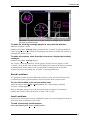
Figure 2-5. A view containing some different graphic overlays. (1)
Left: Control Point. (2) Middle: Polygon Fence. (3) Right: Tracking
rectangle.
The display of control points and markers can be toggled using their respective
checkable menu options in the View menu.
The display of graphical overlays can also be toggled using the checkboxes in the
View - Settings dialog.
Tracking
The Tracking facility provides an effective way of navigating around very large
images. A rectangle representing the extent of the current view can be displayed in
any other window (see Figure 2-6, p 2-9). Tracking is activated using the
“Tracking” checkboxes in the View - Settings dialog.
January 2009
Deskan v7.1
2-8
Fundamentals
Figure 2-6. Tracking facility. Note the rectangle in the right window tracking
the extent of the left window.
To make the tracking rectangle appear in any particular window:
Make the window current.
Summon the View - Settings dialog and check the “Current” Tracking checkbox.
Click “Accept”. Now this window will display the extent of whichever window is
subsequently made current.
To make all windows, other than the current one, display the tracking
rectangle:
Summon the View - Settings dialog.
The “Other” Tracking checkbox will be greyed. Click it twice to check it. Click
“Accept”. Now all the other windows will display the extent of whichever window
is subsequently made current. This is equivalent to making each of the other
windows current and ticking the “Current” Tracking checkboxes.
Saved Locations
It is possible to name and store different locations (zoom levels and centre pixel
coordinates) in each open document, and reconstruct these locations later.
To save the location in the current active view:
Select the menu option View - Save location. The “Enter name to identify
Location” dialog appears.
Enter a character string of up to 20 characters (with no spaces or commas) to
identify the location, then press Enter or click “OK” to save.
Load Locations
Previously saved locations can be recalled by name, reconstructing the zoom level
and centre pixel coordinate of the scene.
To load a previously saved location:
Select the menu option View - Load location.
January 2009
Deskan v7.1
2-9
Fundamentals
In the “Select location to match” dialog, select the required location from the
picklist and click “OK” to return to it, or “Delete” to delete it from the list.
Previous locations
Each time a view is zoomed, scrolled or re-sized, the location in the image just prior
to the zoom and scroll action is stored, and can be returned to using the menu
option: View - Previous location.
Each open document in Deskan v7.1 has only one storage buffer for Zoom, Scroll
and re-size events. This means that locations stored for one view will be lost if
another view of the same document is activated and Zoom, Scroll or re-size actions
are performed.
January 2009
Deskan v7.1
2-10
Fundamentals
Files, Layers and Documents
Supported File formats
Deskan v7.1 can interpret and output a number of different image file formats.
The Raster file types supported by Deskan v7.1 are:
•
•
•
•
•
Adobe Photoshop (*.psd)
•
•
•
•
JPEG File Interchange Format (*.jpg)
•
•
•
•
•
•
•
•
•
•
Brooktrout format (*.brk)
CALS raster Type 1 (*.cal) with CCITT Group 4 compression
Electronic Art’s Interchange File Format (*.iff) with RLE compression
Image Object Content Architecture (*.ica) compression formats:
CCITT Group 3
CCITT Group 4
IBM MMR
Macintosh PICT format (*.pct) with packbits compression
Microsoft Windows Bitmap (*.bmp) uncompressed and RLE compression
Mixed Object Document Content Architecture (*.mod) with compression formats:
CCITT Group 3
CCITT Group 4
IBM MMR
Multipage PCX format (*.dcx) with RLE compression (Only the first page is supported)
NCR (*.ncr) with CCITT Group 4 compression
PC Paintbrush PCX format (*.pcx)
Portable Bitmap File Format (*.pbm) in both raw and ASCII encoding
SGI Image File Format (*.sgi)
Sun Raster Data Format (*.ras) with REL compression
Tagged Image File Format (*.tif) of various compression formats:
Uncompressed - Requires lots of storage space
Packbits - Fastest to load and save
Group III - Higher compression ratio
Group IV - Very high compression rates but slower to load/save.
Huffman
JPEG
Truevision Targa (*.tga)
Windows Clipboard (*.clp) uncompressed
Windows Metafile (*.wmf)
What’s a Layer?
Deskan v7.1 supports multi-layer raster images. In many CAD packages, a single
drawing may contain multiple, superimposed layers, with each layer holding a
different subset of the vector elements in the image.
January 2009
Deskan v7.1
2-11
Fundamentals
In Deskan Express, multiple layers are implemented as separate raster files of equal
extents.
Layers should not be confused with Views, which are simply different
representations of the same document. Layers are stored as separate raster files.
The use of multiple layers may impose significant memory and performance
overheads with large raster images.
What’s a Document?
In Deskan Express, each layer is stored as a separate raster file. In order to keep
track of this multiplicity of related image files, the concept of a Document is used.
A Document is a collection of one or more raster files, plus a housekeeping file
called a Raster Control File (RCF) which logically ties them all together.
It is useful to visualize a document as a stack of transparent films. Each film
represents a single layer. A view displays what would be seen if one looked down
through the stack of films through a rectangular viewing window. The image
elements in each layer are seen superimposed in the view window.
All files comprising the document have a common path (they must all reside in the
same directory) and all have the same base file name, but unique extensions.
No more than one raster file in a document may have a standard raster file
extension (such as .pcx or .tif). All other raster files in the document have a .Lxx
extension, where xx is a number from 01 to 99.
A Deskan v7.1 document may contain up to 20 layers. Layers have unique titles up
to 20 characters long (no spaces or commas), which the user is prompted to input
whenever a new layer is created.
What’s an RCF?
The Raster Control File (RCF) is an ASCII-format file which contains housekeeping
information about the document.
If the RCF is deleted or moved to a different directory away from its raster files, the
document no longer exists.
Because of the close association between a document and its RCF, it is sometimes
convenient to refer to them interchangeably, for example, “opening an RCF” is
equivalent to “opening a document”.
Raster Control Files are used for both single- and multi-layered documents.
The information held by the RCF file includes:
•
•
•
Layer information. For each layer in the document, the RCF lists that layer’s format, title,
current drawing and background colour, and a flag indicating active/target status.
Transformation control information such as control point details, transformation type
and output settings.
Last-used view centre coordinates and zoom level, for saving and restoring the window
layout.
January 2009
Deskan v7.1
2-12
Fundamentals
•
•
•
•
Scanning status information.
Saved fences
Saved locations.
The documents palette information.
Deskan v7.1 will normally create a Raster Control File automatically, when a raster
file is open.
The only situation in which a Raster Control File is not kept after a document is
closed is when a raster file is opened but no modifications are made and the
command File - Save has not been specifically called. This allows Deskan v7.1 to be
used to view various raster files, scrolling and zooming around in them and then
closing them, leaving no unwanted RCF files on the disk.
What’s an ADF?
A second type of special file used by Deskan v7.1 is a file with the extension “.adf”.
The extension stands for Auxiliary Data File and the file is used to store ancillary
information as required. The data within the file is in ASCII format similar to an
“.ini” file and Deskan Express uses this form on two occasions.
The first case is to store fence information when a fence is saved to a file. In this
case the filename used matches the name used to store the raster information. If the
file becomes lost or is deleted, the stored image can still be pasted back into another
document however the dynamic fence used will be a rectangle representing the
extents of the image. If the file is retained and contains a polygonal fence definition
that that fence will be displayed.
The second case is to store palette information when requested by the command
Colour - Save Document Palette. In this case the file will contain 256 lines with
each line representing one colour from the palette.
Active Layer
At all times, exactly one layer in the image is designated as the “active” layer,
although the particular layer in this role can be changed (see “Layer control
buttons”, p2-23).
The active layer is the layer in which all raster editing operations take place.
The Raster Control File records the identity of the current active layer, and so it can
remember which layer was the active layer at the time the document was saved.
Target Layer
One layer in the document can be nominated as the “Target” layer (see “Layer
control buttons”, p2-23). It is the destination layer for Cut/Copy to Target and
element selection commands.
A document need not always have a designated target layer. This is important to
realize, since some operations, (such as the Tools - Do Select - Move/Copy
Selections commands), are not available unless a Target layer is defined.
January 2009
Deskan v7.1
2-13
Fundamentals
These options will be greyed-out (unavailable) until a Target layer is selected.
When a document is saved, the identity of the current target layer is not recorded,
hence a newly opened document has no target layer.
Having the layers toolbar displayed makes it very easy to change both the active and
target layers.
Having the tools toolbar displayed means that the active layer’s defined background
colour and the document’s background appearance colour can be easily referenced.
January 2009
Deskan v7.1
2-14
Fundamentals
Colour, Palettes and Transparency
Colour
Within Deskan v7.1 each layer can be one of the following:
•
•
•
•
•
Monochrome
4 bit colour
8 bit colour
8 bit grey scale
24 bit colour
These layers can be grouped into three types : monochrome layers which have no
stored palette; 4 bit colour, 8 bit colour, and 8 bit grey scale layers which have their
own palette; and 24 bit colour layers that have no palette.
Monochrome
With monochrome images there are only two possible pixel values and they are
fixed as data and background. Because of this they have no palette and are
subsequently treated differently to the other types of layers. In short the data will
always be shown in the drawing colour (see “Error! Reference source not found.”, p
4-10) and the background will always be shown in the base colour (see “Colour Base Colour - Select”, p 5-11).
4 bit and 8 bit colour
These layers both have a palette (see “Layer and Document Palettes”, p 2-16) with
the 4 bit containing 16 colours and the 8 bit containing 256 colours. As they have
their own palette every entry in those palettes will match an entry in the document
palette. If the 4 bit layer is created within the document its palette will be a copy of
the default 4 bit palette. It should also be noted that for 8 bit layers the layer palette
and document palette will contain the same entries but the order of the entries may
differ. 4 bit colour layers also have their own default palette which can be
customized (see commands Colour - Edit Default 4 bit palette and Colour - Save
as Default 4 bit)
8 bit Grey scale
An 8 bit grey scale layer contains a palette with 256 entries (see “Layer and
Document Palettes”, p 2-16). For every entry the red, green, and blue intensities
are all equal and the entries are ordered so that the RGB (0,0,0) (see “Layer and
Document Palettes”, p 2-16) is at entry 1, RGB(1,1,1) at entry 2 and so on up to
entry RGB(255,255,255) in entry 256. Because of these requirements it is not
possible to have both a grey scale layer and a 4 bit or 8 bit colour layer in the same
document. It should also be noted that the layer palette and document palette will
be exactly the same.
24 bit Colour
A 24 bit layer does not contain a palette as each pixel is fully defined. Within
Deskan v7.1 selecting a drawing colour is initially done from the document palette
which provides the 256 most often used colours and from there custom colours may
be selected if necessary.
January 2009
Deskan v7.1
2-15
Fundamentals
When you have a document containing multiple overlaid layers that may be colour,
then some rules need to be established so that it does not become too confusing.
This is accomplished by addressing three issues being palettes, transparency, and
monochrome images.
Layer and Document Palettes
A palette is a table of colour descriptions that is used by the computer to define
how a colour is to appear. Each colour is described by values for its red, green, and
blue components. This is referred to as the RGB for a colour and is commonly
documented as RGB (red value, green value, blue value). The range of the value for
each component is from 0 up to 255, with 0 meaning no contribution, and 255 being
maximum contribution. The colour red is defined as RGB(255,0,0) meaning
maximum red, and no blue or green. The number of entries in the palette for a 4 bit
image is 16, while an 8 bit image contains 256 entries.
Besides the palettes that may exist within the layers we also have one 256 colour
palette that exists within each document. This complexity is reduced by ensuring
that every colour that exists in a layer palette must exist in the document palette.
This means that there is at most 256 colours that exist within palettes within one
document. One restriction due to this is that a grey scale layer can exists in a
document only if that document contains at least one grey scale layer and
optionally monochrome layers.
The relationship between the document palette and layer palettes is always
maintained resulting in the following actions:
When a layer is imported its palette is modified to match the document palette.
This is done in a way that minimizes the visual impact on the layer.
When a fence is pasted into a layer the data within the fence is adjusted to match
that layers palette.
The manipulation of colour in relation to scanning is treated in “8 bit Colour
Scanning”, p 3-6 and the adjustment of colour data is treated in “Colour
Manipulation”, p 4-3.
Transparency
Within Deskan v7.1 the term transparency relates to one colour within each layer
(called the background) that can be treated as transparent. This makes it possible to
view information that exists on layers that are below the current active layer. To
visualize this, consider a diagram that contains three colours but has been produced
with each colour being drawn on a separate piece of clear film. When the pieces of
film are overlaid the diagram appears complete. In this case the film is transparent.
If, however, the three pieces of film were scanned into Deskan v7.1 then we would
have the same information but the clear film is now white. By defining the white in
the scanned images as the background and switching transparency on we can then
see the complete diagram.
Another colour that is related to transparency is called the “base colour” and is set
for the document. This is the colour that will appear in the image where all the
layers in the document are transparent. Again consider the three pieces of film in
the above example. If they were placed on a table then the base colour would be
January 2009
Deskan v7.1
2-16
Fundamentals
the colour of the table. In normal usage with colour layers this would be set to
white and the defined background on each layer would be set to white. In this way
any information on any layer that is not white (or covered) will be visible and the
chance of confusion will be minimized.
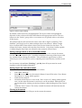
Opening Documents and Layers
When you initially start Deskan v7.1 , the main menu is limited to three items: File,
View and Help.
In order to use Deskan Express, a working file or document must be “opened”
using the File - Open or created using the File - New menu options.
Opening a file
The File - Open options allows you to select an existing raster file or Raster Control
File for input.
We say that a document is “open” when its Raster Control File has been read by
Deskan v7.1 and its housekeeping information assimilated.
While a Raster Control File is open in Deskan v7.1, that fact is recorded in the RCF,
and any attempt to reopen the same file will result in a warning dialog appearing.
When a document is opened, Deskan v7.1 loads the raster file of one of the
document’s layers into memory, so it can be displayed or edited. A layer loaded
into memory is said to be “Open”.
Other layers in the document can be opened later using either the Layer - Open or
View - Settings commands.
Different layers can be opened and closed (released from memory) while the
document remains open. While a document is open, at least one of its layers (the
“Active” layer) is open.
If a Raster Control File is selected from the File - Open dialog, its housekeeping
information is read by Deskan Express. The last active layer in the document is then
loaded into memory and displayed.
If the file you selected in the File - Open dialog is one layer of a document, opening
it will make Deskan v7.1 read the Raster Control File for that document, and load
up the selected raster file as the active layer.
If the file you select from the File - Open dialog is a raster file which is not part of
any document, then it is loaded into memory as the active layer of a new document.
If you try to open a raster file that has the same name as an existing Raster Control
File, but is not part of that document, the open will fail. The only way to open it
would be to move the raster file to another directory away from the Raster Control
File of the same name.
If you selected a Raster Control File that contains an unfinished Deskan scanning
session, the new window will be empty and certain Deskan v7.1 menu options will
be unavailable. You will be able to scan further strips or join existing ones (see “S”,
p 3-1).
January 2009
Deskan v7.1
2-17
Fundamentals
If the RCF or any of its associated raster files are read-only (for example, if they are
being read from a CD-ROM), the entire document is read-only. Any operation
which attempts to write back to these files, (e.g. File - Save, Layer - Save, etc) will
be unavailable.
Canceling File opens
To cancel a File opening operation while the file is being loaded, press the ‘Escape’
key. This may be useful where a large file has been opened by mistake. For
example, large files in certain highly compressed file formats, such as TIFF Group
IV, may take considerable time to load into Deskan v7.1.
Creating a new blank document
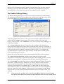
To create a new file from scratch select File - New - Blank or the equivalent icon.
A dialog titled “Create New Document” appears, asking for values for image Width
and Height in Pixels, Resolution in Dots per inch, bit depth as the number of bits
per pixel, and Layer Title. There is also a toggle available to create the layer as grey
scale. Default values for these parameters of 640, 480, 200, 8 bit, non grey scale and
“New_Layer” respectively are offered. Edit the values if desired and click OK to
accept.
A second dialog, the “Select Raster Document Name” dialog, prompts the user to
input a new Raster Control File name, select the directory to put it in and declare
the name to be used. Click Save. A new blank window appears.
If you specified the Width or height of the image to be greater than 65535 pixels, you
will not be able to select PCX format when saving.
The format for the layers is defined when the layer is being saved.
A Raster Control File having the filename that was selected above and a “.RCF”
extension is created. A raster file with the new document name and the extension
appropriate to the selected raster file format is written out to disk on saving or
closing.
Creating a new blank document for scanning into.
The menu option File - New - Scan creates a new blank document for use with the
Deskan scanning facility.
A Deskan document is a special kind of document into which images are scanned
during the scanning process.
It enables the raster image to be scanned in strips which are later joined to form the
final raster document.
Scanning is treated in more detail in the section “S”, p 3-1.
Adding new layers to a document
New layers can be added to a document by using the Layer - New options. If a new
blank layer is required, select Layer - New - Blank.
You will be presented with an “Add New Layer” dialog, where you can accept the
default layer title: “New_Layer_nn” where nn is a unique number, or choose your
own title (up to 20 characters with no spaces or commas).
January 2009
Deskan v7.1
2-18
Fundamentals
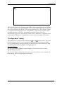
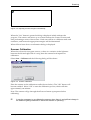
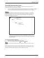
Figure 2-7. New Blank Layer Dialog
This dialog also allows you to specify the new layer as being the active or target
layer as well as specifying the bit depth and grey scale characteristics of this new
layer. The new layer is marked as being modified, meaning you will be prompted
to save it on closing the document.
It will be given the filename made up of the document name with a “.Lxx” extension,
where xx is a number.
Importing raster files as new layers
An existing raster file can be imported as a new layer, as long as it is of the same
dimensions as the other raster files in the document.
New layers imported from existing raster files are copies of the original files, and
have a .Lxx extension, where xx is a number.
To import a file as a layer, use Layer - New - Import. You will be given a fileopening dialog to choose a raster file. Select a raster file and click Open. Deskan
v7.1 will make a copy of the imported file for inclusion in the current document,
leaving the original intact.
The name of the selected file is used as the layer title and the complete path of the
original file is stored as the source for that layer.
If no target layer is specified in the current document, the newly imported layer
becomes the target, and is marked as being modified.
Saving/Closing Documents and Layers
After you have finished working on your document , you can save either one or all
of the layers back to the same document or into a new document.
Whenever layers are being saved, a list of layers is displayed, allowing individual
layers to be selected and their formats to be altered.
January 2009
Deskan v7.1
2-19
Fundamentals
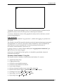
Figure 2-8 Save Layers Dialog
By default, some layers may be highlighted. The layers which are highlighted
depends on the context and will be described in the appropriate section. The two
buttons in the “Select” group offer a convenient way to quickly select or de-select
all the layers.
The format selector (the bottom left corner of the above figure containing “Tiff
PackBits”) will be greyed out when multiple layers are selected. When a single
layer is selected the format selector shows the current format for that layer. To
change the format, simply select another from the list. Only those formats capable
of supporting the layer type are offered for the currently selected layer.
Saving changes back to the current document.
Selecting File - Save saves layers back to their own files in the current document,
but the document remains open. A picklist is displayed showing all the layers with
any modified layers being pre-selected. This provides an opportunity to select
which layers are to be saved as well as adjusting the format that they will be saved
in.
If a document is bound (see “Binding”, p 4-20), then all layers must be saved
together or else all changes discarded.
Saving layers as a new document.
To save some or all of the layers to a new Document:
1.
2.
3.
4.
5.
Select File - Save As.
Enter the name of the new document’s Raster Control File in the “Save Raster
Document As” dialog which appears.
Click the Save button.
Nominate which layers to save in the “Save Layers As” dialog which appears
next. At this time the format for each layer can be modified. Multiple layers
can be selected by clicking on the layer names while holding down the control
key.
Click the “Save” button. The newly created document will then become the
current document.
Closing a document
Selecting File - Close closes all layers in the current document.
January 2009
Deskan v7.1
2-20
Fundamentals
If you try to close a document which contains any modified layers, you will be
presented with a “Save on Close” dialog which lists the modified layers and gives
the option of saving a selection of them.
Closing a layer
You can close individual layers other than the current active layer using the Layer Close dialog, or the “Close Layer” button in the View - Settings dialog. The
document which owns the layer remains open.
Any layers which have been modified will be offered for saving prior to closing.
Saving current active layer.
To immediately save the active layer back to the same raster image file select the
menu option Layer - Save.
Exporting a copy of a layer.
To save the current active layer as a raster File:
Select the menu option Layer - Export. A file save dialog appears.
Enter a file name and format for the new raster image file, for example, newimage.pcx.
Click the Save button.
The difference between Layer - Export and File - Save As is that the Export option
creates a single raster file in any of the supported raster formats, whereas
File - Save As creates a new document comprising of one or more raster image files
in the selected format plus a Raster Control File.
The View - Settings dialog.
Most layer operations are encapsulated in the View - Settings dialog box (see
Figure 2-9, p 2-22), which can also be summoned by using the “Settings” context
menu option or by using the Quick - Keys’. The context menu is obtained by
holding down the right mouse button.
The title bar of this dialog box displays the name of the currently focussed view in
“document_name: active_layer_name: view_number” format. The
view_number field only appears if multiple views of the same document are open.
The controls in this dialog set up the desired state, but it is not until the “Accept”
button is clicked and the dialog disappears that the changes take effect.
January 2009
Deskan v7.1
2-21
Fundamentals
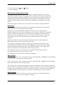
Figure 2-9. The View - Settings dialog
The “Views” checkboxes
The View - Settings dialog box contains two panels of checkboxes bound up in a
“Views” group, with one panel labelled “Current”, and the other panel labelled as
“Other”.
These checkboxes control which graphical overlays are to be displayed in the
various view windows. If the checkbox is checked, that particular overlay or layer is
visible. Deskan v7.1 maintains multiple views of the document in separate
windows on the screen. The window into which the input focus is currently
directed is termed the current view. It is recognized by its highlighted title bar. The
“Current” group of checkboxes control what is displayed in the window which was
current just prior to the dialog box being opened.
For example, if the “Control” checkbox in this group is checked, then the current
view will display control points.
Any other views of the document apart from the current view are controlled by the
checkboxes labelled “Other”. These checkboxes are “tri-state”, and appear initially
greyed and checked in Windows XP. When greyed, the checkboxes have no effect
on the “Other” views; they simply let the views remain in their current state.
The two checkboxes labelled “Layer” determine whether the currently highlighted
layer in the layer selection box is displayed or hidden.
The Active and Target layers cannot be hidden in any view, so if the highlighted
layer is one of these two, you cannot remove the check.
The “Layer” checkbox in the “Current” group controls the visibility of the
highlighted layer in the current view, and similarly, the checkbox in the “Other”
group governs the layer’s appearance in all the other views. As each layer in the list
is highlighted, the contents of these checkboxes can change, as each layer can have a
different combination of these controls, giving the user a certain flexibility in
displaying different layers.
January 2009
Deskan v7.1
2-22
Fundamentals
Layer Selector Box
The layer selection box in the View - Settings dialog is a list of the layer names and
their associated status codes. Selection takes place by highlighting the layer in the
list box then modifying its status. When the dialog box is first opened, the status
icons report the current state of the layer. Any alterations only take effect after the
pressing the “Accept” button.
•
The status icons are displayed in four columns:
The first column indicates the status of the current view
•
means the selected layer is or will become the active layer. It is always
listed first.
•
stands for the Target layer, which is always second on the list.
•
the layer will be opened.
•
the layer will be closed.
The second column uses an “eye” to indicate the visibility of layers in the current
view.
•
Open indicates the layer will be visible in the current view
•
Closed indicates the layer will be hidden in the current view
The third column uses a pair of “eyes” to indicate the visibility of layers in the
other views.
•
the layer will be made visible in all other views
the layer will be hidden in all other views
•
•
no icon indicates that all the other layers will be untouched in
reference to this layer
The fourth column indicator
•
*
the current layer has been modified
•
•
{Layer_Title} The “Layer Title” string following is the name of the layer; it can be
edited using the “Edit Title” button.
Layer control buttons
In the View - Settings dialog is a group of buttons labelled “Selected Layer”. Like
the “Views Current” checkboxes, these controls operate on the layer currently
highlighted in the layer selection box.
The button “Make Active” is used to assign a layer to be a new active layer. It
works for any layer apart from the current active one. Once a layer has been
promoted to active, it rises to the top of the list in the layer selection box, swapping
its place with the former active layer.
The button “Make Target” works in a similar way, assigning any layer other than
the current active layer to be the new Target layer. If the current Target layer is
highlighted, the button reads “Unset Target”, which would then undo the target
assignment. The target layer, if one exists, is always listed second in the layer
selection box.
January 2009
Deskan v7.1
2-23
Fundamentals
The button “Close layer” closes the highlighted layer, releasing it from memory,
and if it had been modified, prompting the user to decide whether to save the
changes or not. Once the layer has been closed, the features in that layer disappear
from all views. The same button will read “Open Layer” if the selected layer is
closed.
When the dialog box is first opened, the checkboxes and status codes report the
current state of the Layers and views. Any alterations only take effect after the
“Accept” button is pressed.
Displaying and Hiding Layers
It is possible to display or hide any combination of layers, by toggling the display
parameter of individual layers. This can be done by checking or unchecking the
Views-Current-Layer checkbox box in the ”View Settings” dialog and clicking the
“Accept” button. For more details on this dialog box ( see ”The View - Settings
dialog.” p 2-21 ). One exception is the current active layer. The layer designated the
current active layer cannot be closed or hidden.
A layer can only be displayed if it is open, (loaded into memory), but an open layer
need not be displayed.
Opening a document causes one particular layer to be opened and displayed as the
current active layer. If the document was opened via it’s RCF, then the last active
layer is used. Otherwise, the status of active layer goes to whichever file was
selected in the file opening dialog.
Any layer other than the current active layer can be closed, releasing it from
memory and optionally writing the data to a disk file.
To hide or close the layer that is the current Active layer, first make another layer
the active layer by highlighting the other layer and clicking on the “Set Active”
button in the View - Settings dialog. You can then hide or close the layer.
If a layer is nominated as the target layer, it is displayed and can not be hidden by
unchecking the “Layer” checkboxes in the View - Settings dialog.
In addition to the Active and Target layers, Deskan v7.1 supports up to 18 other
layers.
All layers apart from the current active layer are initially closed by default when a
document is opened. However, they are available to be opened and displayed on
request by selecting either the Layer - Open - “Open Layers” or the View - Settings
dialogs. They can then be displayed or hidden in any combination.
To hide any of the other layers (apart from the Active and Target), simply open the
View - Settings dialog, select the layer in the list, and uncheck the “Views” “Current” - “Layer” checkbox, then click “Accept”. Any raster elements in the
hidden layer will immediately disappear from view.
Swapping Active-Target
The Layer - Swap menu option simply swaps the current Active and Target layers.
An icon for this command has been provided on both the “Selections” and “Layer”
toolbars.
January 2009
Deskan v7.1
2-24
Fundamentals
Removing Layers
A selection of layers (other than the Active layer) can be removed from a document
using the Layer - Remove menu option.
This also deletes a layer’s raster file from the disk. If you wish to retain any layer as a
separate raster file, you should first export it (see “Exporting a copy of a layer.”, p
2-21).
The current Active layer cannot be removed. First swap it with another layer before
trying to remove it. The current Target layer can be removed. The document will
then have no Target.
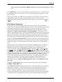
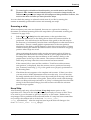
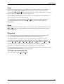
Document Information
A complete profile of a document can be seen in the “Document information”
dialog (see Figure 2-10, p 2-25) by selecting the File - Info... menu option. If
multiple documents are opened, the document in the current view will be the one
examined.
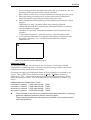
Figure 2-10. The Document Information Dialog
The “Name” display field in the Document Information dialog contains the path
and filename of the document’s Raster Control File.
“Width”, “Height” and “Resolution” show the extents of the raster images in the
document, and their resolution in dots per inch.
There is a list box in the dialog containing five columns with each row describing
one layer within the document. The columns are: “Title” which shows the userdefined name of each layer; “Data File” is the name of the raster file in which the
layer is stored on disk; “Depth” describes the number of bits per pixel and whether
the layer is grey scale; “Format” shows the raster image format; and “Original
Source” which is the name of the raster file, if any, which was imported to form the
layer.
Finally, there are two fields titled “Number of layers” which is the number of
layers in the document and “Memory (bytes)” showing the memory resources
currently consumed by all open layers, in bytes.
If the current document is a Deskan Scan Document, the list box in the dialog
displays some different information pertinent to scanning.
January 2009
Deskan v7.1
2-25
Fundamentals
Figure 2-11. The document information dialog
This is in the form of two columns with the left column identifying the scan setting
title and the right column displaying the value. Only the settings that are relative to
the current document are shown. The settings described are: “Scan Height” which
is a measure of how long the scan is; “Strips Held” is how many strips have been
accepted and kept; “Scanning” described what mode is being used as in
monochrome, grey scale, 8 bit colour or 24 bit colour ; Reduction” is displayed only
if selected; and “Reduce to” identifies how many colours the image will contain.
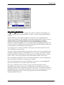
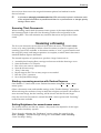
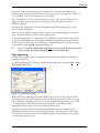
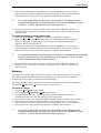
“Configuration” dialog
This dialog box is summoned by selecting the File - Set Up menu option. It is used
for defining the colours of various program components, for opening the QuickKey mappings dialog, modifying default resolution and Context menu delay, and
for selecting monochrome display and logging options.
General Display
The group of buttons labelled “General Display” controls the colour of some
general display elements.
The “Border” button refers to the client area in a view which is not covered by the
actual image, due to a large negative zoom level.
January 2009
Deskan v7.1
2-26
Fundamentals
Figure 2-12. “Configuration” dialog
”Highlight” defines the highlight colour of any selected element, whether they be
graphical overlays such as control points or selected pixel elements.
“Overlays” defines the colour of the graphical overlays such as the fence, control
points and tracking box.
Log operations
Another checkbox, labelled “Log operations”, enables the logging of operations in
the log file.
The log file is an ASCII format file which records informational messages generated
during Deskan v7.1 sessions. This file is called “Deskan50.log” and is formed in the
same directory as the executable file. It records openings and closures of
documents, transformations, and errors, etc.
Logging is always on when in Batch Mode (see “Logging Batch Commands” p 612), and errors are always logged.
Operations are appended to the log file, so it should be periodically cleared of
unwanted information.
Contents of the Deskan v7.1 log file.
The log file records a number of details about the Deskan v7.1 session:
•
•
•
•
•
•
•
•
•
•
Application Start/Stop
Logging Start/Stop
Creation of new blank documents
Creation of new Deskan documents
Layer name changes
Saving a document under a new name (File - Save As)
Raster transformation (File - Transform to) (Residuals output)
Creating a new layer (Layer - New - Blank)
Importing a new layer (Layer - New - Import)
Exporting a layer (Layer - Export)
January 2009
Deskan v7.1
2-27
Fundamentals
•
•
Removing a layers (Layer - Remove)
Error messages.
Monochrome background in black
This toggle defines how a monochrome image is initially displayed if it is being
scanned or loaded from file. This toggle has no influence on monochrome layers in
existing documents. When the toggle is on and a monochrome image is loaded the
background information will be displayed in the darkest colour that exists in the
default document palette and the data will be displayed in the lightest colour that
exists.
When the toggle is off the reverse occurs with the information being the darkest.
Quick keys
The “Key Mappings” button summons the “Quick-key Mappings” dialog which
allows the user to alter the Quick-keys mapping.
Quick-keys are user-defined keys which can be used to access menu options
without using the mouse. They are different to the “hot-keys” which are a standard
feature of Windows applications. The hot-keys are the underscored characters in
menu items. The user must press the “Alt + hot-key” chord in order to access the
main menu item, and after that, the hot-key for each menu item in the menu
sequence.
Quick-keys, however, can reach deeply nested menu items with a single userdefined keystroke, without the need for the Alt key.
The “Quick-key Mappings” dialog contains a list of menu end-options (not the
intermediate menu options). The user can highlight any option and enter a single
unique alphanumeric character in the “Key” field, then click on the “Apply Key”
button to associate the new Quick-key with the menu option.
The “Find Key” button is a convenient way of finding which menu option is
associated with the character in the “Key” field.
The “Default” button resets the default key-mappings.
Special Keys
“F11”. Function key “F11” is equivalent to the command View – Grid File, and will display
a representation of the grid file using Notepad.
“F12”. Function key “F12” is equivalent to the command View – Log File, and will display
the Deskan Express log file using Notepad.
The “Escape” key is a general purpose key whose use depends on the context in which it is
pressed. When a long process is underway and the escape key is pressed, then a dialog will
normally pop up offering the chance to cancel that operation. If however, raster editing is
being performed, then the escape key will remove that editing tool from the cursor.
Save Formats
When the “Save – Format” button is pressed a new dialog is displayed allowing
default formats to be set for each category of image.
January 2009
Deskan v7.1
2-28
Fundamentals
Figure 2-13. Default save formats dialog
These are used to set the format of each layer as it is created. When the layers are
being saved, the associated dialog provides a simple mechanism to change from the
default value if desired. (see “Saving/Closing Documents and Layers” p 2-19).
Sounds
The “Sounds” button opens a dialog from which different varieties of sound
prompts can be selected. These are only used with automatic scanning (see
“Autoscan” p 3-15). The four radio buttons across the top of the dialog allow:
•
No Sound – no sound prompts will be issued
•
PC Speaker – Four distinct sounds will be generated through the PC’s speaker
•
Windows Defaults – The sounds generated will be determined by the settings in
the windows system. The sounds can be configured by selecting “Start Settings – Control Panel” from the start menu, then double clicking on the
sounds icon. The relationship is as follows;
Default – Windows Default Sound,
Control – Windows Asterisk,
Start – Windows Question, and
Error – Windows Exclamation.
•
Custom File – This allows the selection of specific sound files to match the
current event. To establish a file simply press the adjacent “Browse” button.
The adjacent “Test” buttons allows the sound choices to be reviewed.
Figure 2-14. Sound settings dialog
January 2009
Deskan v7.1
2-29
Fundamentals
Default values
There are two input fields in this group.
The “Default Resolution (dpi)” field allows the user to control the default value of
image resolution used for new images and for image formats which do not contain
resolution information in their headers (for example, RLC).
The “Context Menu Delay (Millisec)” allows the user to adjust the approximate
time delay in milliseconds between pressing the right mouse button and the
appearance of the popup “context menu”.
The “Long Process Warning Factor” gives you the ability to back out of potentially
long operations. It works by displaying a warning dialog when a selected activity
is calculated to exceed this factor. From this dialog it is possible to cancel the
command or continue. The actual value has no unit of measurement as it attempts
to account for image size, processor speed and type of operation. Values typically
range from 4 to 10. If the dialog is appearing too often for operations that are
satisfactory increase the value, and if long operations are being starting that you
wish to be warned about reduce the value.
Terminating Deskan v7.1
The File - Exit operation causes Deskan v7.1 to terminate and return to the
operating system.
Any unsaved, modified layers are presented in a dialog so they can be selected for
saving if desired. “Saving” means to update the original raster file with the latest
modifications or saving to disk any new layers. While this dialog is displayed it is
possible to change the format that each layer is saved in by selecting the layer, then
selecting a format from the list at the bottom of the dialog. The list will contain only
those formats that the selected layer can be saved in.
If a document has been bound, then either all of its layers must be saved together or
none at all. This restriction is enforced by the dialogs which appear when Exit is
called while a bound document is loaded.
Printing
The printing capabilities within Deskan v7.1 are controlled from the two menu
options File - Page Setup and File - Print. These two options provide the ability to
scale and place the required output on the output page of any printer or plotter that
has Windows 98, 200 0r XP support. By default a document will be printed at scale
to the default windows printer so printing can be as simple as File - Print and select
OK. If a fence is defined within the document then the required output is taken as
being the fence contents. If no fence exists then the entire document is printed
The File - Page Setup menu option offers a dialog that allows you to control the
document scaling and placement. It can be broadly split in two with the left side
providing the control and measurements and the right side providing a visual
feedback.
January 2009
Deskan v7.1
2-30
Fundamentals
The main
area in the
centre of
the graphic
display
comprises
a dark
colour
inside a
lighter
rectangular
area. This
lighter area
represents
Figure 2-15. The page setup dialog using paper units
the
printable area of the page and is in proportion to the size reported from the printer
driver. The darker colour inside this represents the area that will be printed (the
document output for each page). The size and position of this will change as the
controls are changed. Any dark areas appearing below or to the right of the white
page extents, indicates that the image exceeds the current page size, and that more
than one page is needed to print the document. If the additional rectangle appears
to the right of the central display then the right side of the document overlaps the
page. This is also reported in the dimension group of the controls under Pages
Across. If the additional rectangle is below the central display then the bottom of
the document overlaps the page and this is also reported under Pages Down.
The left side of the dialog provides all the controls and feedback for the setup. The
bottom left group provides feedback as to the physical dimension of the data being
printed. In this group Source refers to the area being printed. This will be either a
fence or the entire document. Output refers to the resulting size on the output
page, and Pages refers to the number and configuration of pages required to
produce the output. The units of measurement for the source and Output can be
selected using the three radio buttons allowing the dimensions to be viewed as
millimetres, centimetres, or inches.
To the right of this group is a button labelled Printer. Selecting it offers a standard
dialog for selecting which printer and page orientation to use. The two buttons
above this will automatically adjust the scaling to accomplish printing at the same
size as scanned (One To One) or at a scale so that all the output will fit on one page
(Fit To Page).
Above the buttons is a small group labelled Justification Initially all the
checkboxes will be blank meaning that the output will be centred on the page. By
checking the checkbox labelled Left the output will be printed on the left side of the
page. Similarly checking the checkbox labelled Top the output will be at the top of
the page. This means that combinations can be used to establish three points of
justification both across and down the page.
The remaining two groups are provided for scale control but they are mutually
exclusive as one uses the image as a reference and the other uses an established
transformation. The required one can be activated by selecting World Units or
Paper Units with a single mouse click.
January 2009
Deskan v7.1
2-31
Fundamentals
When Paper Units is selected the scaling is performed as a simple enlargement /
reduction. Simply select the direction of scaling, then enter the amount. For
example to enlarge the output by two select Enlarge and then enter the value 2 into
the scaling entry box. If you did this you would notice that the values in the output
column of the dimensions group would be double the values in the Source column.
Figure 2-16. The Page Setup dialog using world units
The World Units group is only available when a transformation has been
established (see “ADVANCED TOPICS”, p 6-1 ). If the transformation is available
the output scale can be referenced using a known scale for the source. A good
example of this is when dealing with a scan of a map as in Figure 2-16. This shows
that control has been established and that the original map was at a scale of
1:100,000. The output scale could now be input as 50,000 or 200,000 resulting in an
appropriate doubling or halving of the dimensions as appropriate.
January 2009
Deskan v7.1
2-32
CHAPTER 3
SCANNING WITH DESKAN
Scanning
Chapter 3
Scanning with Deskan Express
This chapter describes the use of Deskan v7.1 for scanning. Initially there is a
description of the components and special document format followed by step by
step procedures for creating documents.
The process of producing an image using Deskan v7.1 is to place the document on
the scanning base and scan the document as a series of strips, starting from the left
and progressing to the right. These strips are then automatically joined by the
software to produce the final image. The scanning is done by a small A4-sized
motorized scanner which has rollers that allow it to move down each strip by itself.
The system of guides controls the scanner as it moves, collecting the scan data.
This means that to scan a document it takes three simple steps:
1. Create a new “scan document” with the required resolution and colour settings;
2. Scan and “Keep” the number of strips necessary to cover the document; then
3. Join the strips to convert the scan document into a normal document containing
the final image as a single layer.
The size of the image being scanned can be controlled in two ways. Using the radio
buttons in the scan settings dialog the length of scanning can be changed between
heights of 300mm(11.75 inches); 600 mm(23.5 inches); or 870 mm(34.25 inches).
Once the first strip has been kept, all additional strips must be scanned at the same
height. The second control is the number of strips to be scanned. This can range
from one up to seven strips for the A0 (U.S. E) size Deskan v7.1 system.
Before we can scan a document the scanning system needs to be set up.
Setting up for Scanning
If you cannot leave the Deskan v7.1 equipment permanently assembled you will
need to go through the following procedure each time you use Deskan v7.1.
Figure 3-1. The components of the Deskan Express hardware
January 2009
Deskan v7.1
3-1
Scanning
Scanning Base
Assemble Deskan Express by first placing the three-piece interlocking backing
panel, called the Scanning Base, on a stable, flat surface free of any irregularities. A
drawing board can be used, but should be adjusted to be level.
The scanning base comes in three separate parts that lock together similar to a
jigsaw puzzle. Position part ‘A’ first on a flat even surface ensuring the guide rail is
furthest from you, place part ‘B’ into the slots of part ‘A’ and finally part ‘C’ into
slots of part ‘B’, all the while ensuring the guide rail on each part is positioned
furthest from you.
You will notice that one side of the Scanning Base has a series of semi-circular slots
in it while the other side has a guide rail. The system is designed to be operated
with the Scanning Base orientated so that the semi-circular slots are closest to you
and the guide rail is furthest from you.
Fix a drawing onto the Scanning Base with adhesive tape, but preferably use thin
clear tape rather than masking tape, as that reduces the possibility of gaps between
the document and the Scanning Guide.
Make sure that the Control Crosses near the top and bottom of the drawing are not
covered as they need to be seen by the scanner so that the software can align the
strips for joining. You will be able to ascertain this better after you fit the Scanning
Guide.
If the drawing is transparent, place a plain white sheet beneath it, to stop the
Control Crosses on the scanning base for the smaller sizes from showing
through.
Scanning Guide
Place the wheels of the Scanning Guide onto the guide rail and slide it to the left
most strip to be scanned. Locate the semi-circular lug on the Scanning Guide into
the semi-circular slot on the Scanning Base.
The Scanning Guide is best positioned by first lifting the end closest to you with the
handle by about ten centimeters and then sliding along the guide rail to the desired
location.
This guide acts as the rail along which the scanner runs.
Control Crosses
Ensure that four Control Crosses on the Scanning Base are visible through the
corners of the transparent window of the Scanning Guide.
Notice that the Scanning Guide has a series of markers running down both sides of
the transparent window. These marks are called Ticks or Tick Marks, and they
provide a calibration system for the scanning process.
Carriage assembly
Note: Prior to using the scanner for the first time and before attaching the scanner
to the carriage, make sure the scanner has been calibrated in it’s calibration cradle.
January 2009
Deskan v7.1
3-2
Scanning
The scanner is supplied with the scanner catch attached to the scanner. You will
find it on the underside of the scanner. The scanner catch bolts to the main housing
of the scanner with 2 x M3 pan head bolts. Screw the two small fixing bolts into the
threaded holes in the scanner base. Tighten the bolts so they are finger tight. The
scanner will need to be aligned parallel with the ticks on the glass panel before the
bolts are fully tightened.
Turn the scanner back to the upright position and attach the scanner catch to the
carriage by sliding the L-pin through the holes, from the rear. Once attached, align
the long edge of the scanner so it is parallel to the ticks. Gently remove scanner
from carriage again and tighten the bolts firmly. Reconnect the scanner to the
carriage.Lift the Scanner off the glass and slide it to the bottom end of the Scanning
Guide.
Figure 3-2. Attaching the scanner catch to the scanner
To check that the assembly is correct refer to the first paragraph of “Scanner
Positioning”.
When the scanner is sitting flat on the Scanning Base ensure the L-pin is
perpendicular to the Scanning Base so that it does not catch on the right hand
Scanning Guide.
Scanner Positioning
When positioning the scanner on the guide there are one of four positions available,
identified by small holes in the right hand side of the guide. The bottom position on
the guide is the end closest to the handle. When standing at the bottom of the guide
the “DESKAN” stencil is visible on the front of the scanner and the scanner cable is
at the left rear of the scanner and the autoscan button is at the top right side.
All of the scanner positions correspond to the various paper heights indicated by
the “flags” on the left hand edge of the Scanning Base.
When the application is opened each time, the scanner will warm up and then the
first strip is always scanned with the scanner placed at the bottom position in the
guide. Depending on the scanning height selected, the scanner will move up the
January 2009
Deskan v7.1
3-3
Scanning
guide to one of the other three positions on the first strip, then from there back to
the bottom on the second strip, and so on.
Except for the bottom position, the scanner should always be positioned so that it sits
behind the small indicator holes in the right hand side of the scanning guide.
If the scanner is not positioned correctly, the resulting scan may not be able to detect
the correct starting position, or a scanned strip may not be able to be kept.
Using the scanner in Deskan v7.1
Deskan v7.1 has been designed to minimize the need to handle the scanner during the
scanning of a document. Typically, the scanner is placed at the bottom of the Scanning
Guide on the left strip to start; and for each subsequent strip the guide is simply moved
right one strip, taking the scanner with it. Each time a strip is to be scanned, a dialog will
display a description of where the scanner is to be positioned. This is also accompanied by a
graphic representation of the correct starting position. When the scanner is in the correct
starting position either press the “OK” button or press the black button on the top of the
scanner.
Figure 3-3. Scanner positioning dialog
Scan Documents
Throughout this chapter, reference is made to a “Scan Document”. This is a special
Deskan Express document (RCF & associated files) which is used to track the
process of scanning and joining. A Scan Document is a Deskan Express document
which is specially marked as being used for scanning in progress.
The scanning options are accessed in Deskan v7.1 through the Scan menu option, or
the Scan toolbar. These options only become available if a Scan Document is loaded.
To initiate a scanning session, create a new Deskan document by selecting the
File - New - Scan menu option. You will be presented with a file-save-as type
dialog box in which you can name of the new document.
The Deskan Settings Dialog is then displayed to determine the type of scanning to
be performed. The settings in this dialog can be changed at any time up until the
first strip is kept.
The reason for having special Scan Documents is to allow you to spread the task of
scanning a large drawing over a number of sessions, without losing previously
scanned strips, and to allow Deskan v7.1 to maintain control over the sequence of
strips required to acquire the full image.
January 2009
Deskan v7.1
3-4
Scanning
While a Scan Document is loaded, certain functions which may interfere with the
scanning process are made unavailable. These functions include file saving and
transformations. Other functions, such as raster editing are still available.
The Deskan Settings Dialog
The Deskan Settings dialog box offers you the chance to adjust any initial settings.
The settings in this dialog can be adjusted up until the first strip is kept after which
only the Brightness (for monochrome scans only) remains available.
Figure 3-4 Initial Settings Dialog
This dialog enables the selection of the type and resolution of the document to be
produced. The “mode” control can be set for Black + White, Grey scale, 8 bit
colour, or 24 bit colour. The “resolution” can be set to various values ranging from
75 dpi up to 600 dpi.
The “Colour Reduction” group of controls is only available if the document is
being scanned using the 8 bit colour mode. With this mode, the scan is captured as
24 bit colour and is then reduced to 8 bit during the keep process. The main benefit
of selecting this option is the 66% reduction in data volume. For a 200 dpi A0
document the size is reduced from approximately 190 Mb down to 64Mb and its
effect on performance is obvious.
Please refer to the following section for more details about 8-bit colour scanning.
The “Apply Colour Correction” checkbox when selected will apply small
corrections to rectify minor variations introduced by the scanning process. In most
cases this is not necessary, and when used it will slow down the keep process.
The “Scan Length” provides three options which determine the length of scanning
performed. When scanning a document, it is always placed in the bottom left
corner of the Scanning Base. If the document fits so that the horizontal line of
Control Crosses adjacent to the 300mm (11.75 inches) mark are still visible, then
select 300mm. If these are covered but the Control Crosses across from the 600mm
mark are visible then select 600mm. If the Control Crosses adjacent to the 870mm
mark are also covered, then the document must be rotated or folded in order to be
scanned.
If the document is too large to fit on the Scanning Base within the Control Crosses,
and needs to be folded and scanned as separate documents, then they can be joined
January 2009
Deskan v7.1
3-5
Scanning
after scanning using the File – Merge command (see “Document Merging” p 6-10 616).
The “Brightness” control is only available for monochrome scans. It ranges from 1
to 100 and is used to control the level of data being acquired (the higher the value
the more data).
Once accepted with the “OK” button the dialog is closed and a scan document is
open but has no data. The Scan Settings dialog can be reopened to make
adjustments and view the current status of the document. It is accessed via Scan Settings.
8 bit Colour Scanning
To produce an 8 bit colour image, the scanner first scans the strip in full 24 bit
colour, then automatically reduces the strip to 8 bits. Colour reduction processing is
performed in two places. When the first strip is about to be kept, the colour
reduction may derive new entries for the document palette suitable for the first
strip ( see “Use the document Palette” in next paragraph). This palette is also
used for all subsequent strips. The second additional processing occurs during the
saving of each strip by converting the data as it is saved. Due to the importance of
the palette contents and order, the menu options that allow modification to the
document palette will be disabled during the remainder of the scanning operation.
When the “Use the document Palette” checkbox is enabled, the Document Palette
will be used for colour reduction, otherwise the program will automatically derive
a suitable number of entries from the first strip as a preparation to keeping that
strip.
The derivation of the colour palette can be a time consuming process if the data
being used has a high resolution or large format size. It can also prove to be
unnecessary if there are a large number of similar images to be scanned. To
overcome this the “Use the document Palette” checkbox, Scan - Derive Palette,
and Colour - Save as Default Palette or Colour - Load Document Palette” menu
options can be combined so that this derivation is performed once only and without
unnecessary processing. The concept is to derive the palette separately using a low
resolution sample strip of the original document that contains all the required
colours, then scan the document at full resolution. The palette derived from the
sample scan can then be saved as the default palette or loaded from the first
scanned document for each subsequent scanning session. For a step by step
description refer to “Tutorial 4: Monochrome Scanning” and “Tutorial 5: Colour
Scanning”.
The Scan - Derive Palette menu option will automatically check the “Use the
document Palette” checkbox.
The “number of colours” option can be used to control the number of colours that
the image is reduced to. The maximum is 256 for an 8 bit image however this
number can be reduced down to any number of colours between 64 and 256
colours. When the number of colours is reduced below 256 then the derived
colours are placed into the document palette from the first entry up to the number
of required colours. The remaining entries in the document palette will contain
January 2009
Deskan v7.1
3-6
Scanning
those colours that were in the original document palette but furthest from the
derived colours.
It is however strongly recommended that 256 colours be kept as it retains as much
of the original information as possible and there is no performance or storage gain by
having a lower value.
Scanning Thick Documents
When scanning small, thick documents insert spacers of the same thickness under
the Scanning Guide so that all of the Scanning Guide is flat and parallel to the
Scanning Base. This will minimize any random distortions and provide a better
result.
Scanning a Drawing
The five scan functions can be selected from either the menu , the Scan Toolbar
icons, or by using Quick Keys. When a Scan Document is created or opened, the
scanning options are available. A document remains a “scan”-type document until
the strips are joined, and image acquisition is complete, at which time it becomes a
standard Deskan Express document.
The normal sequence of operations to produce a large format scan is:
1.
2.
3.
4.
5.
6.
7.
8.
Assemble the Scanning Base, carriage and scanner with the drawing to scan.
Start the Deskan v7.1 software.
Run a few test scans to adjust settings.
Scan the left-most strip.
“Keep” that strip.
Repeat steps 4 and 5 for as many strips as are needed.
Run the “Join” operation.
Save the joined sheet image.
Starting a scanning session with Deskan Express
Start Deskan v7.1 and create a new Deskan document using File - New - Scan
menu option.
Select a document name and suitable settings in the “Deskan Settings” dialog box.
When selecting the resolution, keep in mind that a higher resolution will result in a
more accurate image, but the scanning will be slower and the file size larger.
Once the new Scan Document is created the Scan - menu options and “Scanning”
toolbar become available.
Setting Brightness for monochrome scans
The scanner sensors are like any camera - they need to be adjusted to fit the lightlevels under which they operate.
This is done by adjusting the “Brightness” setting, using the controls in the
Scan - Settings - “Deskan Settings” dialog box or the Scan – Scan Test Strip –
“Scan Test Strip” dialog.
January 2009
Deskan v7.1
3-7
Scanning
In the case of monochrome images, the input to the scanner is the shade of grey
from the image, while the output are the pixel levels, which can only have values of
0 or 1 (Deskan v7.1 always treats the 0’s as the data).
The “Brightness” is set to control the capture of data. Any grey level below this
Brightness grey level gives rise to data pixels, and anything above results in
background pixels.
Increasing the “Brightness” raises the Brightness grey level making more of the
pixels become data pixels.
Once set satisfactorily for white paper it usually only needs changing for coloured
paper, or prints that have a dark or dirty background.
A good starting point is 47 “Brightness” (about midway as the valid range is from 1
to 100). On subsequent uses, the settings established at installation will be used as
initial settings and will only need varying to suit different types of original, such as
coloured lines, dark dyeline print background, etc.
Note: The scanning Brightness level must be set at a level where the ticks and
control crosses are clearly distingiuished from the background.
Test scanning
Deskan Express allows you to experiment with different “Brightness” settings by
scanning test scans.
To test the Brightness, position the scanner on the guide, then select the Scan - Scan
Test Strip menu option.
Figure 3-5. Scanning Test Strips
When the dialog is displayed, set the length of the test scan by choosing the units,
then entering a length. The Brightness can be adjusted, if necessary, and a test scan
can be started by pressing “Scan Up” to scan the required length back up the guide,
or “Scan Down” to scan that distance down the guide. Any change to the
Brightness will be retained for the scanning of whole strips.
For grey level and colour scans unsatisfactory results can only be improved by
changing the resolution or re-calibrating the scanner. You may need to repeat the
test scans several times to arrive at suitable settings for a document of poor quality,
or until experience is gained.
January 2009
Deskan v7.1
3-8
Scanning
For scanning the old white-on-blue blueprints, you would need to use Deskan
Express’s File - Invert command subsequently to reverse the image tonality, as
Deskan would generate an image with the background being the data. However, this
must not be done until after you have joined the strips.
You can check the settings on selected critical areas if you like by starting the
scanner at manually positioned locations and scanning test strips.
Scanning a strip
When satisfactory test scans are obtained, there are two options for scanning a
document. For manual scanning follow the steps below (for automatic scanning see
“Autoscan”on page 3-15):
1.
2.
Select Scan - Scan Strip from the main menu or the equivalent icon ,
Follow the instructions on the dialog about where the scanner needs to be
positioned. This will always be the bottom of the guide on the left strip for
the first scan of a document, but after that it will depend on what actions have
been taken. There is a small graphic representation of the start position
displayed on the dialog, which changes to show the correct position. During
normal scanning the scanner should not need to be moved from its stopping
position when strips are saved.
After positioning the scanner make sure the movement path is all clear so
the cables will afford free movement, and the L-pin is perpendicular to the
Scanning Base, then press the start button on the scanner’s dialog or the
purple button on the top of the scanner. The scanner will then scan the
entire strip and stop when the correct amount has been scanned.
If the scanner fails to start and the condition “Could not confirm scanner
start position” is displayed, then the scanner was not positioned correctly
(see “Scanner Positioning” p 3-3), or the guide is not properly positioned on
the Scanning Base.
3.
Check that the strip appears to be complete and accurate. If data is too faint
you may wish to make adjustments and re-scan the strip. You will see that
the image includes the Control Crosses above and below the strip, and all the
tick marks down both sides of the guide. These will be saved with the image
when you Keep each strip (referred to as “Keep” to distinguish from the final
saving of the whole sheet image), but will be removed when the software
joins the strips together.
Keep Strip
After scanning each strip, select the Scan - Keep Strip menu option or the
equivalent icon. This saves the image of the strip currently on screen to disk. There
is no need to give a file name or specify a directory or file format. Deskan saves
strip images with a predefined file name and format. If a strip has been scanned but
not yet kept, the window title is of the form: “document_name:
Strip_#(unchecked)”. After the strip has been kept the title will change to the
form: “document_name: Strip_#(kept)”
January 2009
Deskan v7.1
3-9
Scanning
If you look in the working directory, you will notice a .rcf file with the name you
nominated at the beginning, plus other files with extensions .$cx and .$px where x is
a number or a letter. Each kept strip results in a .$cx and .$px file pair.
Additional processing may occur for colour reduction, colour correction, and edge
adjustments. This is reported on the status bar.
It is not necessary to scan all strips in the one Deskan v7.1 session. As the strip
image files and status information are saved on the disk, scanning the whole
drawing can be spread over several Deskan v7.1 sessions if necessary. Simply keep
the last strip scanned as described above, and exit Deskan Express.
If an error occurs refer to “Keep Errors” on page 3-11 for an explanation on the
possible reasons.
Positioning the Scanning Guide for the next strip
Once a strip has been “Kept”, the scanning guide should be lifted by the handle so
that the glass is clear of the document, and then slid to the right along the rail at the
top of the guide. When the guide is directly over the next strip, lower the handle so
that the alignment key drops into the cut-out in the scanning base.
Ensure that the control crosses under the top end of the scanning guide are
approximately centred between the ticks on the guide, as shown in the diagram
below, before lowering the guide handle. If not, you will need to lift the handle to
adjust the positioning at the top end.
Figure 3-6. Control Crosses centred between Ticks on Guide.
Note: If the guide is not correctly positioned, the quality of the joined image may be
affected.
Join Strips
Once all the required strips have been scanned and kept, the join operation is used
to retrieve each strip image in sequence, and join it to the previous strip in memory.
Joining is initiated by selecting the Scan - Join menu option.
The tick marks on the guide are used to sense whether there has been any
stretching or squeezing of the strip image vertically. It spreads or compresses the
image between each set of marks to make the marks appear exactly at the correct
spacing, and then fits the strip into its correct location, removing the calibration
marks as it does so.
January 2009
Deskan v7.1
3-10
Scanning
The Join operation may take considerable time for large, high resolution drawings,
as the software does much checking and geometrical correction to guarantee overall
accuracy.
For very large scanning jobs, it may be preferable to allow the join to be performed
while the PC is unattended (see “Join” p 6-13).
Save Joined Image
Once the Join operation finishes , a Save Layers dialog is presented.
Adjust the output raster format if necessary then simply click on the Save button,
and all the data is saved into a single raster image file with the proper file format
extension. All the intermediate .$cx and .$px files are erased, and the document
becomes a normal Deskan Express document.
The image still in memory can be processed by Deskan v7.1 without having to
reload it from the file. In fact, you could use any of Deskan Express’s raster editing
before saving but it is wise to save it first.
Effective Y Resolution
It has been determined that when scanning in grey-scale or colour at higher
resolutions, some computers do not have sufficient performance to obtain the
selected resolution in the vertical direction. Despite this, the methods employed in
merging the strips will still produce an accurate image, and in most cases no
difference can been seen.
The problem can be identified by measuring the distance between the horizontal
tick lines up either side of the scanned strip. Under normal circumstances this
would measure at approximately 10mm, but when the performance is deteriorated
may drop as low as 6 or 7 mm.
In some cases this problem can cause the scanning of a strip to fail. When this
occurs, displaying the control markers (select View-Control) will reveal a
consecutive pair of markers that do not fall on a horizontal tick line, possibly
followed by a tick line without a marker. This is caused by the tick separation
being excessively smaller that its correct value.
To correct the problem recalculate the scanning margins using the command Scan Utilities - Autoscan Margins. This command will automatically recalculate the
effective Y resolution at all nominal resolutions.
This problem arises when the automatic setting of the scan margins and the
scanning of a strip, are performed with the computer running under significantly
different loads.
Keep Errors
Occasionally the Keep operation may display an error message saying that the strip
cannot be saved. There are three reasons why this might happen:
1.
2.
3.
The system could not locate the cross at all “Errors 1 to 3),
The system could not locate the cross accurately enough (Errors 4 to 9), or:
The strip was too distorted to be accurately adjusted (Errors 10 to 12).
January 2009
Deskan v7.1
3-11
Scanning
In the first two cases, the view of the image will have been centred on the problem
area, and a highlighted box will show where the control information was expected
to be found. In addition the display of the control marks is switched on showing
the locations of the crosses which were found. The crosses are looked for in the
order:
1. Tick marks from bottom to top on the left side,
2. Tick marks from bottom to top on the right side,
3. Top left Control Cross,
4. Top right Control Cross,
5. Bottom left Control Cross, and
6. Bottom right Control Cross.
Control Location Variables
On executing the Scan - Keep command the program's first task is to locate the two
vertical lines that form the tick marks. This process relies on two stored
measurements, which are dependent on the particular scanner being used.
When either of these is incorrect the keep operation may fail with the error message
"Could not identify vertical tick lines".
To rectify the problem use the command Scan - Utilities - Autoscan Margins to
recalculate these two measurements as well as the scanning margins.
Whenever the scanner head is changed the command Scan - Utilities - Autoscan
Margins should be used.
Line Quality
Before detailing each error message we must first understand the term line quality
as it is used in describing many of the errors. The Control Crosses and tick marks
are all fundamentally black on a white background, and each is made up of four
arms that are right angles to each other. When they are scanned using different
modes and resolutions the quality of those lines can vary. The edges can become
jagged, and different circumstances can cause light areas to appear within the lines.
It is also possible that the detection may become confused with stray marks on the
paper. These are the factors which affect the line quality and are often referred to
in this manual as distortions. When the errors occur it is often possible to fix them
by using the editing tools to remove the stray marks, to darken light areas within
the lines or straighten out the edges. This must however be done with caution, as it
has a direct effect on the accuracy of the final image.
The following paragraphs list the possible errors and describe possible causes and
remedies.
Error 1. "Could not find a cross in the expected area"
This error indicates that nothing resembling a cross could be found in the image at the
expected location. The view in the window will show the rectangle at the expected position.
January 2009
Deskan v7.1
3-12
Scanning
If the expected position is along the vertical line connecting the tick marks then there are two
main causes:
1. The scanner was impeded causing extra scan lines to be acquired between the last
tick mark found and the highlighted location. This can be tested for by
measuring the distance from the last found tick mark and the middle of the
expected location. This distance should be approximately 10mm, and a measure
over 11mm indicates this as the problem. The solution is to identify what
impeded the scanner and ensure it does not happen again, then rescan the strip.
Typical causes are having the cable dragging across the edge of the table, or
having too many applications running on the computer.
2. The scanner stopped then restarted while directly over the tick. This causes the
scanner to rock slightly, and is sometimes sufficient to hide the tick mark
altogether. This can be identified by the expected location being half way
between two ticks, which are approximately 20mm apart. The solution is the
same as described in the previous paragraph.
If the expected position is towards the centre of the image from the tick marks, then
one of the four Control Crosses could not be found. Again there are two main
causes:
1.
2.
If the expected location is a multiple of 10mm above or below where the Control
Cross exists, then the problem is actually with the tick marks. Go to the bottom of
the image on the side where the error occurred, and check that the tick marks at the
bottom were detected. If they weren’t found then check the quality of the lines for
evenness and darkness. If they were found then it is possible that one of the tick
marks along the edge was missed. Scroll up the image checking that every tick mark
has a corresponding marker displayed.
If the expected position is adjacent to the Control Cross but to the left or right of it,
then the Scanning Guide was not properly positioned on the Scanning Base. Correct
the problem and rescan the strip.
Error 2. "Could not find a horizontal line"
This error indicates that no horizontal line could be detected near the bottom of the image.
This is normally caused by having too high a Brightness when scanning a Black + White
image. The problem is that the horizontal tick lines become obscured by the background
noise causing the scanner to stop short, leaving the bottom of the scan with just a fill pattern.
To fix the problem perform test scans reducing the Brightness until the tick marks are clean.
Another possibility is that the scanner was manually positioned at a start mark lower then
the set length. For example, if the scanner was placed at the 300mm mark when the scan
length is set at 600mm, this error would occur. This results in the scanner being obstructed
at the bottom of the guide, but still scanning until the image is filled. Simply scan the strip
again, as this time it will scan from the bottom up and obtain the correct data.
Error 3. "Could not find a vertical line"
This error indicates that no vertical line could be detected near the bottom of the image.
This is normally caused by the quality of the line being insufficient for detection. Either
darken the vertical line or rescan the strip
January 2009
Deskan v7.1
3-13
Scanning
Error 4.
Error 5.
Error 6.
Error 7.
Error 8.
Error 9.
"Top arm of the cross is distorted"
"Bottom arm of the cross is distorted"
"Left arm of the cross is distorted"
"Right arm of the cross is distorted"
"Combined top and bottom arms of the cross are distorted"
"Combined left and right arms of the cross are distorted"
Errors 4 through 9 all deal with the poor line quality (see “Line Quality” p 3-12). The top,
right, bottom, and left identify which arm of the cross is in question. In some cases the
opposite arms of a cross are combined and used as a single line. When this is done errors 8
and 9 may occur. In this case it is the quality of both the opposing arms that must be
considered.
Error 10. … left side was impeded
This error indicates that the left hand side of the scanner was physically restrained
or failed to progress during the scan. It can be detected in the image by the tick
marks being more than 10mm apart. This is because the scanner actually captures
more scan lines than normal over the same distance.
Check that the scanning path is not obstructed and that the scanner tracks in a
constant, straight path along the guide. Ensure that the cable does not cause any
restraints also. Another cure is to clean the wheels of the scanner by removing any
accumulated dust.
It is up to personal preference as to whether the error should be ignored, or the strip
rescanned. If ignored the final image will be distorted in this area.
Error 11. … right side was impeded …
This is a similar problem to Error 10, but it has occurred on the right hand side. The same
analysis and options are valid.
Error 12. … Scanning width deviated …
As the Scanning Guide is on top of the document being scanned, adjustments must be made
to cater for the varying thickness of documents. It is however assumed that the thickness of
the document is consistent. This error indicates that this is not the case. A typical cause is to
be scanning a document which has a suspension strip attached to one end. This makes one
end of the document thicker than the other. The solution is to obtain a piece of thin
cardboard or film that can be placed under the document (not under the suspension strip).
When this is done the Control Crosses at the top and bottom must still be visible. The result
is that the top of the document is held against the guide and the document thickness is
consistent.
Discard strips
The Scan - Discard Strip option discards all saved strips and is equivalent to
having just created the Scan Document.
Resuming a scanning session
On resuming Deskan Express, use File - Open to load the Raster Control File for the
Deskan document. Deskan v7.1 recognizes a Scan Document and will automatically
allow further strips to be scanned. Deskan documents are distinguished by their
January 2009
Deskan v7.1
3-14
Scanning
view windows having a title of the form: “document_name: (no data)” as opposed
to the normal Deskan v7.1 convention of “document_name: layer_name”.
It is important to ensure that the strips are scanned in sequence left to right, and
that no strip is missed or duplicated.
The Scan - Settings - “Deskan settings” dialog shows the number of strips already
scanned and kept.
Autoscan
An alternative to scanning each strip individually is to use the Autoscan command.
This starts a scan in the same way as simply scanning a strip, but when the strip is
obtained, it is automatically kept. When the keep succeeds you are automatically
prompted to scan the next strip. This process repeats until all the required strips
are kept, at which time simply press the escape key or select the cancel button.
In addition Autoscan will also provide audible cues (see “Sounds” p 2-29) for each
prompt.
This means that to scan a document, you select the Scan – Auto Scan command,
move to the scanner and position it, and press the purple button on the scanner.
From there continue to act on the cues to move the guide and scanner to the next
strip, starting the scan using the purple button on the scanner. There is no need to
return to the computer until the scanning is finished.
If a problem does arise, the process will stop until resolved. After this Autoscan
can be restarted, to continue automatic scanning.
Adjustments
There are several forms of adjustments that can be performed in relation to scanning. To
check if adjustments are necessary refer to the following check list:
1. Perform a test scan in Black + White at 100 dpi. Measure the distance between the left
edge of the image and the left vertical line containing the tick marks; and the distance
between the right edge and the right vertical line containing the tick marks. If either of
these is less than 3mm then perform an “automatic margin adjustment”.
2. Perform the same test as for (1) but using some other mode and resolution. If test (1) is
good, but this test fails, then perform “Setting the scanning Margins”.
3. Perform a test scan in the required mode and resolution.
If the scan is light on one side and dark on the other perform a “Scanner Calibration”.
If there are vertical bands of colour down the image perform a “Scanner Calibration”
(When this happens it is sometimes necessary to delete the file “HS600.clb” before recalibrating).
If there are thin vertical lines in the scan clean the lens of the scanner with a soft cloth.
Do not use abrasives or harsh chemicals.
4. If a document has been scanned, but the quality of the joins is poor, the cause could be
one of the following.
If the document is thick or uneven in thickness perform “Monument Width
Calibration” for each strip being used.
If the document is thin the problem is in computer performance, in that the data was
interrupted during transfer from the scanner to the program. If other applications were
January 2009
Deskan v7.1
3-15
Scanning
running, then close them. If the problem persists, then it may be necessary to
defragment the hard drive, or add more memory.
Setting the scanning margins
The command Scan – Utilities – Set Margins allows the scanning margins for the
current mode and resolution to be set. These margins control how much
information from the sides of the scans are removed during the scanning process. If
too much is removed errors will occur when trying to keep the strip. If too little is
removed then background information may confuse the cross location mechanisms.
For best results the margins should be set so that 3 – 5 mm of image data is
available outside of the vertical lines connecting the tick marks.
Figure 3-7. Setting the scanning margins manually.
To set the margins, use the scan settings dialog to set the mode and resolution
required, and ensure that the scanner is positioned on the guide at least 2cm down
from the top. When the command Scan – Utilities – Set Margins is selected the
scanner will automatically scan a 2cm strip showing the full width of the scan. On
the left and right sides of the image will be two vertical lines. The top line shows
the current setting and the bottom line represents the new setting. A dialog is also
displayed for manipulating these margins.
By selecting “Left margin” or “Right Margin” the display is scrolled between the
left and right sides. Each press of the “<< move” and “move >>” buttons will move
the lower margin being displayed to the left or right.
Once the bottom lines on both sides are in appropriate positions select the “OK”
button to save the new margins.
Autoscan Margins
In rare circumstances it may be necessary to readjust the margins for every possible
mode and resolution, as Deskan v7.1 version 5.0 supports 20 combinations of mode
and resolution which require margins, the process of setting the margins can be
both tedious and time consuming.
To alleviate this problem the command Scan – Utilities – Autoscan Margins has
been provided. This command will adjust the 20 margin pairs automatically.
When the command is selected the following dialog appears giving instructions on
how to set up the scanner.
January 2009
Deskan v7.1
3-16
Scanning
Figure 3-8. Adjusting scanner margins automatically
When the “Yes” button is pressed a dialog is displayed which indicates the
progress. The scanner will move up to an area between the Control Crosses and
start performing a series of short scans. Each scan will be at a different mode and
resolution, and from each appropriate margins will be determined.
When all have been done a confirmation dialog is displayed.
Scanner Calibration
When the colours do not appear correct, or there is a variation in the lightness
between the left and right side of a strip, then the scanner head requires recalibration.
Select Scan – Calibrate and the following dialog will be shown.
DESKAN 6
Place scanner in calibration cradle
and press OK.
Figure 3-9. Scanner calibration
Place the scanner on the calibration cradle (shown below). The “OK” button will
become enabled. Select “OK” to start the calibration process, which will take
approximately one minute.
Note: The scanner will go through the 45 second warm up sequence before
calibrating.
It may be necessary to re-calibrate the scanner when there is a significant change in
the ambient lighting conditions in which the scanner is operating.
January 2009
Deskan v7.1
3-17
Scanning
Monument Width Calibration
Introduction
Within Deskan Express the distance between pairs of Control Crosses is measured
so that adjustments can be made to correct for changes in document thickness. A
default “Monument (Control Cross) Width Calibration” is performed prior to
delivery and it is suitable for most scanning sessions. Performing additional
monument width calibrations can produce better results when scanning thick
documents, documents of varying thickness, or documents that are not completely
flat.
The current monument width settings are contained in the Deskan Express ‘grid’ or
‘calibration’ file. The contents of the grid file can be viewed by selecting the menu
option View – Grid File, or pressing function key “F11”.
Example contents of a grid calibration file:
“D: \JOBS\DESKAN\Calib.grd”
File Format version: 1.1
File Serial number: A0970601
Measured Monument widths
| 7.0932 || 0.0000 || 0.0000
| 7.0927 || 0.0000 || 0.0000
| 7.0918 || 0.0000 || 0.0000
| 7.0950 || 0.0000 || 0.0000
||
||
||
||
0.0000 ||
0.0000 ||
0.0000 ||
0.0000 ||
0.0000 ||
0.0000 ||
0.0000 ||
0.0000 ||
0.0000 ||
0.0000 ||
0.0000 ||
0.0000 ||
0.0000 |
0.0000 |
0.0000 |
0.0000 |
The above example shows a typical default calibration, with each column showing
the monument widths for each strip. Widths of 0.0000 indicate that the
measurements from the previous strip are to be used. The procedure in the
following section (Calibrating the Monument Widths for a Strip) can be used to add
calibration information to any strip, and the section labelled “Removing Monument
Widths” on page 3-19 enables calibration information to be removed.
Calibrating the Monument Widths for a Strip
1. Prepare the scanner hardware by removing all documents so that the
Scanning Guide is sitting flat on the Scanning Base on the strip to be
calibrated. The scanner is to be positioned at the bottom of the guide.
2. Start Deskan Express and create a new scan document. The name is not
important as this document will not be kept, but the scan document must
be created as Black + White mode with a resolution of 600 dpi and select a
Brightness that produces a clear image of the control points. The scan
length must also be set at 870mm.
3. From the menu select Scan – Utilities – Autoscan Monument Widths.
4. Answer “Yes” to the dialog requesting confirmation to perform
“Recalibrate monument widths”.
5. In the dialog titled “Enter Strip Number 1..7” enter the strip number to be
calibrated. Remember that they are numbered from 1 on the left, up to
either 4 or 7 on the right.
6. The next dialog requests confirmation to “Continue on Deviation Errors”.
This refers to the errors that occur during a keep, where the scanner has
been detected as having been impeded. If you answer “Yes” and this
January 2009
Deskan v7.1
3-18
Scanning
occurs, the strip will be discarded and rescanned. If you answer “No” the
problem will be reported and the process cancelled.
Errors where crosses are not located will always cause the process to stop.
7. When the dialog prompting you to position the scanner is displayed,
check the scanner is properly positioned, then press “OK”.
8. Once selected the following dialog will be displayed showing the current
progress.
“Measuring for strip” identifies which strip is being calibrated.
“Minimum scans allowed” indicates the minimum number of scans that
must be done and accepted.
“Number of scans held” indicates the number of scans that have been
accepted.
“Current Maximum error” gets the accuracy of the information held.
9. Once sufficient information is captured a final dialog is displayed with
the results. Selecting “Yes” will add this information to the grid
calibration file.
Figure 3-10. Monument width calibration report.
Important Points
It is possible to calibrate several strips in the one session. Each strip is treated
individually so calibrating strip 2, then moving the Scanning Guide to strip 3 and
calibrating it will produce the correct results.
Providing that logging is enabled the details of each calibration is recorded in the
log file. The log file can be viewed by selecting View – Log File or pressing
function key “F12”. Notice that in the example provided the new average values
match the measured values. This is because it is the first calibration (“Scan 1”) of
Strip 2.
Update Monument Widths Strip 2, Scan 1
monument 0 measure 7.0941 new average
monument 1 measure 7.0906 new average
monument 2 measure 7.0912 new average
monument 3 measure 7.0938 new average
7.0941
7.0906
7.0912
7.0938
The information in this section is provided to assist advanced users in resolving
particular adjustment problems with the scanning system.
These adjustments should not be required to be made in the normal course of
scanning operations.
January 2009
Deskan v7.1
3-19
Scanning
Removing Monument Widths
This command allows for the removal of monument width calibration for strips 2
and higher. Strip 1 cannot be removed as it is required as a default.
On selecting the command Scan – Utilities – Remove Monument Widths you are
prompted to enter the strip number to be removed. From this two reports will be
issued advising that the widths have been successfully removed. If a problem
exists with this command ensure that the file “calib.grd” is not read-only.
Care and Maintenance
Scanning Base – The scanning base is made from acrylic and should only be
washed with mild soap or detergent and water. Dry with a soft cloth.
Some chemicals are extremily damaging to acrylic, in particular DO NOT use
window cleaning sprays, scouring compounds, acetone, petrol, benzine, carbon
tetrachloride or lacquer thinner. Sticky residues can however be removed with
hexane, kerosene or citrus-based cleaner. Solvent residues should be removed by
washing immediately.
Caution should be exercised when cleaning near and around the graphics printed on
the scanning base. No chemicals of any kind should be applied to the printed
graphics otherwise damage to the graphics may result. Likewise harsh rubbing of the
printed graphics may also cause damage.
Scanning Guide (Sides) – The sides of the Scanning Guide are made from anodised
aluminium. Aluminium cleaning agents should have a pH within 5 - 8 and be free
of fluorides, chlorides, or sulphates. Cleaning should be regularly performed using
a soft cloth or fibre brush, warm water and neutral detergent, followed by thorough
rinsing with clean water. Ensure that all residues are removed from crevices.
Stubborn marks may be removed with a nylon brush or abrasive pad. Greasy
deposits may require a soft cloth dipped in white spirits. To clean long neglected
areas it is advisable to use proprietary cleaners specifically formulated for anodised
aluminium surfaces. These products contain residual waxes, etc, and can
substantially improve the appearance of worn or weathered surfaces.
The use of strong acid or alkaline cleaning agents will damage the anodised coating
on aluminium components.
Guide Handle – The guide handle is made from powder coated aluminium.
The powder coated scanner handle should be regularly washed (at least every 6
months) to remove the natural accumulation of dirt and grime. In areas where
airborne salt deposits and atmospheric pollution is high, maintenance should be
more frequent. Wash using mild detergent and soft sponge or cloth. Rinse
thoroughly with clean water to remove residual detergent. Stubborn stains can be
removed with either mineral turpentine or methylated spirits.
January 2009
Deskan v7.1
3-20
Scanning
The use of harsh solvents (eg, lacquer thinners) or abrasive pads will damage the
powder coating’s appearance and performance.
Scanning Guide (glass) – The glass base forms part of the Scanning Guide.
The glass should be cleaned with mild soap or detergent and water. Dry with a soft
lint free cloth.
The glass used in the base is “hardened” glass but can be easily damaged or
smashed if due care is not excercised.
The operator of the Deskan System should note that there are no user servicable
parts in either the scanner head or the associated hardware.
Lubrication is not advised nor required for any of the parts.
January 2009
Deskan v7.1
3-21
Scanning
Getting Assistance
Occasionally, you may need to contact Technical Support to assist you in resolving
problems with Scan, Keep and/or Join operations.
When this occurs, the following guidelines will help you provide Technical Support
with all of the necessary information to permit a quick resolution to the problem.
Technical Support can be contacted via email at:
[email protected]
The following information should be provided with any technical support request:
1. Deskan Express hardware serial number. This number is located on the
scanning guide and base.
2. The hardware lock (dongle) serial number. This is a 5 digit number on the
hardware lock.
3. The exact software version number. Go to Help - About and note the exact
version number (e.g. version 6.0.2.12).
4. The error message, including any error codes reported.
Files to send for technical support
If you are emailing technical support, attach the files:
1. Deskan60.ini – located in your Windows directory (typically “C:\Windows”).
2. Calib.grd – located in the Deskan Express 6 installation directory (typically
“C:\Program Files\Deskan v7.1”).
Additionally, attach the files described below for the specific problems.
Scanning and Keeping Errors
If you have problems with the Scan or Keep processes, select Layer – Export, and
save the data as a standard raster file.
Send the saved raster file so that technical support can repeat the error.
Join Errors
If there are problems with the quality of the stitching in the Join process, please
follow these steps:
1. Start a new scan document in an empty directory,
2. Scan and Keep 2 or 3 strips – do not Join.
3. Exit Deskan Express.
January 2009
Deskan v7.1
3-22
Scanning
4. Attach all files in the directory to an email and sent to technical support.
Preferably, compress the files into a ZIP file.
Colour Balancing
If there is vertical striping or incorrect colours in the image, the Scanner head
requires recalibration (refer to “Scanner Calibration”, p 3-17).
January 2009
Deskan v7.1
3-23
CHAPTER 4
IMAGE EDITING
Image Editing
Chapter 4
IMAGE EDITING
Having obtained an image this chapter deals with manipulating that image. The
topics covered involve the use of editing tools for direct adjustments; simple
transformations to adjust the whole image; and colour manipulations to modify the
appearance. It also covers methods to transfer information between layers enabling
the image to be broken down into parts.
Introduction to Raster Editing
It is often desirable to be able to make alterations to the raster image before printing
in order to improve the final result. Some of these corrections can be quite minor,
for example, erasing unwanted pixels causing spreading or merging of lines due to
smudges in the original scanned drawing.
At other times, raster drawings may need major alterations, such as the deletion of
a large area.
Raster images can be modified by using
•
•
•
•
•
Colour manipulation
Drawing tools,
Fence operations,
Layer separation operations
Simple Transformations
These are discussed individually in the following sections.
Invert
This operation behaves differently depending on the type of layer being inverted. If
the layer is 4 bit or 8 bit colour then the data is left untouched but the palette for
that layer is inverted so that red becomes cyan, blue becomes yellow etc.
Technically what happens is that every intensity definition within the palette is
subtracted from 255. For all other layers the data is modified so that for
monochrome the background and foreground is swapped; with grey scale the
intensities are inverted (every pixel is replaced by 255 minus itself); and for 24 bit
colour each colour component is inverted. It is generally used only once with
monochrome layers to rectify the foreground/background colours of an image to
suit Deskan v7.1’s convention. (see “Colour, Palettes and Transparency”, p 2-15)
An example of this is the scanning of old-style blueprints. These drawings are white
on a blue background, and when scanned result in a “black-on-white” image which
has to be inverted.
An important point to remember with monochrome layers is that they can look
right but still be inverted. The solution to this problem is to check the background
appearance colour in Colours - Base Colour - Select. The layer’s background will
always match this colour.
January 2009
Deskan v7.1
4-1
Image Editing
To invert selected layers:
If the document contains only one layer then selecting File - Invert. Will
automatically invert that layer. If there is more than one layer then perform the
following:
1. Select the menu option File - Invert. In the dialog box which appears, a list of
currently open layers is presented.
2. Select the layers to invert, then click on the “Invert” button.
January 2009
Deskan v7.1
4-2
Image Editing
Colour and Depth Reduction
When the active layer is an 8 or 24 bit image, the menu option Layer – Reduce Colours
becomes available. This command will reduce the number of colours in the active layer.
When the command is selected there is a prompt for the number of colours wanted. If a
number between 8 and 16 (inclusive) is entered, then the resulting image will be a 4 bit
image. If a number between 17 and 256 (inclusive) is entered the result will be an 8 bit
image.
If the active layer is the only layer in the document, then a second prompt will be offered to
allow for the document’s palette to be replaced. If this offer is accepted then a palette will be
derived for the image, and that palette will be merged with the current document palette.
When this occurs, only the selected number of colours are derived and placed in the
document’s palette.
As an example, let us say that 8 colours were selected. The active layer would be reduced to
a 4 bit layer containing only 8 different pixels values. The palette entries describing these
pixel values will be placed in the document palette as the first 8 entries. Of all the original
entries in the document palette, the 8 entries that were the closest match to the new entries
will be discarded.
If the offer to replace the document palette is not accepted, the same 4 bit layer would be
produced, but the colour representation will be the closest found in the existing document
palette.
If the active layer is already an 8 bit layer and the number of colours selected is greater than
the number of colours that exist, then the image will not be changed.
Should the results be unsatisfactory then the command Edit – Reload can be used to reload
the original image.
The Edit – Reload command is only available if the layer exists as a file on disk. As
an example, if a 24 bit image has just been scanned and joined, but not saved, then
the command is unavailable.
The Edit – Reload command does not undo any changes to the document palette.
Colour Manipulation
Colour manipulation refers to both modifications to the palettes and modifications
to the colour references for pixels. As described in “Colour, Palettes and
Transparency”, p 2-15, a document contains at least a document palette with 256
entries and possibly additional palettes of varying sizes for some layers. When
these layer palettes exist every entry within them will have a matching entry within
the document palette.
Editing Layer Palettes
Layer palettes can be directly edited using Colour - Edit Layer Palette. When this
is used, a single click on an entry will select that entry and provide details as to the
colour intensities and palette index for both the layer and document palette.
Double clicking on an entry or pressing the edit button for the selected entry will
offer the document palette so that an alternate entry can be used for pixels
matching that value. This provides a mechanism for altering the appearance of a
layer without having to locate individual pixels to change, but must be used with
care as every pixel within the layer matching that entry will change even if it is not
in view.
January 2009
Deskan v7.1
4-3
Image Editing
Getting Information about pixels
A tool has been provided under the command Colour - Measure Pixels which
makes it possible to interrogate the image to obtain colour information. Once
selected, a single press will provide both the colour and palette information for the
selected pixel. By pressing and holding the left button, then dragging it to define a
rectangular area, it is possible to obtain the average colour values for the area, and
the palette indexes for the colour nearest to the average.
Interactively manipulating the layer palette
This tool is not available for monochrome or 24 bit layers as they have no palette.
There are two tools available that manipulate a layer’s palette in an interactive way.
They can be selected by Colour - Merge Palette Entry to - Drawing Colour and
Colour - Merge Palette Entry to: - Background Colour. Once the tool is selected, a
left button press on a colour in the image will modify the palette definition for that
pixel’s palette entry to match the definition for the currently defined drawing
colour or background colour depending on which tool was selected. The tool also
has the ability to accept multiple pixels by dragging over an area. In this case,
every pixel within the selected area is checked and all associated palette definitions
are modified. For each adjustment made with the left button a press of the right
button will undo that change. This undo feature is only available while the tool is
selected and once the tool is changed any adjustments made become permanent.
The tool remains selected when using controls to scroll and zoom.
Cut and paste operations on pixels modified this way will cause the pixels
themselves to be modified during any subsequent cut/copy and paste operations.
Editing the document palette
The document palette can also be edited in a similar way to layer palettes by using
the command Colour:- Edit Document Palette. There are two differences between
the two dialogs. Firstly, the “Edit Colour” button produces the standard Windows
dialog for defining a colour. Secondly, accepting the changes affects every layer in
the document, including any layers that may be closed.
It is also possible to completely replace the document palette or save it to an
Auxiliary Data File, although these features are normally only used in relation to
scanning images. If a new document palette is loaded into an existing document
then every palletized layer will be modified to suit the new palette.
Another modification available for the document palette is the sort option. This is
accessed via the command Colour - Sort Document Palette and simply sorts the
entries in the palette into ascending order of average intensity. In some cases, this
makes the palette easier to work with but it has no effect on the document other
than the order of display in the dialog.
Scanning and Palettes
When a document is scanned, each colour on the original document is normally
captured as several shades of that colour. This is due to both noise and lighting
variations picked up by the scanning system. This becomes particularly important
January 2009
Deskan v7.1
4-4
Image Editing
for Black + White as these colours most often represent the background. In order to
correct this problem two commands have been provided, Colour - Clip Noise Lower and Colour - Clip Noise - Upper. When either of these commands are
selected, a palette is offered that contains the layers palette sorted on average
intensity. If clipping the lower end of the palette, the title of the dialog will be
“Select highest to clip” and when clipping the upper end the title will be “Select
lowest to clip”. When you “Select the highest to clip” then all entries in the palette
below and including the selected entry will be modified to be black. The “Select
lowest to clip” will modify every entry above and including the selected entry to
white.
Drawing Tools
Deskan v7.1 provides a powerful set of raster editing tools. They provide for
drawing straight lines, freehand lines, rectangles, circles and arcs with adjustable
width of line, and erasing existing raster data with an adjustable size eraser tool.
All the drawing tools (with the exception of the eraser and freehand drawing pen)
allow scrolling, zooming, changing of line widths and colour during the drawing
process, that is, while the “dynamic” shape is displayed (see “Tool Modifiers”, p 410).
The freehand draw and erase tools have a restricted usage as explained in the
following paragraphs.
Both the freehand drawing tool and the eraser cease to function if the cursor drifts
out of the image area. To reactivate them, the left mouse button must be released
and held down again.
Each document maintains its own current drawing tool independently. As a result, the
drawing tool selected while one document is in focus may change or disappear when
a view belonging to a different document is made current.
Draw
A freehand line drawing tool is provided. A line will be drawn following the
mouse movement as long as its left button is held down. This tool will not draw
beyond the screen view limits.
To draw a free-hand line:
1. Select the checkable menu option: Tools - Draw. The cursor changes to a cross
over a solid square with the square representing the size of the defined tool
width.
2. Adjust the line width by using the keypad + and - keys, or by selecting a value
from the Tools - Drawing Size - command and adjusting the “Linework”
selector.
3. Hold down the left mouse button and draw.
4. A draw operation is finished when the button is released or the cursor leaves the
view. At this point, the drawing is committed to the image and an undo buffer is
established.
Erase
The erase tool will not erase beyond the current screen view. It might be hazardous
if it could!
January 2009
Deskan v7.1
4-5
Image Editing
To use the eraser:
1. Select the checkable menu option: Tools - Erase. The cursor changes to a cross
over a square outline with the square representing the size of the defined eraser
width.
2. Adjust the eraser size by using the keypad + and - keys, or by selecting a value
from the Tools - Drawing Size - command and adjusting the “Eraser” selector.
3. Hold down the left mouse button and move the cursor over the unwanted pixels
to erase them.
4. The erase operation is finished when the button is released or the cursor leaves
the view. At this point, the erased pixels are removed from the image and an
undo buffer is established.
Line
This tool allows you to draw straight line segments.
To draw a line of pixels:
Select the checkable menu option: Tools - Line. The cursor changes to a cross over a
solid square with the square representing the size of the defined tool width.
1. Adjust line width using the keypad + and - keys, or by selecting a value from the
Tools - Drawing Size - command and adjusting the appropriate selector
(depending on the drawing mode).
2. Click the left mouse button on the point to be the beginning of the line segment.
Make sure the left button is released as the line starts at the point the button is
released. A dynamic line stretches from the starting point to the cursor. The view
can be scrolled or zoomed while drawing the line, or a different view of the same
document can be entered.
3. Move the cursor to end point and left click on the end point of segment to fix it in
place.
4. Now the last point selected becomes the starting point of a new segment. Either
click right button to free cursor from dynamic line or repeat steps 3 and 5 to build
up a chain of line segments.
5. Click the right mouse button to free the cursor of the dynamic line.
Rectangles
This tool allows you to draw a regular orthogonal rectangle. You pick one corner
point, and drag a “rubber-band” rectangle image to the other diagonally opposite
corner.
To place a rectangle in the image:
1. Select the checkable menu option: Tools - Rectangle. The cursor changes to a
cross over a solid square with the square representing the size of the defined line
width.
2. Click the left mouse button on the point to be one corner of the rectangle. Make
sure left button is released. A dynamic rectangle stretches around the area
defined by the starting corner and the current cursor position. The view can be
scrolled or zoomed while placing the rectangle, or a different view of the same
document can be entered.
3. Click left button again to fix opposite corner. Note that the original corner is
maintained by the dynamic rectangle, allowing additional rectangles to be placed.
4. Click right button to free cursor from dynamic rectangle.
January 2009
Deskan v7.1
4-6
Image Editing
Inclined Rectangle
Draws an inclined rectangle” that can have its base on an angle. You select the first
corner, then a point to indicate the angle of one side, then a third point to define the
rectangle’s diagonally opposite corner.
To place an inclined rectangle in the image:
1. Select the checkable menu option: Tools - Inclined Rectangle. The cursor changes
to a cross over a solid square with the square representing the size of the defined
line width.
2. Click the left mouse button on the point to be one corner of the rectangle. Make
sure left button is released. A dynamic line which will be one side of the rectangle
stretches from that point to the current cursor position. The view can be scrolled
or zoomed while placing the line, or a different view of the same document can be
entered.
3. Click the left button again to fix the angle of the first side of the rectangle. Make
sure left button is released. A dynamic rectangle now stretches around the area
defined by the starting point and the current cursor position.
4. Move the cursor to the opposite corner of the required rectangle, and click the left
mouse button to fix it. Note that the base is still defined allowing the placement of
more rectangles.
5. Clicking the right mouse button reverts to a dynamic line from the starting point
to the cursor, ready to adjust the slope of the base of the new rectangle. Click the
right button again to free the cursor of the dynamic line.
Circle by Centre
Draws a circle by using the first point you pick as its centre and the second as a
point on its circumference. The command repeats assuming the same centre point,
which makes drawing concentric circles easy.
To draw a circle by centre:
1. Select the checkable menu option: Tools - Circle by centre. The cursor changes to
a cross over a solid square with the square representing the size of the defined
line width.
2. Click the left mouse button on the point to be the centre of the circle. Make sure
left button is released. A dynamic circle extends out from the centre point to the
current cursor position.
3. Move cursor out from centre point to the required radius.
4. Click the left button to fix circle in place. Another dynamic circle with the same
centre immediately appears attached to the cursor. A series of concentric circles
can be placed with each successive left button click.
5. Click the right button to free the cursor of the dynamic circle.
Circle by Circum
Draws a circle using the first point as a point on the circumference and the second
point to define the centre.
To draw a circle by circumference:
1. Select the checkable menu option: Tools - Circle by Circum. The cursor changes
to a cross over a solid square with the square representing the size of the defined
line width.
January 2009
Deskan v7.1
4-7
Image Editing
2. Click the left mouse button on the point to be a point on the circumference of the
circle. Make sure left button is released. A dynamic circle centred on the current
cursor position extends out to touch the previously fixed circumference point.
3. Move cursor to place the circle’s centre at the required position.
4. Click the left button to fix circle in place.
5. Click the right button to free the cursor of the dynamic circle.
Arc Start/End/Edge
Draws an arc using the first point picked as the start of the arc, the second point as
the end of the arc and the third as a point along the arc.
To draw an arc by Start/End/Edge:
1. Select the checkable menu option: Tools - Arc Start/End/Edge. The cursor
changes to a cross over a solid square with the square representing the size of the
defined line width.
2. Click the left mouse button on the point to be the starting point on the arc. Make
sure left button is released. A dynamic line stretches from the starting point to the
current cursor position.
3. Move cursor to place the arc’s endpoint at the required position.
4. Click the left button to fix the endpoint in place. A dynamic arc now joins the start
and end points and passes through the current cursor position.
5. Move the cursor to obtain the required arc shape.
6. Click the left mouse button to fix the arc in place.
7. Click the right button twice to free the cursor of the dynamic arc. The right mouse
button can be used at any stage to reset to the previous state, as described in the
status bar.
Arc Start/Edge/End
As per Arc Start/End/Edge above but the order of points differs.
The first clicked point is the starting point and the second is a fixed point through
which the arc will always pass as it makes its way to the end point.
To draw an arc by Start/Edge/End:
1. Select the checkable menu option: Tools - Arc Start/Edge/End. The cursor
changes to a cross over a solid square with the square representing the size of the
defined line width.
2. Click the left mouse button on the point to be the starting point on the arc. Make
sure left button is released. A dynamic line stretches from the starting point to the
current cursor position.
3. Move cursor to select another circumference point, through which the dynamic
arc will always pass.
4. Click the left button to fix the second point in place. A dynamic arc now joins the
start point and current cursor position, and passes through selected
circumference point.
5. Move the cursor to place the end of the arc in the required position.
6. Click the left mouse button to fix the arc in place.
7. A dynamic arc now begins at the end point and stretches to the current cursor
position. Clicking the left button will select another circumference point. A chain
of arcs can thus be built up in this manner.
8. Click the right button twice to free the cursor of the dynamic arc.
January 2009
Deskan v7.1
4-8
Image Editing
9. The right mouse button can be used at any stage to reset to the previous state, as
described in the status bar.
Arc Centre/Start/End
Draws an arc using the first point picked as the radial centre point, then start and
end of the arc.
For the arc by Centre/Start/End, arcs are always drawn from the start point clockwise
to the end point.
To draw an arc by Centre/Start/End:
1. Select the checkable menu option: Tools - Arc Centre/Start/End. The cursor
changes to a cross over a solid square with the square representing the size of the
defined line width.
2. Click the left mouse button on the point to be the centre point of the arc. Make
sure left button is released. A dynamic circle stretches from the centre point to the
current cursor position.
3. Move cursor to select a starting point of the arc.
4. Click the left button to fix the starting point in place. A dynamic arc, centred on
the first selected point, now extends clockwise from the previously selected
starting point to a point on the line extending radially from the centre to the
current cursor position.
5. Move the cursor to place the end of the arc in the required position.
6. Click the left mouse button to fix the arc in place.
7. Click the right button twice to free the cursor of the dynamic arc.
8. The right mouse button can be used at any stage to reset to the previous state, as
described in the status bar.
Arc Start/Centre/End
Draws an arc with the first point as the start of the arc, the second as the radial
centre point and the third as the end of the arc.
For the arc by Start/Centre/End, arcs are always drawn from the start point clockwise
to the end point.
To draw an arc by Start/Centre/End:
1. Select the checkable menu option: Tools - Arc Start/Centre/End. The cursor
changes to a cross over a solid square with the square representing the size of the
defined line width.
2. Click the left mouse button on the point to be the starting point of the arc. Make
sure left button is released. A dynamic circle stretches from the starting point to
the current cursor position.
3. Move cursor to place the centre point of the circle in the required position.
4. Click the left button to fix the centre point in place. A dynamic arc, starting on the
first selected point and centred on the second point, now extends clockwise to a
point on the line extending radially from the centre point to the current cursor
position.
5. Move the cursor to place the end of the arc in the required position.
6. Click the left mouse button to fix the arc in place.
7. Click the right button twice to free the cursor of the dynamic arc.
8. The right mouse button can be used at any stage to reset to the previous state, as
described in the status bar.
January 2009
Deskan v7.1
4-9
Image Editing
Stamp Tool
When Stamp tool is on, it records the next drawing action (other than freehand
Draw and Erase) and allows the drawn object to be “stamped” repeatedly at many
locations with each left mouse click. This continues until the Stamp tool is turned
off.
As soon as the object is drawn (whether a line, rectangle or whatever) the cursor
jumps to its centre which becomes the “handle” or “link point” for positioning the
object for stamping. Clicking the left mouse button stamps the object at the current
cursor location.
The first right button click is used for repositioning the link point. You can change
the link point by clicking the right button, moving the cursor to a new link point
and then clicking the left button to reattach, not necessarily within the object. Each
right click after that steps backwards through the shape drawing sequence, so that
the shape of the next stamped object can be altered. In addition, the linewidth,
colour and fill attributes can be altered dynamically. Once the shape is defined,
each left click will place a copy of the shape into the active layer.
To select Stamp mode:
Select the checkable menu option Tools - Stamp so that the check mark appears
next time the menu is displayed.
To exit stamp mode:
Select the Tools - Stamp menu option again to remove the check mark.
Tool Modifiers
The behaviour of the drawing tools can be modified by using the tool modifiers,
found in the Tools and Colour menus. The Tools menu provides options Drag
Stamp, Fill, Size and Drawing Mode. The Colour menu provides Drawing Colour
selections.
These modifiers can be changed dynamically, while the dynamic shapes are still
attached to the cursor.
Colour
There are two important colours that must be known when dealing with the
drawing tools. These are the layer’s drawing colour and defined background
colour. The other control that influences these is the Drawing Mode. When using
the freehand drawing tool the drawing colour is always used and when using the
eraser the defined background colour is always used. For all the other tools the
colour used is controlled by the drawing mode. In foreground mode the drawing
colour is used and in background mode the defined background colour is used.
To select the drawing Colour:
There are two ways that the drawing colour can be changed. The menu option
Colour - Drawing Colour - Select offers a dialog containing a selection of colours to
choose from. The colours offered again depend on the current active layer. If it is
monochrome or 24 bit colour then the documents palette is offered. For other
layers the palette belonging to that layer is offered. Selecting the menu option
Colour - Drawing Colour - Sample allows you to select the colour from the active
January 2009
Deskan v7.1
4-10
Image Editing
layer. While this activity is enabled the message “Define Drawing Colour” will be
displayed on the status bar and each click of the left data button will update the
drawing colour to the value of the pixel selected. The selected colour is also
reported on the status bar with the message “Drawing = red value, green value,
blue value”. This option is not available for monochrome as there are no colours to
sample from.
A common problem here is trying to select a colour that actually exists on a lower
layer. When this happens the selected colour will match the background colour of
the active layer. The problem can be avoided by switching transparency off while
selecting the colour.
When using the drawing tools it is best to have the “tools” toolbar displayed as this
gives a visual reference to the colours on the “Toggle Drawing Mode” button.
To define the background colour:
This is initiated by selecting Colour - Define background. While active the prompt
“Define the background colour” is displayed and each click of the left button will
select that colour as the transparent colour for the active layer.
To toggle the drawing Mode
To switch the drawing tools between using the drawing colour and the background
colour use the menu option Tools - Drawing Mode. The sub menu will pop up
and offer a choice between Foreground and Background. The currently active
mode is identified by an adjacent tick.
Size
The size of drawing tools can be altered so that lines and outline shapes can have
varying line widths.
At negative zoom levels, the freehand drawing tool and eraser sizes used may vary
from the selected sizes. For example, at a zoom level of -8, each screen pixel
represents a block of eight by eight image pixels. The minimum available linewidth
at that zoom level is therefore 8 (data pixels), which equals one screen pixel in
width. If the currently selected size is not available at the current zoom level, the
nearest available size is used and appears in the status bar in the second field from
the right with an asterisk to alert you to its not using the exact size you selected.
The exact size will resume when the zoom level permits.
At positive zoom levels (magnified), the apparent size of the tool increases to match
the larger on-screen pixel display size.
With the other drawing tools (apart from freehand draw and erase), the selected
size is always available, however the positioning of the points becomes generalized
at negative zoom levels.
If a tool is being used, its visual display will adjust to these changes.
To set the current line width and eraser size:
Press the + or - keys to interactively adjust the size. In the former case no shift is
needed even though + normally requires the use of the shift key. You can visually
adjust the size with the keys until the cursor matches the width of some object.
January 2009
Deskan v7.1
4-11
Image Editing
or:
Select the Tools - Drawing Size menu option. A dialog box appears with a selection
of widths for the eraser and drawing tools. The widths are shown in terms of image
pixels. It should be noted that the available sizes for the freehand drawing and
erasing tools vary depending on the zoom level.
Fill
This modifier applies only to drawing tools with closed shapes such as rectangles
and circles. Normally, a drawn object appears as an outline of a predetermined line
width. With the Fill menu option “on” (ticked), the shapes appear as solid forms
with no separate outline.
The line width field in the status bar displays a *1, indicating that the selected line
width is being overridden in fill mode. This is because it is not meaningful to
consider line width when areas of pixels are to be drawn.
To select Fill mode:
Select the checkable menu option Tools - Fill so that the check mark appears next
time the menu is displayed.
To exit Fill mode:
Select the Tools - Fill menu option again to remove the check mark.
Drag Stamp
The Drag Stamp operation modifies the behaviour of the stamp tool, allowing the
shape of the selected drawing tool to be used like a “brush” as it is dragged with
the left button held down. A trail of closely stamped images is left behind.
To select Drag Stamp mode:
Select the checkable menu option Tools - Drag Stamp so that the check mark
appears next time the menu is displayed.
To exit Drag Stamp mode:
Select the Tools - Drag Stamp menu option again to remove the check mark.
Using Fences
A Fence is a rectangular or polygonal boundary used to define an area that will be
affected by some editing actions. The fence itself is a graphical overlay; it does not
become a part of the actual data even though it appears in the image. Fences are
drawn by mouse action. In Deskan v7.1, fences can be given a name and saved for
future use. There can only be one fence active per open document at one time, and
any existing fence disappears when you start to define another. The fence will
remain in place relative to the raster image regardless of subsequent zooms and
scrolling.
Box Fences
A Box Fence is a rectangular fence with horizontal and vertical sides.
January 2009
Deskan v7.1
4-12
Image Editing
To place a Box fence:
1. Select Edit - Define Box Fence or the equivalent icon.
2. Click left mouse button on a point in the image to be used as a corner. A “rubberband” rectangle attaches to the cursor.
3. Release the button and move the cursor to stretch the fence around the desired
region. Don’t try to hold the button down and drag.
4. Click again to fix fence in place.
Polygon Fences
A Polygon fence is an irregularly shaped boundary which you build up in
segments, surrounding the area of interest. The segments of a polygon fence may
not cross, so, for example, “figure eight” shapes are not possible.
To Place a Polygon Fence
1. Select Edit - Define Polygon Fence or the equivalent icon.
2. Start the fence by left clicking on a point on the desired boundary. Each
subsequent mouse click fixes a new vertex, up to a maximum of 60.
3. Complete the Polygon fence by fixing the last point onto the first, closing the
polygon. The colour of the fence will change from the highlight colour to the
overlays colour when the cursor is near the starting point.
4. While placing the fence the right button can be used to back out of the placement
in a manner similar to the editing tools.
Removing Fences
To remove a currently active fence:
1. Select Edit - Remove Fence.
Saving and Loading Fences
Deskan v7.1 allows only one fence to be active at a time, but a fence can be named,
saved and recalled later into the same raster file.
To name and save a fence:
1. Select Edit - Save Fence.
2. Enter a name for the current fence in the dialog box. It must be no more than 20
characters, with no spaces or commas.
3. Click OK to save.
To recall a saved fence:
1. Select Edit - Load Fence.
2. Select the fence name from the dialog box pick-list.
3. Click OK to recall the fence.
Fences in the pick-list can be deleted using the Delete button.
Fence Edit Operations
These raster editing operations use the fences to manipulate the data in the image.
The Deskan v7.1 Buffer:
Some fence operation utilize the “buffer”. This buffer is not the Windows
Clipboard.
January 2009
Deskan v7.1
4-13
Image Editing
Only one buffer is used by Deskan v7.1, so it is shared between documents.
Therefore, data can be transferred from one document to another via the buffer.
The buffer uses memory, so keeping a large amount of data in the buffer can affect
performance.
If a large area has to be moved to the target, the fence operations are much faster
than using selections.
Cut Fence to
This operation removes- (cuts) all data from within a fenced area and places it
either into the Buffer, a new raster file, or the Target layer, depending on the suboption chosen.
To cut data from fence and place into memory buffer:
1. Select Edit - Cut Fence to - Buffer.
The data remains held in the Buffer until the next time some data is placed there,
when the previous buffered data is lost.
To cut data from fence and place into a File:
1. Select Edit - Cut Fence to - File.
A file-selection dialog pops up for you to specify the file and format. This is useful for
dividing very large jobs to speed up the response time while working.
Outputting a fence to a file also produces a secondary file with the same name as
selected but with an extension of “.adf”. This file contains a description of the fence
used and is used with the paste from file option
To cut data from fence and place into target layer:
1. Select Edit - Cut Fence to - Target.
This option is only available if a Target layer has been defined. For a detailed
description of how the colours are mapped from the source image to the target
image refer to “Transferring Data between Layers” on page 4-16.
Copy Fence toThe Edit - Copy Fence to - set of operations copy the data within the fence to either
the Buffer, new File or Target layer but unlike Cut, it does not delete the data from
within the fence.
To copy data from fence and place into memory buffer:
1. Select Edit - Copy Fence to - Buffer.
The data remains held in the Buffer until the next time some data is placed there,
when the previous buffered data is lost.
To copy data from fence and place into a File:
1. Select Edit - Copy Fence to - File.
2. A file-select dialog pops up for you to specify the file and format.
Outputting a fence to a file also produces a secondary file with the same name as
selected but with an extension of “.adf”. This file contains a description of the fence
used and is used with the paste from file option.
To copy data from fence and place into target layer:
1. Select Edit - Copy Fence to - Target.
January 2009
Deskan v7.1
4-14
Image Editing
This option is only available if a Target layer has been defined. For a detailed
description of how the colours are mapped from the source image to the target
image refer to “Transferring Data between Layers” on page 4-16.
Fence cut/copy using icons
The “To target” icon
“Copy Fence”
selects the target layer as the destination for a subsequent
or “Cut Fence”
icon click from the Edit toolbar.
If no Target layer is defined, the “To target” icon is greyed. Also, you cannot Paste
from Target layer.
Clear Fence
The Edit - Clear Fence - Inside (-Outside) options immediately remove all data
pixels from inside or outside the fence. That is, they flood the relevant area with the
layers currently defined background colour.
Fill Fence
The Edit - Fill Fence - Inside (-Outside) options immediately flood the area inside
(or outside) the fence with the layers drawing colour, obliterating any data that was
there.
Pasting Operations
The Paste operations import data into the current raster image either from another
raster file or from the buffer.
When pasting operations are performed, Deskan v7.1 uses a temporary fence to
identify the extent of the data being pasted. The temporary fence used depends on
what is available. If pasting from a buffer or from a file that has an associated
“.adf” file then the original fence is used. If pasting from a file that has no
associated “.adf” file then the extents of the file are used.
A file with an “.adf” extension is an Auxiliary Data File and is used to store additional
information such as palettes or fences.
Pasting is similar to using the stamp tool modifier, and provides the ability to relink to the data, and to zoom and scroll during the operation.
For both Paste operations, clicking the right mouse button lets the cursor to
temporarily release the data being pasted, so it can reposition its gripping point.
Clicking the left button reattaches the data to the cursor. A second consecutive
press of the right button will cancel the Paste operation. For a detailed description
of how the colours are mapped from the source image to the target image refer to
“Transferring Data between Layers” on page 4-16.
Pasting data from the Buffer does not remove the data from the Buffer, so the same
data that was cut or copied once can be pasted onto many parts of the scan image.
Moreover, the Buffer retains its data if a different raster file is loaded, so it can be
used to transfer data between files.
January 2009
Deskan v7.1
4-15
Image Editing
Paste Transparent
The Edit - Paste Transparent from - menu options paste the data held either in the
Buffer or in a File depending on the sub-menu option chosen (Buffer or File) so that
both the original data and the pasted data are superimposed. Effectively, the data
pixels are pasted only. A copy of the fence line that was used to cut or copy the
buffered data appears centred at the cursor. When positioned as desired, click the
left button to paste the data within that temporary fence line.
To Paste transparent from Buffer or File:
1. Select the menu option Edit - Paste Transparent from - (Buffer or File).
2. If the fence description is available it is used otherwise a fence representing the
extent of the data region to be pasted appears in the image, centred on the cursor.
It can be moved around with the cursor, released from the cursor by clicking the
right mouse button, and re-attached by clicking the left button. Each left mouse
click “stamps” a copy of the stored data onto the current image.
3. Right click twice to dismiss the temporary fence.
Paste All
The Edit - Paste All from - operations are the same as Paste Transparent, except
that both background and data pixels are pasted - wiping out any data already in
the area where it is pasted. Data is pasted from the Buffer or from a file, depending
on the sub-menu option chosen (Buffer or File).
Differences between using Menu commands and icons when
pasting.
There is not a one-to-one correspondence between menu options and icons when
pasting.
If using the Edit toolbar icons to perform a Paste, first select the data source: either
from the Deskan v7.1 buffer:
“To/From File”.
“To/From Buffer”, or from a raster File:
The optional
“Transparent” modifier may be used to paste only the data (the
default is the same as the Edit - Paste All from menu option).
Finally the
“Paste” icon is used to initiate the paste.
Clear Buffer
The Edit - Clear Buffer operation eliminates any data stored in the buffer by an
Edit - Cut Fence to - Buffer or Edit - Copy Fence to - Buffer. Its purpose is to free
up memory held by the buffered data which may greatly improve performance if
the buffer was large.
Transferring Data between Layers
Within Deskan v7.1, data can be transferred between layers by using fences or
selections. The selection tool is straightforward as it is restricted to monochrome
January 2009
Deskan v7.1
4-16
Image Editing
and the data being placed uses the drawing colour. For a full description of this
tool see “Layer Separation with Selections”, p 4-17. The fence operations are more
complex in that the data may contain pixels of varying values that have different
meanings depending on the layer they are being placed into. This section describes
this process to give a better understanding of how fences operate.
For this description let us assume that we are pasting from a fence into a layer (see
“Pasting Operations”, p 4-15). The process identifies the defined background
colour for both the fence and the layer and all pixels in the fence that match the
fences background will be placed in the layer using the layers background. All the
other colours in the paste will be converted to the nearest colour that exists in the
layer (excluding the layers background colour).
As a second example let us consider cutting a fence from the active layer to the
target layer. The Active layer is an 8-bit colour layer with the background as green.
Inside the fence the colours red and blue also exist. The target layer is a
monochrome layer with the drawing colour as black and the background as white.
When the command is executed the green in the active layer will map to the white
background of the target, and the red and blue of the active layer will both map to
the black drawing colour of the target layer. Because it is a cutting command the
area inside the fence on the active layer will be set to the background colour green.
As can be seen from this all the data from the active layer has been retained.
This process guarantees that no data is lost but the quality of the paste operation
depends on the degree of compatibility between the two palettes involved.
Layer Separation with Selections
In this version of Deskan v7.1 the selection tool can only be used with monochrome
layers.
Introduction
When a raster image file is first opened in Deskan v7.1, it can be thought of as a
single-layered document.
All the raster features (elements) exist on the one logical plane.
It is often useful to be able to separate out certain raster elements and place them in
another layer. This process is called layer separation. For example, all text
characters in the raster image could be promoted to a layer dedicated to text, so that
they can be processed differently from the other line work.
Selected raster elements can either be deleted completely from the active layer,
moved from the active layer to the target layer, or a copy of the element placed in
the target layer, leaving the active layer intact.
Deleting Selections
To delete a selected raster element:
1. Select the checkable menu option: Tools - Do Select - Delete Selections.
2. Select the active layer as described in the section ”Layer control buttons” p 2-23.
3. Select the appropriate extent restriction as described in the section “Extent
Restriction”, p4-18.
January 2009
Deskan v7.1
4-17
Image Editing
4. Select the raster element as described in the section “Selecting Elements”, p4-19.
The selected pixels appear in the highlight colour.
5. Click the left button again to confirm the selection. The pixels immediately
disappear, or click the right button to cancel the selection.
The confirmation mouse action can be used to initiate the next selection.
Zooming and scrolling can be used while a selection exists.
Moving Selections
To move selected pixels to the target layer:
1. Select the checkable menu option: Tools - Do Select - Move Selections.
2. Select the active and target layers as described in the section ”Layer control
buttons” p 2-23.
3. Select the appropriate extent restriction as described in the section “Extent
Restriction”, p 4-18.
4. Select the raster element as described in the section “Selecting Elements”, p 4-19.
The selected pixels appear in the highlight colour.
5. Click the left button again to confirm the selection and move the selected pixels to
the target layer, or click the right button to cancel the selection. If target layer has
a different drawing colour than the active layer, the moved pixels will be seen to
change colour.
The confirmation mouse action can be used to initiate the next selection.
This mode of operation can be set but selections cannot be performed unless a
target layer has been set.
Copying Selections
To copy selected pixels to the target layer:
1. Select the checkable menu option: Tools - Do Select - Copy Selections.
2. Select the active and target layer as described in the section ”Layer control
buttons” p 2-23.
3. Select the appropriate extent restriction as described in the section “Extent
Restriction”, p 4-18.
4. Select the raster element as described in the section “Selecting Elements”, p 4-19.
The selected pixels appear in the highlight colour.
5. Click the left button again to confirm the selection and copy the selected pixels to
the target layer, or click the right button to cancel the selection.
The confirmation mouse action can be used to initiate the next selection.
You will not see the copied data in the target layer, since the active layer is always
displayed on top.
This mode of operation can be set but selections cannot be performed unless a
target layer has been set.
Extent Restriction
It is often desirable to restrict the extent of the selection. The selection can be limited
to the current view, a fence or a dragged area, or to the intersection of these.
The following table summarizes the interaction between different selection modes
and extent restrictions.
January 2009
Deskan v7.1
4-18
Image Editing
Selection
method
Select by
Pointing
Select by
Drag Area
View
Select only
pixels
connected
to the
clicked
pixel and
inside the
view.
Select all
pixels
inside the
dragged
area.
Extent Restriction
Fence
Both
Select only
pixels
connected
to the
clicked
pixel by
pixels
inside the
fence.
Select all
pixels in the
intersection
of fence and
dragged
area.
Select only
pixels
connected
to clicked
pixel by
pixels in the
intersection
of the Fence
and View.
Select all
pixels in the
intersection
of fence and
dragged
area.
None
Select all
pixels in the
image
connected
to the
clicked
pixel.
Select all
pixels
inside the
dragged
area.
To invoke an extent restriction
1. Ensure a fence exists so that the “In Fence” restriction: is available.
2. Select the checkable menu option: Tools - Do Select - In Fence for restriction to
fence
and / or:
1. Select the checkable menu option: Tools - Do Select - In View for restriction to
the view or click on the equivalent icons.
When using fences as extent restrictions, be careful not to:
Have the fence defined, but the extent restriction off
Have the fence hidden when the constraint is on.
Set both Fence and View restrictions and have no overlap between these areas.
Have a fence restriction and drag an area outside the fence.
Selecting Elements
Remember, in this version of Deskan v7.1 the selection tool can only be used with
monochrome layers.
Deskan v7.1 allows the user either to select a connected region of pixels by pointing
and clicking, or by dragging a frame around a region of pixels. The process of
selecting pixels by pointing uses a form of “flood-filling”, so all pixels even
indirectly in contact with the selected element, will also be selected. Selections can
be constrained either by a fence or by the current view (for more details see “Extent
Restriction”, p 4-18). You may need to sever any spurious links between groups of
pixels using the raster editing tools before invoking this operation.
Selecting elements by dragging an area is similar in manner to placing a Box fence,
except the left mouse button is held down as the “rubber-band” rectangle is
stretched around the desired area. Releasing the left button selects all pixels in the
enclosed area by highlighting them. Clicking on the left button accepts the selection;
clicking the right button cancels the operation.
January 2009
Deskan v7.1
4-19
Image Editing
If the selection is unconstrained, it might take some time for the pixels to be
highlighted. Pressing the Escape key will cancel the selection operation. Pressing the
right button will stop the selection but will keep the already selected pixels
highlighted.
To choose the option of Selecting by Pointing or by a Dragged area:
1. Select the desired extent restriction as detailed in the section “Extent Restriction”,
p 4-18.
2. Select the checkable menu option: Tools - Do Select - Select by Point/Area or by
selecting the equivalent toolbar icon.
3. Once this option is selected, you can either select a region of pixels by pointing
and clicking the left mouse button or by dragging an area. The selected pixels
appear in the highlight colour.
4. Clicking the left button again will confirm the selection and carry out the selected
operation: Copy, Delete or Move. Clicking the right button when the pixels
appear highlighted will cancel the selection.
5. If the left confirmation click is on a fresh group of pixels, the current selection will
be confirmed, and the new pixels will be selected.
Simple Transformations
Introduction
The simple transformations, which include Scale, Rotate, Skew, Flip and
Crop to Fence from the File - menu, are transformations which are used to make
adjustments to the size and orientation of the data in the image. They act directly on
the data of the current document, as distinct from the Controlled Transformations
(see “Controlled Transformations”, p 6-1) which do not affect the current
document, but rather create new raster documents containing the transformed
raster image.
Before we discuss each of the simple transformations in detail, the concept of
“Binding” needs to be understood.
Binding
The Simple Transformations can potentially change the extent of the image layers
or alter the “sense” of the data in the image. Because all layers in a document must
have the same extent, these operations first bind the layers together before
transforming to ensure they are all changed together. Binding can be thought of as
stapling together loose sheets of paper, which represent layers, to keep them lined
up and together.
Once a document is bound it is not possible to save individual layers. You must
either save or reload all the layers or none.
A dialog box appears just after selecting any of these operations for the first time,
warning that:
•
•
the selected process must bind the layers together so that the extents can be changed;
and that this will result in:
closed layers being opened and processed;
January 2009
Deskan v7.1
4-20
Image Editing
the Undo buffers being cleared, and
any saved locations, fences and control points being removed.
Saving modified layers
Any modifications done prior to using one of the binding operations will be cleared
from the undo buffer and therefore those changes cannot be undone.
Thus, in order to be able to reverse the effects of one of these operations, you are
offered the chance to save the modifications to disk, so that it can be reloaded if
required.
If there are unsaved modifications to the document, a checkbox titled “Save Layers
before binding” is provided in the dialog. If present, the checkbox always appears
already checked. If it is left checked and you choose to continue, a pick list of
modified layers is presented to select which layers will be saved before the simple
transformation. If it is unchecked, the document will not be saved prior to the
transformation. This means that if an error occurs during the simple
transformations then these modifications will be lost.
The Edit - Reload option becomes available, which can restore the document to the
state it was last saved in prior to being bound.
Unbinding
To unbind a document you must either reload the document from disk using
Edit - Reload or save all the layers using File - Save.
Scaling
Scaling is the process of redrawing a raster image so that the number of pixels in
the height and/or width of the image is changed by a certain amount, known as the
scaling factor. As an example, if an image is scaled by a common factor of 2 , then
both the height and the width of the image are increased to contain twice as many
pixels. Each pixel in the original image is mapped onto a block of 2 by 2 pixels in
the new image, thus the number of pixels in the image is increased by 4.
Scaling can be differential, affecting the X and Y axes differently. Differential
scaling is commonly used to stretch an image by a small amount in one direction, to
compensate for some distortion.
Since scaling can alter the extents of a document, the layers are bound beforehand.
The resolution of the document is not changed by scaling (see “Resolution (dpi)”, p
6-9), however, controlled transformations can change both extents and resolution.
To scale the X and Y axes by a common factor:
1. Select the menu option File - Scale - by Common Factor.
2. Input the scaling factor into the input field in the dialog box. Click OK.
3. If there have been unsaved modifications to the document, the “Save layers
before binding” checkbox appears in the warning dialog. If you do not wish to
select layers for saving prior to the operation, uncheck the checkbox.
If new layers exist within the document the checkbox is not displayed and a
message identifying that new layers exist and will be saved is displayed. Press
“Continue”. “Cancel” will abort the whole scaling process.
January 2009
Deskan v7.1
4-21
Image Editing
4. Select any layers for saving from the “Save Layers before Binding” dialog, if
desired. Click “Continue” to start the transformation. Clicking “Cancel” will
abort the whole scaling process.
To differentially scale the X and Y axes:
1. Select the menu option File - Scale - “by X and Y Factors”.
2. Input the X and Y scaling factors into the dialog box. Click OK. Note that a value
of 1 for either the X or Y factor allows scaling of the other axis only.
3. If there have been unsaved modifications to the document, the “Save layers
before binding” checkbox appears in the warning dialog. If you do not wish to
select layers for saving prior to the operation, uncheck the checkbox.
If new layers exist within the document the checkbox is not displayed and a
message identifying that new layers exist and will be saved is displayed. Press
“Continue”. “Cancel” will abort the whole scaling process.
4. Select any layers for saving from the “Save Layers before Binding” dialog, if
desired. Click “Continue” to start the scaling. “Cancel” will abort the whole
scaling process.
Resolution Conversion and Editing
Within all images there is a resolution that relates the image dimensions back to the
real world size that it was derived from. Deskan v7.1 uses this information to
reference sizes in real units like millimeters, centimeters and inches. These are
referred to Paper Units and an example of their use can be found in the printing
section (see “Printing”, p 2-30). In some cases the value stored within the image
may be in error so a menu command File - Modify Resolution - Edit has been
supplied. This is a very simple command that requests a new resolution and
replaces the value. If however a new image is required at a different resolution but
the resolution in the current image is correct then the command File - Modify
Resolution - Convert should be used. This command uses the scaling capability to
re-sample the image as if it had been scanned at a different resolution and at the
same time it replaces the resolution with the new value. As an example if an image
was 1000 pixels wide and it had a resolution of 400 dpi then entering the command
File - Resolution - Convert and entering the new resolution as 200 would result in
an image 500 pixels wide and a resolution of 200. It must be emphasized that no
averaging or interpolation is used for this process so it should only be used when
necessary and the results treated accordingly. Also as the conversion changes the
documents dimensions it will become bound as part of the process.
Rotation
A raster image can be rotated about its centre by any angle, using the File - Rotate
menu option. The angles 90, 180 and 270 form predefined sub-options, while other
angles can be specified using the dialog box under the File - Rotate - Angle option.
In all cases a positive angle identifies a rotation on the anti-clockwise direction.
To rotate an image by either 90, 180 or 270 degrees:
1. Select the File - Rotate menu option.
2. Select the required sub-option: 90 deg, 180 deg or 270 deg.
January 2009
Deskan v7.1
4-22
Image Editing
3. If there have been unsaved modifications to the document, the “Save layers
before binding” checkbox appears in the warning dialog. If you do not wish to
select layers for saving prior to the operation, uncheck the checkbox.
If new layers exist within the document the checkbox is not displayed and a
message identifying that new layers exist and will be saved is displayed. Press
“Continue”. “Cancel” will abort the whole rotation process.
4. Select any layers for saving from the “Save Layers before Binding” dialog, if
desired. Click “Continue” to start the rotation process. “Cancel” will abort the
whole process.
To rotate an image by some other angle:
1. Select the File - Rotate - Angle menu option. A dialog box appears.
2. Input the angle of rotation (between -360 and +360 degrees) in the data entry
field, and click OK. Positive angle values rotate the image anti-clockwise,
negative values rotate clockwise.
3. If there have been unsaved modifications to the document, the “Save layers
before binding” checkbox appears in the warning dialog. If you do not wish to
select layers for saving prior to the operation, uncheck the checkbox.
If new layers exist within the document the checkbox is not displayed and a message
identifying that new layers exist and will be saved is displayed. Press “Continue”.
“Cancel” will abort the whole rotation process.
4. Select any layers for saving from the “Save Layers before Binding” dialog, if
desired. Click “Continue” to start the rotation process. “Cancel” will abort the
whole process.
Skewing
Skewing is exactly the same operation as rotation. The only distinction is in the way
the rotation angle is specified. Instead of typing in an angle, the skew operation
prompts the user to draw a reference line in the image.
The image is then rotated until the line is either horizontal or vertical, depending on
whether the Horizontal or Vertical sub-option was chosen.
To skew an image:
1. Select the File - Skew menu option.
2. Select either the Horizontal or Vertical sub-option.
3. Click the left mouse button to fix the starting point of the reference line. A
dynamic line extends from the starting point to the cursor.
4. Draw the line out at the required angle and click left button again to fix it in place.
5. If there have been unsaved modifications to the document, the “Save layers
before binding” checkbox appears in the warning dialog. If you do not wish to
select layers for saving prior to the operation, uncheck the checkbox.
If new layers exist within the document the checkbox is not displayed and a
message identifying that new layers exist and will be saved is displayed. Press
“Continue”. “Cancel” will abort the whole rotation process.
January 2009
Deskan v7.1
4-23
Image Editing
6. Select any layers for saving from the “Save Layers before Binding” dialog, if
desired. Click “Continue” to start the skewing process. “Cancel” will abort the
whole process.
Crop to Fence
The File - Crop to Fence facility reduces the extent of a raster document (all layers)
to the bounds of the fence. If a Polygon fence is used, the image is shrunk to the
bounding rectangle of the fence (since images have to be rectangular), and any
pixels within this rectangle but outside the fence are erased.
Since this operation alters the extent of the document, the layers are first bound
together. Because layer binding operations erase the Undo buffer, the operation
cannot be undone. The user is therefore given the option of saving the document in
its current form so it can be recovered again later if needed.
To crop a document to the fence:
1. Position a fence to contain the data to be retained.
2. Select the menu option File - Crop to Fence.
3. If there have been unsaved modifications to the document, the “Save layers
before binding” checkbox appears in the warning dialog. If you do not wish to
select layers for saving prior to the operation, uncheck the checkbox.
If new layers exist within the document the checkbox is not displayed and a
message identifying that new layers exist and will be saved is displayed. Press
“Continue”. “Cancel” will abort the whole rotation process.
4. Select any layers for saving from the “Save Layers before Binding” dialog, if
desired. Click “Continue” to start the skewing process. “Cancel” will abort the
whole process.
Flipping
Flipping refers to the mirroring of the image about its horizontal or vertical axis so
for example, File - Flip - Horizontal flips all the data about the horizontal axis.
Although flipping does not change the extents of the layers, binding still occurs
because the “sense” is changed.
To flip the image about its horizontal or vertical axis:
1. Select the File - Flip - Horizontal(or -Vertical) menu options.
2. If there have been unsaved modifications to the document, the “Save layers
before binding” checkbox appears in the warning dialog. If you do not wish to
select layers for saving prior to the operation, uncheck the checkbox.
If new layers exist within the document the checkbox is not displayed and a
message identifying that new layers exist and will be saved is displayed. Press
“Continue”. “Cancel” will abort the whole flip process.
3. Select any layers for saving from the “Save Layers before Binding” dialog, if
desired. Click “Continue” to start the flip process. “Cancel” will abort the whole
process.
January 2009
Deskan v7.1
4-24
Image Editing
Undo
Undo reverses the last action. To enable the Undo/Redo facility, the checkable
menu option Edit - Undo On/Off must be checked. You can undo the last six
actions by clicking Edit - Undo or pressing ‘Ctrl-Z’ six times. When there is nothing
that can be undone this menu option is greyed out.
Each loaded document has an “Undo buffer”, in which the last 6 edit operations
done to that document are remembered.
The undo buffers are removed after a File - Save, and certain other operations
described below. Once the undo buffers are removed, the “Undo” option is
unavailable.
Redo
Edit - Redo undoes an Undo! That is, it re-does the action that the last Undo undid.
This can be used up to the number of actions undone, provided no other action is
done in between.
Reloading
The Reload operation re-loads the current document from its source raster files
stored on disk, and any changes made since it was last saved are lost.
The Reload function operates in two ways, depending on whether you have
performed an operation which causes the layers of the document to be bound,
namely: File - Rotate, File - Skew, File - Flip, File - Crop to fence and File – Scale.
If the document is bound, then the command will reload all the layers of the
document, reverting the document to a condition prior to being bound.
If the document is not bound, then the command will reload the active layer, losing
all changes since the active layer was last saved
To reload a document from disk:
Select the menu option: Edit - Reload.
January 2009
Deskan v7.1
4-25
CHAPTER 5
MENU OPTIONS
Menu Options
Chapter 5
MENU OPTIONS
This chapter provides a description of all the menu options, describes the
commands and also provides descriptions on intended uses and the best
procedures to employ. There are some commands that are not directly referenced
in the earlier chapters. These commands have obvious intended use and are fully
described here. Any icons associated with these options are also shown illustrated
alongside the option.
File
File - New - Blank
Create a new, blank document
File - New - Scan
Create a new Deskan document for scanning
File - Open (Ctrl+O)
Open an existing document or free raster file.
File - Close
Releases an opened document from memory, and any modified layers are offered
for saving.
File - Save (Ctrl+S)
Lets the user save selected modified layers in the current document back to disk,
but the document remains open.
File - Save As
Save a selection of layers from the current document as a new document. A
different image format can be selected if required.
File – Merge Document
Merge another open document with this document and produce a new raster file.
File - Set Up
Summons the “Configuration” dialog to alter display colours; configure Quick-key
mappings; enable the Save Views option; enable the Log operations option; set the
default resolution; set Context menu delay.
January 2009
Deskan v7.1
5-1
Menu Options
File - Info
Summons the “Document Information” dialog which shows a complete profile of
the current document.
File - Modify Resolution - Edit
Offers the ability to change the stored resolution of the image. This command is
meant for the correction of incorrectly stored resolution therefore it has no other
functionality.
File - Modify Resolution - Convert
Offers a dialog to enter the required resolution, then performs a scaling to make the
image the equivalent of the new resolution.
File - Rotate - 90 deg
Rotate all the layers in the document anti-clockwise by 90 degrees.
File - Rotate - 180 deg
Rotate all the layers in the document by 180 degrees.
File - Rotate - 270 deg
Rotate all the layers in the document anti-clockwise by 270 degrees.
File - Rotate - Angle
Rotate all the layers in the document anti-clockwise by a specified angle.
File - Skew - Horizontal
Rotates all the layers in the image until a reference line drawn in the image is
horizontal.
File - Skew - Vertical
Rotates all the layers in the image until a reference line drawn in the image is
vertical.
File - Flip - Horizontal
All layers are mirrored about the horizontal axis.
File - Flip - Vertical
All layers are mirrored about the vertical axis.
January 2009
Deskan v7.1
5-2
Menu Options
File - Scale - “by Common Factor”
Both the vertical and horizontal axes are scaled by the same factor.
File - Scale - “by X and Y Factors”
The scaling factors of the vertical and horizontal axes are specified independently.
File - “Crop to Fence”
The extent of the document’s layers are reduced to the size of the fence. All data
outside the fence (or its bounding rectangle) is discarded.
File - Invert
The pixels of selected layers are inverted, so that background becomes foreground
and vice versa.
File - Transform to
Initiates the creation of a new document containing the Raster Transformation of
the selected layers.
File - Run Batch
Deskan Express provides a batch oriented command language which can be used
for unattended transformations of multiple images. This command enables the
selection and execution of a batch script file.
File - Page Setup
Display a dialog that controls the image size and position on a printed page.
File - Print
Initiates the printing process as currently defined.
File - Exit
Exit from Deskan Express back to Windows.
Edit
Edit - Undo On/Off
Toggles the enabling of the Undo facility.
Edit - Undo (Ctrl+Z)
Reverses the effects of the last action.
January 2009
Deskan v7.1
5-3
Menu Options
Edit - Redo (Ctrl+A)
Re-does the actions which were Undone since the last action.
Edit - Reload
The Reload operation re-loads the current document from its source raster files
stored on disk, and any changes made since it was last saved are lost. The Reload
function only becomes available after a binding operation.
Edit - Define Box Fence
Allows you to place a rectangular fence.
Edit - Define Polygon Fence
Allows you to place an irregular multi-sided fence.
Edit - Remove Fence
Removes the current fence from the active document, that is, the document which
has one of its views in focus.
Edit - Load Fence
Reinstate a previously saved fence.
Edit - Save Fence
Give a name to and save the currently active fence.
There is a slight difference in the command syntax between the menu option and
icon forms of the Fence-edit operations. (See “Fence Edit Operations”, p 4-13)
Edit - Copy Active to Target
This command transfers all the information from the active layer to the target layer
in a manner similar to the fence copy and paste commands. The two variations
Copy - All and Copy Transparent define whether the background information is
transferred (All) or if only the non-background information is copied (Transparent).
The decision as to what is data and what is background is performed the same as
the copy and paste fence operations and is fully described in the section labelled
"Transferring data between layers".
Edit - Cut Fence to- Buffer
Removes (cuts) all data from within a fenced area and places it into the Buffer.
January 2009
Deskan v7.1
5-4
Menu Options
Edit - Cut Fence to- File
Removes (cuts) all data from within a fenced area and places it into a new free
raster file (i.e. not part of a document).
Edit - Cut Fence to- Target
Removes (cuts) all data from within a fenced area and places it into the Target layer.
Edit - Copy Fence to- Buffer
Copies all data within a fenced area and places it into the Buffer.
Edit - Copy Fence to- File
Copies all data within a fenced area and places it into a new free raster file (i.e. not
part of a document).
Edit - Copy Fence to- Target
Copies all data within a fenced area and places it into the Target layer.
Edit - Clear Fence - Inside
Deletes the contents of the fence in the currently active document, that is, the
document which has one of its views in focus.
Edit - Clear Fence - Outside
Deletes the data outside the fence in the currently active document, that is, the
document which has one of its views in focus.
Edit - Fill Fence - Inside
Sets the area inside the fence in the currently active document to the current
foreground colour.
Edit - Fill Fence - Outside
Sets the area outside the fence in the currently active document to the current
foreground colour.
There is a slight difference in the command syntax between the menu option and
icon forms of the Pasting operations. (See “Pasting Operations”, p 4-15)
Edit - Paste Transparent from - Buffer
This operation pastes the data held in the Buffer so that both the original data and
the pasted data are superimposed. Effectively, the data pixels are pasted only.
January 2009
Deskan v7.1
5-5
Menu Options
Edit - Paste Transparent from - File
This operation pastes the data held in a raster file so that both the original data and
the pasted data are superimposed. Effectively, the data pixels are pasted only.
Edit - Paste All from - Buffer
This operation pastes the data held in the Buffer so that both black background and
data pixels are pasted - wiping out any data already in the area where it is pasted.
Edit - Paste All from - File
This operation pastes the data held in a raster file so that both black background
and data pixels are pasted - wiping out any data already in the area where it is
pasted.
Edit - Clear Buffer
This operation or its equivalent icon in the Edit toolbar eliminates any data stored
in the buffer by an Edit - Cut/Copy Fence to - Buffer. Its purpose is to free up
memory held by the buffered data.
View
View - Zoom In/Out
Enables -zoom mode. Left clicking zooms the current view in, right clicking zooms
out.
View - Zoom 1
Zooms the current view to a zoom level of one, centred on the image point clicked.
View - Fit
Zooms the current view out sufficiently to fit the entire image into the window.
View - Centre
Centres the current view on any image point clicked upon.
View - Refresh
Updates the current view and closes off the current Operations List.
View - Previous location
Returns the current view to the location just prior to the last Zoom/scroll/re-sizing
action.
January 2009
Deskan v7.1
5-6
Menu Options
View - Load location
Restores a previously saved location.
View - Save location
Saves the location (zoom level and image centre) of the current view.
View - Settings
Summons the View - Settings dialog, which provides layer manipulation functions
and controls the display of certain graphical overlays and layers. Can also be
opened using the “Settings” option of the Right mouse button context menu.
View - Toolbars
Summons a dialog which allows you to select which toolbars will be visible.
View - Status Bar
Toggles the display of the status bar.
View - Control
Toggles the display of control points and markers in the image.
View - Log File
Displays the log file using notepad.
View - Grid File
Displays the grid file contents using Notepad.
Layer
Layer - New - Blank
Add a -new, empty layer to the document.
Layer - New - Import
Create a new layer in the document and import a copy of a raster file into the new
layer.
January 2009
Deskan v7.1
5-7
Menu Options
Layer - Open
A currently closed layer of the current document is loaded from its disk file into
memory.
Layer - Swap
Swaps the Active and Target layers.
Layer - Save
Immediately saves the active layer back to its raster file.
Layer - Export
Creates a single raster file from a copy of the current active layer.
Layer - Close
Release individual layers from memory.
Layer - Remove
Selected layers are disassociated from the document and their files are erased from
disk.
Layer – Reduce Colours
Reduces the colour depth of a 24 bit layer to a palletized 4 bit or 8 bit layer. It will
also reduce an 8 bit layer to a 4 bit layer, or reduce the number of colours in a 4 bit
or 8 bit layer.
Tools
Tools - Stamp
Drawing tool- which allows drawn shapes to be repeatedly stamp-printed onto the
image.
Tools - Drag Stamp
Tool modifier which allows drawn shapes to be used like paintbrushes.
Tools - Fill
Drawing tool modifier to cause closed shapes to be drawn filled in the current
foreground colour.
January 2009
Deskan v7.1
5-8
Menu Options
Tools - Drawing Size
Summons a dialog to allow the user to adjust the linewidth and eraser size.
Tools - Drawing Mode - Foreground
Sets the drawing colour to the current foreground colour, representing data pixels.
Tools - Drawing Mode - Background
Sets the drawing colour to the current background colour. Drawing in background
colour is equivalent to erasing.
Tools - Do Select - In Fence
Restrict the selection process to within a fence.
Tools - Do Select - In View
Restrict the selection process to within the current view.
Tools - Do Select - Move Selections
Enable the moving of selected elements from the Active layer to the Target layer.
Tools - Do Select - Copy Selections
Enable the copying of selected elements from the Active layer to the Target layer.
Tools - Do Select - Delete Selections
Enable the deletion of selected elements from the Active layer.
Tools - Do Select - Select by Point/Area
Enable the selection of raster elements either by pointing and clicking or by
dragging a rectangular area around them.
Tools - Draw
Enables the freehand drawing tool.
Tools - Erase
Enables the erasing tool.
Tools - Line
Enables the straight-line segment drawing tool.
January 2009
Deskan v7.1
5-9
Menu Options
Tools - Rectangle
Enables the drawing of rectangles with horizontal and vertical sides.
Tools - Inclined Rectangle
Enables the drawing of rectangles with inclined sides.
Tools - Circle by Centre
Enables the drawing of circles by placing the centre point and extending the radius.
Tools - Circle by Circum
Enables the drawing of circles by pinning down a point on the circumference and
moving the centre of the circle to the required location.
Tools - Arc Start/End/Edge
Enables the drawing of a circular arc by fixing the ends of the arc in place and
drawing out a point along the arc to the required position.
Tools - Arc Start/Edge/End
Enables the drawing of a circular arc by fixing the starting point and a point along
the arc, and drawing out the endpoint to the required location.
Tools - Arc Centre/Start/End
Enables the drawing of a circular arc by first defining its radial centre and a point
on the circumference, then dialing the required sweep angle in the clockwise
direction.
Tools - Arc Start/Centre/End
Enables the drawing of a circular arc by first defining the starting point, then its
radial centre, and finally the end point in the clockwise direction.
Colour
Colour - Measure Pixels
Get the colour -information for a pixel or group of pixels in the current active layer.
Colour - Drawing Colour - Select
Select a new drawing colour from the layers palette.
January 2009
Deskan v7.1
5-10
Menu Options
Colour - Drawing Colour - Sample
Select a new drawing colour from the displayed active layer.
Colour – Background Colour - Select
Select a new background colour from the layers palette. This colour will be treated
as the transparent colour for the active layer and subsequently used by the eraser
and background drawing mode.
Colour – Background Colour - Sample
Select a new background colour from the displayed active layer. This colour will be
treated as the transparent colour for the active layer and subsequently used by the
eraser and background drawing mode.
Colour - Transparency
Toggle the transparency on or off.
Colour - Base Colour - Select
Select from the palette the colour to be displayed where all pixels are transparent.
Colour - Base Colour - Sample
Select from the displayed active layer the colour to be displayed where all pixels are
transparent.
Colour - Edit Layer Palette
Modify the palette that controls the active layers display.
Colour - Edit Document Palette
Modify the entries in the palette that control the document.
Colour - Sort Document Palette
Arrange document palette entries into ascending order of average intensity.
Colour - Derive Palette
Replace the document palette with one derived from the currently active 24 bit
colour layer.
January 2009
Deskan v7.1
5-11
Menu Options
Colour - Load Document Palette
Replace the document palette with one from another file. It is possible to extract
document palettes from Raster control Files or Auxiliary Data Files.
Colour - Save Document Palette
Save the document palette to a file. It is only possible to save document palettes into
Auxiliary Data Files.
Colour - Save as default palette
Save the document palette as the default palette. This makes the current documents
palette the default palette for any new document being created.
Colour - Edit Default 4 bit palette
Modify the palette that is used when creating 4 bit layers
Colour - Save as default 4 bit
Save the current 4 bit palette as the default for when creating 4 bit layers.
Colour - Merge Palette Entry into - Drawing Colour
Modify selected palette entries to match the current drawing palette entry
Colour - Merge Palette Entry into - Background Colour
Modify selected palette entries to match the currently defined background palette
entry
Colour - Clip Noise - Lower
Consolidate selected low entries to black
Colour - Clip Noise - Upper
Consolidate selected high entries to white
Transform
Transform – Add Control
Add a control point.
Transform – Add Marker
Add a marker point.
January 2009
Deskan v7.1
5-12
Menu Options
Transform - Delete
Delete a control point.
Transform - Edit
Edit the parameters of a control point, such as its pixel coordinates (position in the
image), the World coordinates it represents, its weight and identification number.
If it is a marker, the weight and world coordinates will not be available.
Transform - Move
Enables the moving of a control point in the image using the mouse.
Transform - Output
Summons the “Transformation Output Settings” dialog, which allows the user to
control the extents and pixel size of the output Raster file resulting from a Raster
Transformation.
Transform - List
Lists the details of all placed control points, namely their pixel coordinates, World
X-Y coordinates, weight and ID.
Transform - Residuals
Generates a report detailing the transformation residuals.
Transform - Helmert
Selects the Helmert transformation.
Transform - Affine
Selects the Affine transformation.
Transform - Projective
Selects the Projective transformation.
Scan
Scan - Calibrate
Recalibrate the scanner using the calibration cradle.
January 2009
Deskan v7.1
5-13
Menu Options
Scan - Settings
Adjust the- scanner “Brightness”/”Contrast” settings.
Scan – Scan Test Strip
Perform a short test scan to determine correctness of settings.
Scan - Derive Palette
Modify Document palette to contain palette entries suitable for currently held strip
Scan – Auto Scan
Perform a repeated scan and keep to acquire multiple strips.
Scan - Scan Strip
Start scanning a strip.
Scan - Keep Strip
Try to Keep a scanned strip.
Scan - Join
Join scanned strips
Scan - Discard Strips
Discard a scanned strip.
Scan – Utilities – Autoscan Monument Widths
Adjust the monument width calibration for a given strip
Scan – Utilities – Remove Monument Widths
Remove the monument width calibration for a given strip
Scan – Utilities – Set Margins
Adjust the scanning margins for the current scanning mode and resolution.
Scan – Utilities – Autoscan Margins
Automatically adjust the scanning margins for all scanning modes and resolutions.
January 2009
Deskan v7.1
5-14
Menu Options
Window
Window - New Window
This option opens a new window (view). The new view appears superimposed on
the original, and becomes the current view.
Window - Cascade
Arranges all the open window one on top of the other, with only the frames of
underlying windows visible.
Window – Tile - Horizontal
Arranges all the open windows so there is no overlap between them. The resulting
windows are stacked vertically on top of each other so that they are adjacent along
their horizontal axis. If more than three windows are open they are tiled in a grid
pattern.
Window – Tile - Vertical
Arranges all the open windows so there is no overlap between them. The resulting
windows are stacked beside each other so that they are adjacent along their vertical
axis. If more than three windows are open they are tiled in a grid pattern.
Window - Arrange Icons
This command arrange the iconized windows neatly at the bottom of the Deskan
Express Application window client area.
Help
Help - Contents
Displays- the Help contents page, showing an outline of the topics covered in the
Deskan Express Help system.
Help - Context
Clicking this icon turns the cursor into a “Help probe”; clicking with this cursor on
menu options or icons invokes context sensitive help.
Help - Using Help
Gives hints on using the Help system.
Help - About Deskan Express
This option shows the version number of your copy of Deskan Express.
January 2009
Deskan v7.1
5-15
CHAPTER 6
ADVANCED TOPICS
Advanced Topics
Chapter 6
ADVANCED TOPICS
Having mastered the general use of Deskan v7.1 this chapter can now be referenced
for performing more advanced topics. The Controlled transformation provides a
mechanism to remove the more complex distortions in an image as well the ability
to reference and measure the image using real world values. This works well for
planar coordinates but does not provide a geo-referencing capability.
If the controlled transformation is being used to remove distortions then the process
can be time consuming. To reduce this problem the process can be performed
overnight with the use of a special batch file. This is also covered in this chapter.
Controlled Transformations
What do transformations do?
Transformations are a means of shifting, rotating or stretching an image. There are
many cases when this is necessary. For example, a paper map may have undergone
some shrinkage prior to being scanned. In order to compensate for the shrinkage,
the scanned raster image could have a transformation applied to it to bring it back
into the proper proportions.
Simple transformations, such as rotation, skewing, scaling, flipping, and cropping
can correct some distortions on the raster image. However, many types of distortion
are too complex for these simple transforms to correct. This is where controlled
transformations are used. Controlled transformations use control points to define
the desired positions of certain image features in a new, transformed image.
There are two uses for controlled transformation. The first is Raster Transformation,
where a modified raster image is created and the second application is in
generating the World coordinate display in the ReadOut utility. Control points can
be used to assign real-world coordinates to features in the image, which can be
measured with the ReadOut utility’s “World Units” option.
World Units
The term “World unit”( WU) refers to the units of measurement (meters, feet, km)
used on the original object in the image. For example, if the raster image was a
small-scale cadastral map, then the World units appropriate to this map may be
meters on the ground. If the image is a mechanical drawing, then millimetres may
be the World unit. Thus a line of pixels in the raster image symbolizes a distance in
the real world, for example, 200 pixels in the scanned map may represent 1000
meters on the ground. The way Deskan v7.1 is informed of the size of the area that
the pixel represents on the ground is through the control points. Control points
contain two pairs of coordinates: their pixel coordinates in the image, and the
World coordinate that the control point represents. Placing at least two control
points into a raster image and selecting a transformation effectively fixes the World
coordinate axes and scale. It is then possible to measure distances in the image in
World units using the ReadOut toolbar.
January 2005
Deskan Express Colour v6.0
6-1
Advanced Topics
Comparing Simple and Controlled Transformations
Controlled transformations are distinguished from the simple transformations in a
number of ways.
The controlled transformations (Helmert, Affine and Projective) use control points
to define the transformation. Simple transformations, such as rotation, skewing,
scaling and flipping, do not use control points.
Simple transformations consider all layers of the current raster image, whereas
controlled transformations can transform a selection of layers.
The results of Simple Transformations are output to the current document, whereas
the results of Controlled Raster Transformations are always output to a new
document.
Control points and Markers
What are control points?
A controlled transformation, requires the placement of control points in the raster
image. Control points are placed in the image, either on recognizable features in
the image or at some known pixel coordinate (see Figure 2-5 (1), p 2-8). The features
selected as control points generally would have been previously surveyed and their
World coordinates will be known accurately.
A control point appears as a graphical overlay in the shape of a cross with long
arms (A marker has shorter arms).
Control points have six pieces of information associated with them: their ID,
weight, pixel x, pixel y, World X and World Y. The ID is a unique integer identifier
for each control point. It is automatically incremented as new points are added. The
weight is a measure of confidence in the accuracy of the control point. The default
weight is 1. If all control points have a weight of 1, then they all have an equal
influence over the transformation. If a control point has a weight of less than 1, then
it has a reduced effect on the overall transformation.
The pixel x and pixel y are the coordinates of the control point in the raster image.
The World X and World Y are the World coordinates that the control point will try
to assume during the transformation process.
What are markers?
Markers are very similar to control points except that they have no weight or world
coordinates, and they do not participate in transformations. There purpose is to simply
associate a number (their id) with a position within the image. They are used for merging
documents (see “Document Merging” p 6-10). All the commands to edit, move and delete
will work on both control points and markers.
Placing (Adding) control points
Control points may be added to a raster image by selecting the Transform - Add
Control menu option or its equivalent toolbar icon. The cursor assumes the cross
shape of a control point. It can be moved to the desired position on the image, and a
control point deposited there by clicking the left mouse button.
The “Raster Control Point / Marker” dialog box appears immediately, prompting
the user to accept or modify the default values of the six control point attributes: ID,
January 2005
Deskan Express Colour v6.0
6-2
Advanced Topics
weight, pixel X, pixel Y, World X and World Y. Usually, only the World X and
World Y need to be altered, as they always default to zero. No two control points
may have the same ID, pixel coordinates or world coordinates. If you try to
duplicate control point coordinates, an error message to the effect that a certain
control point is already at the output position will be displayed.
A simple way of placing a control point at a known pixel position, for example (0,0),
is to place the control point anywhere on the image and simply edit the pixel X and
pixel Y coordinates to the desired values. The control point will be shifted to that
location in the image.
Placing (Adding) marker points
Marker points may be added to a raster image by selecting the Transform - Add
Marker menu option or its equivalent toolbar icon. This is identical to adding
control points except that a marker point has no real world coordinates. That is the
only identify a point in the image. The edit, move, and delete commands all work
on both control and marker points.
Editing control points
The attributes of an existing control point can be easily modified. Firstly, select
Transform - Edit and move the cursor onto the control point. It will change colour,
indicating it has been targeted. Click the left mouse button and the “Raster Control
Point / Marker” control point editing dialog box appears. Editing the pixel
coordinates actually moves the control point to that location after the new values
are accepted by clicking the “OK” button.
No two control points may have the same ID, pixel coordinates or world coordinates.
Moving control points
Control points can be moved using the mouse. Select the Transform - Move menu
option, click the left mouse button once on the desired control point, ensuring it
becomes highlighted, and move the cursor to the new position. Don’t try to drag
the control point. Click the left mouse button again to deposit the control point in
the new position. If the right button is pressed before depositing the control point in
the new position, it will be returned to its original position.
Deleting control points
To delete a control point, simply select Transform - Delete, and click on the control
point to be deleted once it has become highlighted by the proximity of the cursor. A
dialog will appear to confirm the deletion.
Listing control points
The six attributes (ID, weight, pixel X, pixel Y, World X and World Y) of all existing
control points can be listed by using the Transform - List menu option. In order for
this menu option to be available, at least one control point must exist.
Displaying control points
Control points appear as graphical overlays in the image, and so their display can
be controlled using the “Views - Current - Control” checkbox in the View - Settings
dialog, or by toggling the checkable menu option View - Control.
January 2005
Deskan Express Colour v6.0
6-3
Advanced Topics
Controlled Transformation Types
These transformations require the addition of sufficient control points into the
image before their options become available.
If the control point values cause the selected transformation to produce residuals
over a certain threshold, the transformation will not be able to be initiated.
Helmert
This is a four-parameter transformation that requires a minimum of two control
points. The Helmert transform can only rotate, scale and translate an image. The
orthogonality and relative scales of the axes are maintained. All straight lines,
angles and parallels are preserved.
Data rectified
by the
transformation
Original data
(prior to
transformation)
Figure 6-1. The Helmert Transform. The dashed lines extending from the
control points indicate the relative positions of the World coordinates of each
control point, and hence the amount by which each point will be shifted under
the transformation.
To select the Helmert transform:
1.
2.
Place two or more control points in the image.
Select the checkable menu option Transform - Helmert.
Affine
This is a six-parameter transformation that requires a minimum of three control
points.
Affine transformation can rotate an image, differentially scale the X and Y axes,
skew (obliquing) the axes (make them non-orthogonal), and translate the origin.
Straight lines and parallels are preserved but angles may not be.
January 2005
Deskan Express Colour v6.0
6-4
Advanced Topics
Data rectified
by the
transformation
Original data
(prior to
transformation)
Figure 6-2. The Affine Transform. The dashed lines extending from the
control points indicate the relative positions of the World coordinates of each
control point.
It can be used in cases where there has been some skewing of the axes, but all
parallel lines are still parallel.
To select the Affine transform:
Place at least three control points in the image. (They cannot be collinear).
Select the checkable menu option Transform - Affine.
Projective
This is an eight-parameter transformation that requires a minimum of four control
points. It is used to compensate for paper and film deformations and refraction. It
can perform all the manipulations that the Affine transform can, as well as a form of
“rubber-sheeting”, a term used to indicate how different parts of the image are
stretched by different amounts (see Figure 6-3, p 6-6).
January 2005
Deskan Express Colour v6.0
6-5
Advanced Topics
Data rectified
by the
transformation
Original data
(prior to
transformation)
Figure 6-3. The Projective Transform. The dashed lines extending from the
control points indicate the relative positions of the World coordinates of each
control point.
To select the Projective transform:
Place at least four control points in the image.
Select the checkable menu option Transform - Projective.
Transformation Selection
Selection of the appropriate transformation type is based on the distortions known
to exist in the original data and the capabilities of the three transformations.
The following table lists various kinds of image distortions which commonly occur,
and the transformation type which can rectify the distortion.
DISTORTION
TYPE
General origin
translation
Image rotated
HELMERT
AFFINE
PROJECTIVE
Axes not
orthogonal
Common XY
scaling
Differential XY
scaling
Varying
localized scaling
along the X or Y
axes.
While no hard-and-fast rules can be given for transformation selection which will
apply to every case, the following three example situations provide a general guide:
January 2005
Deskan Express Colour v6.0
6-6
Advanced Topics
If the image is in the correct aspect ratio, but it needs some common rescaling of
both axes, rotation and/or origin translation, then select HELMERT.
If the X and Y axes of the image are not orthogonal, and/or the X and Y axes need
to be re-scaled differentially, then select AFFINE.
If the amount of distortion in the image varies from one end to the other, then select
PROJECTIVE.
Residuals
A report on the accuracy of a transformation can be generated by selecting
Transform - Residuals.
This same report is also placed in the deskpro.log file when File - Transform to… is
used to generate a new document.
The mathematical models of each transformation type are designed to minimize
distortion over the entire image, but may not be able to remove distortion entirely.
Any distortions remaining after transformation are called “residuals”, and their
magnitude will depend on the amount of controlling data supplied, the type of
transformation selected and the overall regularity of the original image. If only the
minimum number of control points for the chosen transformation are applied, there
should be no residuals. However, if the image has non-uniform distortions it may
be desirable to place more control points at known locations. Then the
transformation process will achieve the minimal overall distortion, but there will
probably be residual values. Although with fewer points there may have been no
residuals, there could have been greater, but unknown, distortion errors in areas of
the image remote from control points.
The report generated by Transform - Residuals includes:
•
•
•
the type of transformation
•
•
•
•
•
Residuals (Sum) X and Y
the date on which it was performed
a list of residuals for each control point including Control ID, Weight, X-Component, YComponent and Vector Norm
Residuals (Sum of squares X & Y)
Resultant X and Y Scaling factors
Resultant X and Y Translation
Resultant overall rotation.
“Transformation Output Settings” Dialog
The “Transformation Output Settings” dialog box (see Figure 6-4, p 6-8) can be
summoned by the Transform - Output menu option.
It gives the user control over the extent and pixel size (and hence, the resolution) of
the output raster file from a Raster Transformation.
There are two main groupings in the dialog: “Current” which refers to the current
document (before any transformation is applied), and “Output”, which describes
the new document after the currently selected transformation.
January 2005
Deskan Express Colour v6.0
6-7
Advanced Topics
Figure 6-4. The “Transformation Output
Settings” dialog
The “Current” Grouping
Extents
This read-only field indicates the current size (extent) in pixels of the image as
width × height.
Resolution (dpi)
This read-only field displays the current resolution of the image, in dots per inch
(dpi).
Pixel size (WU)
This read-only display field shows the current width and height of an image pixel
as Across × Down in world units (WU). These are the actual distances on the
ground that a pixel in the image represents.
Deskan v7.1 does not adjust the visual display of the image to account for different
pixel sizes or non-square pixel aspect ratios. It displays all pixels in an image as
small squares of the same size.
Scaling an image does not affect the pixel aspect ratio or size as displayed, it varies
the number of pixels in the document.
Helmert, Affine or Projective transformations, however, can alter each of the
number of pixels in the new document, their real-world size as well as their aspect
ratio (the Helmert transform does not affect pixel aspect ratio). Deskan v7.1 still
displays pixels as squares on the screen, regardless of their real-world aspect ratios.
The “Output” Grouping
Extent
This read-only field indicates the size (extent) in pixels of the image (as width ×
height) after the transformation defined by the control points and the transform
type selected in the Transform menu.
January 2005
Deskan Express Colour v6.0
6-8
Advanced Topics
Resolution (dpi)
This read-only field displays the resolution of the image after the transformation, in
dots per inch (dpi).
Pixel size (WU)
This is the only editable field in this dialog box. It allows the user to enter an output
pixel size in World units. Note that it accepts only one value. The value is used to
determine the width and height of the image in pixels, by dividing it into the realworld dimensions of the image.
Every image represents some real distance in inches, centimetres or millimetres on
paper, on account of its scanning resolution. Additionally, if control points are
defined in the image, it can also represent a distance in World units on the ground.
If the output size of the pixels is changed using the Pixel Size field, the destination
extents will be immediately recalculated. Increasing the output pixel size will result
in fewer pixels in the output extent, conversely, reducing the pixel size lets Deskan
v7.1 fit more pixels into the real world distance represented by the image.
The button labelled “Default” is alongside this field. This button allows the user to
quickly select an output size for the pixels which would result in an output image
as close as possible in extent (image height and width in pixels) to the original,
based on the constraint that pixels will be assumed to be square.
Produce Control Points
This toggle is used only by the File - Transform to... command.
If this checkbox is checked, then the control points in the image will be transformed
and added to the destination image. The control points retain their original weights
and World X, World Y coordinates. Only their pixel coordinates will have changed.
Performing a Controlled Raster Transformation
When you perform a Controlled Raster Transformation, you are prompted to select
a new output Raster Control File name. It is not possible to store a transformed file
onto itself.
Once the name is selected you will be further prompted to select which layers you
wish to transform and save into the new document. This dialog is provided even if
there is only one layer as it also provides the opportunity for the format for each
layer to be selected. To change the format for a layer simply select that layer, then
pick a new format from the picklist at the bottom of the dialog. This needs to be
done before you select which layers to transform. You can make a selection of
layers from the pick-list in the dialog box by clicking on each layer you want while
holding down the Control key. Each selected layer is transformed and will form a
layer in the new document.
To ensure no errors have been made in control-point placement, you should first
check the residuals of the transformation using Transform - Residuals and the
output pixel size, image extents and resolution should be checked using the
Transform - Output dialog.
1. Select File - Transform to....
January 2005
Deskan Express Colour v6.0
6-9
Advanced Topics
2. The “Transform to Document” dialog appears for you to select a name for the
new document (a .rcf file). Click “Save”.
3. Next, the “Transform Layers to” dialog appears with a picklist of all the layers in
the document so you can select the layers to be transformed. In this dialog you
can also select the format for each layer to be saved in. Click “Transform” to
initiate the transformation, or “Cancel” to abort the transformation process.
4. The transformation will begin, creating a new document. The new document can
be opened in Deskan v7.1 for inspection.
It should be noted that these are not the simple transformations (Scale, Rotate,
Skew, Flip, Crop) which only affect the current raster document.
The ReadOut utility also makes use of controlled transformations, but does not
generate any output file.
Document Merging
Document merging is the production of a new image based on the content of two existing
images. The main purpose of this command is to enable scanning of documents too large to
fit on the scanning base. When this occurs the document is scanned as two separate
documents, then those two documents are merged to produce the whole.
In order to perform a merge, both documents must be currently open within Deskan v7.1.
For the purpose of this discussion we will call one document the master document,
and the other the merge document.
The first step is to place markers (see “Control points and Markers” p 6-2) in both
documents to identify common points. Focus into each document and select Transform –
Add Marker. In the master document place a marker on a point that also exists in the merge
document, then focus into the merge document and place a marker on the same point. Now
place a marker in the merge document on another point that exists in the master document,
then focus into the master document and mark the same point. This process assumes that
no markers already existed in either document. When this is true the first marker placed in
the master document will have an id of 101, as will the first marker place in the merge
document. This is how Deskan v7.1 knows which markers match.
At least two points must be placed in order to use the Helmert transformation, but more
may be added to suit the conditions.
Once the markers are added focus into the master document and select the command File –
Merge Document. A dialog titled “Select Merge Document” will be displayed listing every
open document except the master document. Select the merge document from the list and
select the appropriate transformation.
Pressing “OK” will display a directory listing in which the new raster image’s name, format,
and location can be defined. When a merge occurs only the raster image file is created, with
no raster control file.
The final dialog displayed provides the details of the merge which is about to begin. If the
details are as expected select “Continue” to perform the merge, otherwise select “Cancel”
January 2005
Deskan Express Colour v6.0
6-10
Advanced Topics
Figure 6-5. Document merge confirmation
When the merge is performed the defined background colour of each document is treated as
transparent and the remaining information is merged. The data from the master document
has precedence. The final dimensions of the merged image are the smallest rectangle that
will fit around the two documents being merged, when they are aligned according to the
transformation. The area of the merged image which is not covered by either document is
set to the background colour of the master document.
If either or both of the documents being merged contain a fence then only the contents of the
fence is considered as source data. Also, the extents of the fence are used to determine the
output size and not the whole image dimensions. It can be seen in the centre of the dialog
with the group labelled “Constrain within Fence” that both documents had fences in the
above merge.
Batch processing
Deskan v7.1 provides a batch oriented command language which can be used for
unattended transformations of multiple images. Batch processing commands
operate on the entire image.
Using the Batch Processor
The first step is to prepare a Deskan v7.1 batch file containing batch commands,
using a text editor. Use .PBA as the filename extension.
Batch processing can either be started from within Deskan v7.1 by selecting the
File - Run Batch menu option (which is available at startup), or by calling Deskan
v7.1 with a .PBA file as a command line parameter from a Windows command
prompt or batch file.
If the File - Run Batch menu option is selected, a warning appears stating that
running a batch file may result in files being closed, and these files will lose any
unsaved modifications. To avoid this loss, select “Cancel”, and save the documents
concerned, otherwise, select “OK” to continue.
Another file opening dialog then appears from which the appropriate .PBA file can
be selected.
January 2005
Deskan Express Colour v6.0
6-11
Advanced Topics
Deskan v7.1 will attempt to process all the commands in the batch file.
To interrupt batch processing, and return to an interactive environment, press the
Escape key.
Errors
An “error”, in the context of Batch processing, occurs when a serious problem
arises and the entire batch process is cancelled (even the ‘Exit’ command is
ignored).
An example is when closing a document fails
Failures
A “Failure” is a condition the batch processor adopts when a command cannot be
executed for some reason, for example, a syntax error in the batch command or
insufficient memory.
When a failure occurs, then all following commands in the batch file are ignored
until either:
•
•
•
EOF (end of batch file is encountered),
EXIT (the batch EXIT command (see below)), or
OPEN (another OPEN command)
In other words, batch processing tries to resume only if another document Open
command is encountered in the batch file.
Logging Batch Commands
All batch commands executed during batch processing will be logged in the log file,
whether or not the File - Set Up - “Log operations” checkbox has been checked.
Batch Processing commands
Format
The general format of a Batch Processing command is:
command <argument> [layer_list]
Each command must start on a new line, and may be entered in either upper or
lower case.
The commands and their arguments must be on the same line and separated by at
least one space.
In the command descriptions that follow, the arguments, if applicable, are indicated
by code-words representing certain types of data, enclosed in ‘<>’, as explained
below. If the argument is optional it is shown in square brackets ‘[]’.
A ‘|’ separates lists of parameter alternatives.
Some commands utilize a “layer_list” as a parameter. This is defined formally
below.
January 2005
Deskan Express Colour v6.0
6-12
Advanced Topics
Comments
Any line beginning with an ‘!’ will be treated as a comment and ignored.
Any line beginning with a ‘>‘ will also be treated as a comment, but will be echoed
to the log file along with all other batch processing commands.
Layer List
Some batch commands allow the user to specify a list of layers to operate on.
The definition of [layer_list] is either:
not provided
use active layer
“*”
an asterisk means ‘use all layers’
name[, name]
a list of layer names to process
If the list contains layer names that can not be found the missing layers are logged
and a failure occurs.
Command List
Open <documentFileName>
This command opens the document named as the documentFileName parameter
for processing.
The newly opened document is automatically fitted to the view, so it is seen in its
entirety.
It is highly recommended that you save and close all documents before running a
batch process using the File - Run Batch command, since the only open document
which the batch file can access is the one which has the input focus at the time the
batch file is run.
If the first document to be processed in the Batch process is the currently focussed
one, no Open command should be used, as the Open command causes the currently
focussed document to be closed without saving, and any unsaved modifications
would be lost.
Any other open documents (apart from the currently focussed one) are inaccessible
to the batch process and waste memory resources. In addition, any attempt to open
one of these documents will cause an error.
If the Open commands fails for any reason, then a failure condition results.
Transform <RasName> [layer_list]
All layers specified in layer_list will be transformed with the output creating a new
document called RasName.
Join
The Join command performs the join operation of scan documents. It has been
included as a batch command so the documents can be scanned during the day,
then joined as a batch process overnight. When a document is joined as a batch
process it is automatically saved using the default formats.
Exit
The Exit command closes any open documents without saving them and Deskan
v7.1 is terminated.
January 2005
Deskan Express Colour v6.0
6-13
Advanced Topics
Example Batch File
An example batch file called example.pba can be found in the Deskan v7.1 installation
directory
January 2005
Deskan Express Colour v6.0
6-14
CHAPTER 7
SETTING UP THE DESKAN SCANNER
Setting up the DESKAN 6 Scanner
Chapter 7
SETTING UP THE DESKAN
SCANNER
Before You Begin
This chapter describes how to set up the DESKAN scanner for use with Deskan
v7.1, and also for use with TWAIN-compliant graphics applications.
The TWAIN interface is an industry standard allowing applications to interface with a
variety of scanners. This means that TWAIN-compliant applications can access the
Omron HS600 scanner, allowing you to use the scanner with its sheet feeder for
small format document scanning, in addition to using it with Deskan v7.1.
When Deskan v7.1 is installed, a TWAIN interface is also installed so that the
scanner can also be used by any other applications that are TWAIN compliant. The
TWAIN interface is also supplied on the CD-ROM as a separate installation.
Whilst Deskan v7.1 does not use the TWAIN interface, it does use the files installed
with the TWAIN interface.
It is recommended that the scanner should only be utilized by one application at a
time.
The next three sections on Assembling, Connecting, and Calibrating the scanner
with Deskan, are for use with both TWAIN applications and Deskan v7.1. The
remainder of this chapter details the use of the scanner as a TWAIN Data Source.
For details on using the HS600 Twain installation software refer to the file
“InstallationGuide.pdf” which was installed in the directory selected during
installation.
Assembling the Scanner
The scanner has a removable scanner head so that it may be used for scanning
bound materials, such as books. However, in its sheet-fed mode, the scanner head
must be on the automatic document feeder (ADF). For sheet-fed scanning, it is
essential that the scanner head be properly and completely attached to the ADF.
To attach the scanner head to the ADF for sheet-fed mode, place the scanner head
straight down onto it. Make sure that the rectangular connector box on the ADF
lines up with the hole in the bottom of the scanner head.
The scanner must be on the ADF in order to calibrate the scanner for use with
Deskan v7.1.
Connecting the Scanner
In order to connect the scanner the following steps must be performed:
1. Shut down Windows and turn off the computer.
January 2005
Deskan Express Colour v6.0
7-1
Setting up the DESKAN 6 Scanner
2. If you have a printer attached to the parallel port, unplug it now. You will
reattach your printer to the Parallel Port Adapter (PPA) in Step 5.
3. Plug the PPA into the parallel port of the computer, as shown in the figure.
4. Plug the PPA into the scanner.
5. Reconnect your printer to the PPA as indicated in the figure.
6. Connect the power supply's cable to the PPA, then plug the power supply into an
electrical outlet.
7. Turn on the computer.
Figure 7-1. Scanner connection
Calibrating the Scanner with Deskan
Calibration is necessary to obtain quality results.
1.
Ensure that a scan document is open (see “Scan Documents” p 3-4).
2.
Open the Scanner Calibration dialog by selecting “Scan - Calibrate” from
the Deskan v7.1 menu.
Figure 7-2. Deskan v7.1 scanner calibration
3.
Follow the instructions on the dialog until the “OK” button becomes
available.
4.
Press “OK” and the calibration card will feed through the scanner and
calibration will occur automatically.
January 2005
Deskan Express Colour v6.0
7-2
Setting up the DESKAN 6 Scanner
Calibrating the Scanner using the Twain Interface
Calibration is necessary to obtain quality results. The Scanner Calibration dialog
may be displayed by selecting “Acquire” from a TWAIN compliant application
when the Omron HS600 is set as the TWAIN Source.
1.
With the Scanner Calibration dialog box displayed, insert the calibration
card that comes with the scanner.
2.
The calibration card will feed through the scanner and calibration will occur
automatically.
Figure 7-3. Twain scanner calibration
Using the Scanner: Sheet-Fed Mode
1.
The scanner needs to be fully assembled. Refer to "Assembling the Scanner."
2.
Insert the document into the ADF or into the front of the scanner (see
“Figure 7-4. Sheet fed scanning”), making sure that the document is
centred.
3.
If scanning via the ADF, adjust the paper guides on the ADF.
4.
Launch a TWAIN compliant application, and select the Omron HS600 as
Data Source.
Figure 7-4. Sheet fed scanning
January 2005
Deskan Express Colour v6.0
7-3
Setting up the DESKAN 6 Scanner
You are now ready to select “Acquire” and begin scanning. You may also wish to
extend the paper tray by pulling it up from the top centre.
Using the Scanner: Motorized Mode
1.
Launch a TWAIN compliant application.
2.
Select the “Acquire” function.
3.
Detach the scanner head from the scanner Automatic Document Feeder (ADF) by
placing your hand
Figure 7-5 . Removing the scanner head
4.
on top of the scanner with your thumb in the indentation (see “Figure 7-5 .
Removing the scanner head”). Carefully roll the top of the head forward, away from
the ADF. Do not try to lift the scanner straight up; it will not detach.
5.
Place the scanner on the page, as shown in the figure. Make sure the page lays flat
for scanning and the part of the page you want to scan is between the marks on the
front of the scanner. Be sure you have enough cable for the scanner to move freely.
You can scan a document from top to bottom, or from side to side.
Figure 7-6. Motorized scanning
6.
Press the purple Scan button to begin the scan. Do not push the scanner. It is
motorized; its speed is regulated, and it rolls under its own power. Guide the scanner
toward you as shown by the arrow in “Figure 7-6. Motorized scanning”. Keep the
January 2005
Deskan Express Colour v6.0
7-4
Setting up the DESKAN 6 Scanner
scanner straight on the page. When you reach the end of the page, press the Scan
button again to stop and lift the scanner from the page.
7.
When you are finished, reattach the scanner head by pushing it firmly and carefully
straight down into its ADF (see “Figure 7-7. Attaching the scanner head”).
Figure 7-7. Attaching the scanner head
Smart Tips
•
Always make sure the scanner is attached to the carriage or in its’ calibration
cradle before starting your computer or the Deskan Express application.
•
When installing the scanner, plug in the power connector only after all other
connections have been made.
•
Avoid pressing, pulling, or bending the black paper sensor on the front of the
scanner.
•
Keep the scanner away from direct sunlight and extreme heat.
•
Place the scanner in a safe location on your desktop. Do not allow it to fall or
allow objects to fall onto it.
•
Clean the scanner lens only with a dry, soft, lint-tree cloth.
•
Clean the rest of the scanner only with a damp cloth.
•
Clean the white strip on the top of the scanner ADF regularly.
•
Recalibrate the scanner anytime you clean the scanner lens or the white strip.
•
Remove staples and paper clips from documents before scanning.
•
Keep the area in front of and behind the scanner clear when scanning to
maintain a straight paper path.
•
To conserve disk space and to optimize scanning speed, scan at the lowest
resolution that will provide the image quality you require.
January 2005
Deskan Express Colour v6.0
7-5
APPENDIX A
ROADMAP
Roadmap
Appendix A
ROADMAP
This table provides an overview of all the functionality of Deskan v7.1 and shows
you where to find more information in the text.
The topics are presented in the order in which you would most likely require them
during the course of a typical Deskan v7.1 session.
STARTING A SESSION
See “Opening a file”,
OPENING A FILE
How to load an existing raster image p 2-17
file so it can be edited and/or printed.
CREATING NEW IMAGE
See “Creating a new
How to create a new blank image for blank document”, p 2-18
drawing or pasting existing raster data,
ready for further editing and/or printing.
SCANNING
See “S”, p 3-1
How to scan a image using Deskan.
See “Batch processing”,
BATCH PROCESSING
p 6-11
How to use Deskan v7.1’s batchoriented command language for the
unattended transformation of raster
images.
January 2005
Deskan Express Colour v6.0
A-1
Roadmap
USING DESKAN V7.1
See “Quick keys”, p 2-28
QUICK-KEYS
How to quickly access menu items with
a single key-stroke.
See ““Configuration”
DISPLAY COLOURS, OPERATION
LOGGING, QUICK-KEY MAPPINGS, dialog”, p 2-26
ETC.
How to modify the display colours of
various entities in the Deskan v7.1
application and other miscellaneous
settings.
DOCUMENT INFORMATION
See “Document
Information”, p 2-25
How to access information about a
raster image.
VIEWING THE RASTER IMAGE
ZOOMING THE IMAGE
See “Zooming”, p 2-5
How to get the best view of the image
by Zooming (magnifying or reducing)
the image.
See “Scrolling (panning)”,
SCROLLING
p 2-4
How to get the best view of the image
scrolling the image (moving it around).
January 2005
Deskan Express Colour v6.0
A-2
Roadmap
MANIPULATING LAYERS
See “Files, Layers and
ABOUT LAYERS
Documents”, p 2-11
For information about layers and how
they are used in Deskan v7.1.
See “The View - Settings
LISTING LAYERS
dialog.”, p 2-21
How to see what layers there are in a
document.
ADDING NEW LAYERS
See “Adding new layers
How to add new layers to a document. to a document”, p 2-18
See “Importing raster files
IMPORTING LAYERS
as new layers”, p 2-19
How to import a raster file as a new
layer in a document.
ACTIVE AND TARGET LAYERS
See “Layer control
How to set the Active and Target layers. buttons”, p 2-23
MODIFYING THE IMAGE
INVERTING (NEGATING) THE IMAGE See “Invert”, p 4-1.
If the background of an image is being
seen by the program as data it.
January 2005
Deskan Express Colour v6.0
A-3
Roadmap
ROTATING, FLIPPING, SCALING AND TRANSFORMING THE
IMAGE
See “Rotation”, p 4-22
ROTATING
How to rotate the image by a specified
angle.
See “Skewing”, p 4-23
SKEWING
How to skew (rotate) the image to make
a certain line vertical or horizontal.
See “Flipping”, p 4-24
FLIPPING
How to flip the image about the vertical
or horizontal axis.
SCALING
See “Scaling”, p 4-21
How to scale the image.
CONTROLLED TRANSFORMATIONS See “Controlled
Transformations”, p 6-1
How to perform more complex
transformations, such as Helmert, Affine
or Projective, resulting in a new raster
document.
DOCUMENT MERGING
See “Document Merging” p
How to combine to documents or raster 6-10
images into one new raster image
OVERSIZE DOCUMENT SCANNING
See “Document Merging” p
How to scan documents larger that the 6-10
Scanning Base.
USING FENCES
See “Using Fences”, p 4How to use fences (bounded regions
which can be treated independently of 12
the rest of the image).
January 2005
Deskan Express Colour v6.0
A-4
Roadmap
RASTER EDITING
See “Erase”, p 4-5,
ERASING
How to Erase pixels with the cursor
eraser.
See “Clear Fence”, p4-15
CLEARING FENCE
How to delete regions of pixels inside or
outside of a fence.
See “Deleting Selections”,
DELETING SELECTED PIXELS
p 4-17
How to delete pixels selected by
pointing and clicking or by dragged
area.
CUTTING/COPYING FENCE
See “Fence Edit
Operations”, p 4-13
How to Cut or copy fenced regions.
See “Drawing Tools”, p 4DRAWING SHAPES
How to draw shapes (lines, rectangles, 5 and “Tool Modifiers”, p
4-10
circles, arcs).
Drawing tools can be modified to
produce Stamping and Drag-Stamping
effects, and in the case of the
rectangles and circles, a Fill mode can
be invoked.
FREEHAND DRAWING
See “Draw”, p 4-5
How to draw freehand with the cursor.
PASTING
See “Pasting Operations”,
You can insert a block of pixels into the p 4-15
raster image from another file or from
the buffer, either opaquely or
transparently.
RASTER LAYER SEPARATION
EXTENT RESTRICTION
See “Extent Restriction”,
How to confine the extent of the pixels p 4-18
to be selected to a view or a fence.
SELECTING PIXELS
See “Selecting Elements”,
How to select Pixels for cutting or
p 4-19
copying by either pointing or dragging
an area around them.
Selected pixels become highlighted.
TRANSFORMATIONS
See “Controlled
Deskan v7.1 can perform Helmert,
Affine or Projective transformations to Transformations”, p 6-1
produce a new transformed raster
document.
Controlled transformations do not
affect the current document.
Setting up a transformation involves
placing control points in the image and
checking the resulting residuals before
producing the transformed output file.
January 2005
Deskan Express Colour v6.0
A-5
APPENDIX B
TUTORIALS
Tutorials
Appendix B
TUTORIALS
These tutorials are provided to help you become familiar with Deskan v7.1. New
features are marked with an asterisk, e.g. Colour basics*.
Tutorial 1: Deskan v7.1 Basics.
Objectives*:
To gain an understanding of the basic features of Deskan v7.1.
This tutorial gives an overview of the features and fundamental concepts needed to
operate Deskan v7.1 effectively. It makes use of one of the example documents,
“mechan”, supplied on the distribution disks.
Procedure:
1. Start Deskan v7.1 from Windows.
2. STATUS BAR. The status bar appears as a strip along the bottom of the main
Deskan v7.1 Application window and provides useful information about various
aspects of the session, such as the zoom level and the current action. To toggle the
display of the status bar, select the checkable menu option View - Status Bar.
3. OPENING FILES. Now we will open a raster image. Select the menu option
File - Open. The file-opening dialog will appear.
4. Set the “Files of Type” selector to “All Files (*.*)”, so that files of all types are
listed in the dialog.
5. Note the files “mechan.rcf ” and “mechan.tif ” listed in the file list. The “mechan.tif ” file is
a raster image, whereas “mechan.rcf” is an ASCII text file containing configuration
data used by Deskan v7.1 when working on the image. Together, these two files
constitute the “mechan” DOCUMENT. Select either of these file to open and load
the document.
6. MAIN MENU. Note that a number of additional menu-bar options have also
appeared because a document is now open.
The Deskan v7.1 Application Window after opening “mechan”.
January 2005
Deskan Express Color v6.0
B-1
Tutorials
7. WINDOWS. A window titled “mechan: Layer_one” appears in the client area of
the main Deskan v7.1 window. The title bar indicates the name of the document
(“mechan”) and the current active layer (“Layer_one”). A document can contain
up to 20 raster files, each of which is termed a “LAYER”. Layers can be given
arbitrary names, which are independent from their raster file names. A window
can display all layers, or a selection of layers. However, the current active layer
(in this case, the only layer) is always visible in all windows.
8. A window can be maximized to fill the entire client area, so the viewing area is as
large as possible. Maximize the window using the maximize button at the top
right hand side of the window.
9. MULTIPLE VIEWS. We will now create an extra view of the image. Select the
menu options Window - New Window, then Window - Tile. Two windows now
fill the client area of the Deskan v7.1 Application Window. The titles of these two
windows are “mechan: Layer_one: 1” and “mechan: Layer_one: 2”, indicating the
two views of the same document. The “Layer_one” is the name of the current
active layer (and only layer) of the “mechan” document. Note that the title now
contains a number indicating that there are multiple views and providing a
means to differentiate them.
10. Click inside each view window, noting how the title-bar becomes highlighted,
indicating the window has been made the “current” window.
11. ZOOMING. We will now use Deskan v7.1’s zoom facility. There are a number of
ways of enabling and disabling zooming. One way is to use the checkable menu
option View - Zoom In/Out from the main menu. When this option is checked,
zoom mode is activated. The zoom mode is toggled each time the option is
selected.
12. The Zoom level of the current view is displayed in the status bar field with a ‘Z’
in front.
13. Notice that when zoom mode is active, the cursor assumes the “four-arrows”
shape when it is in the current view, and the text “Zoom I/O” is displayed in the
status bar.
14. Make sure the cursor is on the current view and click the left button to zoom
further in and the right button to zoom out. The portion of the image under the
cursor at the time it was zoomed becomes the new centre of the view, unless the
cursor was too close to the edge of the image.
15. Zoom mode can also be toggled by selecting the Zoom - In/Out option from the
context menu (see Figure 2-2, p 2-2). The context menu is a small popup menu
which appears after a short delay when the right mouse button is held down
while the cursor is on the image area. Keep the right mouse button down. The
menu appears. Note the Zoom - In/Out option is ticked, indicating Zoom mode is
active. Without releasing the button, highlight the Zoom - In/Out option. Release
the button to select. The menu disappears. If the menu is summoned again, you
will notice the tick beside the option is gone, indicating Zoom mode is off.
16. A third way of toggling the zoom mode is using Deskan v7.1’s Quick-Keys
facility. Quick-keys are a fast way of selecting main menu items with a single
user-defined keystroke. A number of frequently-used menu items have had
Quick-keys pre-assigned for your convenience, one of which is ‘z’ which invokes
the View - Zoom In/Out option. Try pressing ‘z’ a few times to toggle the zoom
mode, noting the cursor changing shape if it is inside the current view, and the
indicator field in the status bar alternately displaying “Zoom I/O” and “Ready”.
January 2005
Deskan Express Color v6.0
B-2
Tutorials
17. Try canceling zoom mode by pressing the escape key. The escape key restores a
“neutral” cursor.
18. There are two zoom levels which are used frequently enough to warrant their
own menu options. These are Zoom 1 and Fit.
19. A zoom level of one means that one pixel displayed on the screen equals one pixel
in the image data. Select Views - Zoom 1 or the Quick-Key ‘1’. The cursor changes
to the “4 inward arrows” shape. Place the cursor on any point in the current view
and click the left button. The view adopts a Zoom level of 1, centred, if possible,
on the clicked point. Zoom 1 is also available on the context menu.
20. Select View - Fit or the Quick-Key ‘f’. The current view zooms out enough so that
the entire image can be seen.
21. SCROLLING. Another way of viewing the image is by scrolling (panning) the
image. Views can be scrolled using the scrollbars, or by using the arrow keys.
There are horizontal and vertical scroll bars in each window. Maximize the
window which was not fitted in the previous step. Drag the scroll-boxes on the
scroll-bars to move the image smoothly. Pressing the arrow keys also scrolls the
current view, but in discrete steps. Holding down the Shift key while pressing the
arrow key increases the size of the jumps, depending on the zoom level and view
size.
22. SAVED LOCATIONS. A location (that is, a particular zoom level and image
position) can be named, saved and recalled later. Zoom and scroll one of the
views so that any recognizable feature is visible. Select the menu option
View - Save location. A dialog titled “Enter name to identify location” appears.
Type in any name e.g. “This_view” and click “OK”. Next, scroll away from that
location, and also change the zoom level. Then, to restore the saved location,
select the menu option View - Load location. From the dialog “Load locations to
match”, select the name of the location you entered previously, and click “OK”.
The original view is restored.
23. CLOSING A VIEW Close one of the View windows by clicking on its “Close”
button located on the window frame. In Windows XP, this is the button with the
“X” in the top right corner.
24. CLOSING A DOCUMENT Select the menu option File - Close. If no
modifications were made, all the view windows disappear immediately, leaving
an empty Deskan v7.1 Application Window. The configuration of the document’s
views (number, position and zoom level) at the time of closing is stored and is
reconstructed when the document is reopened later.
January 2005
Deskan Express Color v6.0
B-3
Tutorials
Tutorial 2: Colour Layers.
Objectives*:
To learn how to interpret the displaying of multiple colour layers.
This tutorial guides you through using the basic controls for displaying layers. You
will open the document called “multilyr” and view it under different settings, and
be shown common pitfalls that may be encountered.
Procedure:
1. Open the document “multilyr” using File - Open.
2. Open all the layers using Layer - Open.
3. Ensure the Layers Toolbar is visible using the command View – Toolbars and
checking the “Layers” checkbox. When this toolbar is visible the left list box can
be used to select the active layer, and the right list box can be used to select the
target layer.
4. Switch transparency off using Colour - Transparency. You will now see a white
background, a red circle, and the words “24 bit Colour No Palette” in red. If this
is not the case ensure that the active layer is “24_bit_colour”.
5. Change the active layer to “monochrome” using the layer toolbar, and you will
see the words “monochrome” and a rectangle all in black.
6. Change the active layer to “8_bit_Colour” and you will see the words “8 bit
colour With Palette” and an inclined rectangle all in purple. Even though all the
layers are open only the layer on top (the Active layer) can be seen. This is
because the transparency is switched off.
7. Switch the transparency on using Colour - Transparency. You can now see the
text and shapes from all the layers. This is because the white background is being
treated as transparent and allowing you to see through it. You will also notice
that you can see all of the purple inclined rectangle; all of the black rectangle
except were it is covered by the purple inclined rectangle; and the red circle only
where it is not covered by the others. This is because the “8_bit_colour” is the
active layer on top, which is above the “1_bit_monochrome” which is above
“24_bit_colour”. If you were to open the View - Settings dialog you would see
this order is reflected in the list box.
8. Change the background appearance to yellow using Colour - Base Colour Select. You will see that all the areas where there is no data have changed to
yellow.
9. Switch transparency off and you will see that the background of the
“8_bit_colour” is still white. The data in non-monochrome layers is not effected
by changing the background appearance.
10. Select “monochrome” as the active layer and you will see that its background has
changed to yellow. Monochrome layers are a special case in that they have only
one foreground and one background colour. To provide a visual sense of which
is background, the background data of a monochrome layer will always be the
same colour as the background appearance.
11. Switch transparency back on and select “8_bit_colour” as the active layer.
12. Select Colour - Define Background and select a point in the purple inclined
rectangle (position the cursor over the shape and click the left button). You will
January 2005
Deskan Express Color v6.0
B-4
Tutorials
see that where the purple inclined rectangle was is now transparent and the white
background of the active layer is no longer transparent . You will also notice that
the words “8 bit colour With Palette” is still visible even though it is purple.
13. Select Colour - Measure Pixels and select a point in the inclined purple rectangle.
The status bar identifies the pixels as belonging to layer palette entry 71. Place a
data point on the purple text and you will see that it uses palette entry 35. This is
a problem that will be encountered frequently as the human eye is incapable of
detecting all of the variations in colour that can be displayed.
14. Return to normal display by Selecting Colour - Define Background and selecting
a point on the white background.
January 2005
Deskan Express Color v6.0
B-5
Tutorials
Tutorial 3: Selections
Objectives:
To understand how layers are added to a document;
To understand Layer Separation using Selections*.
This tutorial covers the opening of raster images, creation of new layers, selection
and separation of raster elements into different layers by pointing and dragged
area.
The aim of this tutorial is to create a two-layered document from a single scanned
engineering drawing. The drawing contains a boundary and title box (proforma),
the drawing linework and some text.
We will create a new layer, then move the drawing and text to it.
The final multi-layered document is then saved to disk.
Procedure:
1. Open the raster file plans.tif, and maximize the window. Note the title is “plans:
plans”, meaning that both the document and the sole layer are called “plans”.
2. Give it a distinctive colour by using Colour - Drawing Colour - Select and
selecting green. If the background has changed to green then the sense of the
monochrome image needs to be reversed as Deskan v7.1 is treating the
background as the data. This if fixed by selecting File - Invert.
3. Open the ReadOut utility by selecting the menu option View - Toolbars,
checking “ReadOut” and clicking “OK”. Move it to a convenient position on the
screen, and ensure that “Coordinates” is selected in the left-hand selector of the
ReadOut, and “Pixels” appears on the right. This utility will help us to refer to
specific features in the image.
4. Ensure that the Undo facility is enabled by making sure the menu option
Edit - Undo On/Off is ticked.
5. Move the cursor into the image area, and hold down the right mouse button.
When the “context” menu appears, and still holding down the right button,
highlight the “Settings” option, then release the button. The View - Settings
dialog appears. Note that only one layer, named “plans”, appears in the layer list.
6. Change the name of this layer to “Proforma” by clicking the “Edit Title” button
and typing “Proforma” in the “Edit Layer Title” dialog. Click “OK”.
7. Click “Accept” to close the View - Settings dialog. Note the title of the view, now
shown in the Deskan v7.1 Application Window title bar, changed from “plans:
plans” to “plans: Proforma”.
8. We will now create a new layer. Select the menu option Layer - New - Blank. The
“Add New Layer” dialog pops up, requesting a layer title for the new layer.
Delete the default title “New_Layer_nn” (where nn is a number) and type
“Drawing” (without the quotes). Because we will be selecting into this layer it
must be left with a bit depth of 1 to match the Proforma layer. We also need it to
be the Target layer to receive the selections so leave the target attribute set, then
click “OK”.
January 2005
Deskan Express Color v6.0
B-6
Tutorials
9. Now, open the View - Settings dialog again to inspect the new layers. There
should now be two layers listed: “Proforma” and “Drawing”.
The View Settings dialog showing the three layers.
10. Fit the entire image using the ‘f’ Quick-Key.
11. Our aim is to select everything inside the border of the drawing, both line work
and text, and move it to the target layer “Drawing”. To enable the moving of
selected raster elements (as opposed to deleting or copying them), ensure
checkable menu option Tools - Do Select - Move Selections is ticked.
12. Having specified that selected elements are to be moved, the method of selection
now has to be chosen. Currently the only available method is selection by
Pointing/Dragged Area so select Tools - Do Select - Select by Point/Area.
13. The extent of the selections can be restricted to a fence or to the portion of the
image currently in view. Make sure the checkable menu option
Tools - Do Select - In View is ticked, so that selections are restricted to the view.
14. Selection of a raster element can now be done in two ways: by pointing and
clicking on raster elements or by dragging an area around them.
15. To demonstrate selection by pointing and clicking - (View-restricted), use
View - Load location to load the saved location called “line work”, which is
centred at pixel location (900,1000). Move the cursor to a line in the drawing near
that pixel position and click the left mouse button once. Any pixels connected to
the clicked point by bridges of pixels in view are highlighted in red. Press ‘f’ to
zoom out and view the extent of the selection. Note only the pixels that were in
the view are highlighted. Click on any black area of the image to confirm the
selection and move the highlighted pixels to the target layer. The pixels that were
red become white, the display colour of the Target layer, indicating they have
been moved to the “Drawing” layer.
16. We will now undo the selection to demonstrate selections with unrestricted
extents. Select Edit - Undo. The white pixels become yellow again, indicating they
have been returned to the “Proforma” layer.
17. Make sure the checkable menu option Tools - Do Select - In View is unchecked,
so that selections are no longer restricted to the view.
January 2005
Deskan Express Color v6.0
B-7
Tutorials
18. Load the saved location “line work” again, and click once on the line work near
(900, 1000). Zoom back out and note that a much larger area had been selected.
19. Click the right mouse button and note how a highlighting operation can be
cancelled.
20. Having highlighted a group of pixels, it is possible to select other groups using
the confirmation click for the first selection. This is convenient when selecting
many small objects.
21. Load the saved location called “chairs”. Make sure that
Tools - Do Select - Select by Point/Area and Tools - Do Select - Move Selections
are still ticked. Locate the cursor on one of the green ‘D’-shaped chair cells in the
drawing at the point (600, 773), and left-click once on it. It becomes highlighted.
Next, find another separate green chair (not joined to other line work) and click
on it. The first chair turns white, showing it has been moved to the Target layer,
while the chair just clicked is highlighted. This process can be repeated
continuously, clicking on different green objects. Press the right button on the
background if there is a selection highlighted.
22. A faster way to select many small elements is to use a Dragged Area. To
demonstrate selection by Dragged Area, make sure
Tools - Do Select - Select by Point/Area is ticked. Fit the image in view by
pressing ‘f’. Move the cursor to just inside the lower left corner of the drawing
border, near the point (80,119). Holding the left button down, drag an area up to a
point just inside the upper right corner, around (2680, 2007). A “rubber-band”
rectangle stretches from the first corner to the current cursor position. Release the
left button. The rectangle disappears, and the remaining yellow pixels that were
enclosed become highlighted after a period. If you accidentally highlight the
proforma and border, click the right mouse button immediately to reset, and try
again.
23. Once you have selected all the features in the drawing area, click the left mouse
button on any black area of the image to accept the selection and move the pixels
to the Target layer. The pixels that were highlighted become white, the display
colour of the Target layer, indicating they have been moved to the “Drawing”
layer. The actual proforma remains green. If you need to redo the procedure,
select the Edit - Undo menu option, and repeat.
24. You now have a finished 2 layered document with the proforma in one layer, and
the drawing in another.
25. Finally, we will save the new document. Select the menu option File - Save. The
“Save Layers” dialog appears, prompting the user to select the layers to save.
Click firstly on the “All” button, then on “Save”. The document is saved to disk as
three separate files: plans.rcf, plans.tif, and plans.L02.
January 2005
Deskan Express Color v6.0
B-8
Tutorials
Tutorial 4: Monochrome Scanning
Objectives:
To understand the scanning process in its simplest form.
This tutorial provides no explanation or alternatives. It is a simple step by step
procedure to scan the first two strips of a landscape A3 document such as a
brochure, in monochrome.
Procedure:
1. Obtain a brochure that is less than 300 mm (11.75 inches) high and of a
reasonable width.
2. Place it on the scanning base in the bottom left corner ensuring that the Control
Crosses just above and just below are visible. It is assumed that the document
overlaps into the second strip of the scanning base.
3. Fasten it to the scanning base using tape at the corners. The tape needs to be as
thin as possible to minimize any parallax distortion.
4. Position the Scanning Guide over the first strip by sliding the circular lug into its
recess, then swing the other end from side to side until it slips into its recess.
5. Position the scanner at the bottom of the Scanning Guide.
6. Start Deskan v7.1 and select File - New - Scan.
7. Enter a file name that does not exist and press save.
8. When the Deskan Settings dialog is displayed set the mode* to Black + White and
select a resolution to 200, a Brightness of 130, and the scan length to 300mm.
9. Start the scan of the first strip using the command Scan - Scan strip.
10. When the “Omron Scanner” dialog appears select “OK”.
11. Once the strip is displayed select the menu option Scan - Keep Strip to save the
information. Processing will occur and finish by placing the word “(kept)” in the
windows title.
12. Scan the second strip by selecting Scan - Scan strip again. When the “Omron
scanner” dialog re-appears, slide the guide right one strip by lifting the bottom
end, sliding the guide up and to the right, then back down into the next recess.
Lower the bottom end. There is no need to move the scanner or lift if off the
guide. Once in position, press the purple button on the scanner.
13. Join the strips by selecting the command Scan - Join.
14. When the save dialog appears select the save button.
You have now produced a new document using the scanner. For more details or
alternatives refer to the chapter on scanning “S” on page 3-1 and the next tutorial
on colour scanning.
January 2005
Deskan Express Color v6.0
B-9
Tutorials
Tutorial 5: Colour Scanning
Objectives*:
To understand the scanning process and in particular the fastest method for
scanning large format or high resolution images.
This tutorial covers the creation of a scan document; scanning of an image; and
joining the resulting strips. This tutorial will also show how to derive a palette
from a low resolution image, in order to save processing time when keeping the
first strip.
Procedure:
1. Obtain a colour brochure that is less than 300 mm (11.75 inches) high and of a
reasonable width.
2. Place it on the scanning base in the bottom left corner ensuring that the Control
Crosses just above and just below are visible. It is assumed that the document
overlaps into the second strip of the scanning base.
3. Fasten it to the scanning base using tape at the corners. The tape needs to be thin
to minimize any parallax distortion.
4. Position the Scanning Guide over the first strip by sliding the circular lug into its
recess, then swing the other end from side to side until it slips into its recess.
5. Position the scanner so that it is at the bottom of the Scanning Guide.
6. Start Deskan v7.1 and select File - New - Scan.
7. Enter a file name that does not exist and press save.
8. Once the scanner interface has been loaded the Deskan Settings dialog is
displayed allowing entry of initial settings. Set the mode to 8 bit colour and
resolution to 100. At this point the Brightness slider is disabled as it only applies
to monochrome scanning. Set the Scan Length to 300 mm and the number of
colours “Colours 64..256” needs to be set to 256.
9. Scan the first strip using the command Scan - Scan strip. This will bring up the
“Omron Scanner” on which the “OK” button is pressed.
10. We will now derive a suitable palette by using the command Scan - Derive
Palette. This command processes the current strip and modifies the documents
palette so that it contains colours most suitable for the document being scanned.
11. Open the Scan - Settings dialog and you will notice that the “Use the Document
Palette” checkbox has been checked. This happens automatically when a palette
is derived.
12. Increase the resolution to 200 then close the dialog by pressing the OK button.
13. Scan the first strip at the higher resolution by selecting Scan – Auto Scan. You
will be prompted to confirm that the current strip is to be discarded. Select “Yes”.
When the “Omron Scanner” dialog comes up you will notice that you are asked
to position the scanner at the 300mm marks, which is where it already is. Select
the “OK” button.
14. Once the strip is obtained it will automatically be kept, and you will be prompted
with the “Omron Scanner” dialog to scan the next strip.
15. Move the Scanning Guide to the second strip without touching the scanner, then
press the “OK” button.
16. The second strip is scanned and kept, then the dialog re-appears for the next strip.
January 2005
Deskan Express Color v6.0
B-10
Tutorials
17. Assuming that we have scanned all we want, press the cancel key.
18. The strips are now joined and saved as shown in the last tutorial.
For this tutorial the derivation of the palette separate to the scanning sequence does
not show any obvious advantages. This is because only a small low resolution scan
was performed to minimize wasted time. The important point here is the sequence of
steps for scanning and deriving palettes. If speaker were attached to the computer
and the sound option was on, you would have also heard the audible prompts.
These allow you to scan several strips without having to return to the computer to
start each strip.
January 2005
Deskan Express Color v6.0
B-11
APPENDIX C
GLOSSARY
Glossary
Appendix C
TERM
Background
colour
Base colour
bit depth
Buffer
Click
Control
Crosses
Control points
Cut
Cross
Dongle
Drawing
Colour
Element
Free raster file
Grey scale
January 2005
GLOSSARY
MEANING
Within Deskan v7.1 every layer has a colour
which is considered to be transparent (can be
seen through).
The colour that will appear in the image
when all the layers in the document are
transparent and there is no data.
The number of bits needed to store one pixel
of an image. It is also used as a measure of
the number of colours that can be stored. A
monochrome image has one bit per pixel
which means it can only store two colours. A
bit depth of 8 means each pixel can be one of
256 possible colours and used 8 bits (8 bits is
1 byte)
A temporary storage place in which Deskan
Express stores image data. It is not the same
as the standard Windows’ “Clipboard”
Quickly press and release a mouse button
(by default, the LEFT) while cursor is
positioned on a screen object, e.g. a button.
Cross-shaped marks imprinted on the
scanning base, and used by the scanning
software to align scanned strips for joining.
Positions identified in the image that have
known real world coordinates
A raster editing operation used to remove an
element from the layer being edited, and
transferred either to a storage buffer, the
target layer or a file.
A generic name for Control Crosses and tick
marks.
A security device which needs to be
connected to the printer port in order for the
software product to work.
This is the colour that will be used when
drawing into the layer. Every layer contains
its own drawing colour.
This term refers to distinguishable objects in
an image, for example, a line of pixels is a
“Line element”.
A raster file which is not part of any Deskan
Express document, and has a standard raster
file extension, e.g. .pcx or .tif
An image which contains a palette and every
entry in that palette has the red intensity,
green intensity and blue intensity all equal to
Deskan Express Colour v6.0
C-1
Glossary
Layer
left click
Markers
Monument
Pixels
Raster
Reset
Right click
Select
Standard
raster file
Tick marks
Transparent
View
World unit
January 2005
each other. Sometimes it is also required that
the entries be in ascending order of intensity.
If a document can be envisaged as a stack of
transparency sheets, each containing a subset
of the raster data, a layer is one of the
transparencies. Each layer is stored on disk
in its own raster file.
Quickly press and release the Left mouse
button
Positions identified in the image as having
some importance.
Another name for a Control Cross.
Short for “picture elements”, the tiny squares
which make up a digital image.
A collection of pixels.
To click the RIGHT mouse button. This
usually is a quick way to terminate some
editing process.
Quickly press and release the Right mouse
button
In terms of Layer separation by selection,
“selecting pixels” means to highlight them
by either dragging an area around them or
by left-clicking directly on them.
In more conventional terms it means to
choose, e.g. selecting from a picklist or
activating a menu option.
A raster file with a standard raster file
extension, e.g.: .pcx, .tif. It may be either free or
part of a document
Cross-shaped marks imprinted on the
Scanning Guide, and used by the scanning
software to align scanned strips for joining.
The vertical arms of these crosses combine to
form a single vertical line up each side of the
guide.
Every layer has a transparent colour. If
transparency is switched on then data on
underlying layers will become visible.
A view is one of the client windows which
displays the raster image.
The units of distance that a length in a raster
image symbolizes, for example, 1 cm on a
map may represent 1 World unit (e.g.
kilometres) on the ground. Different from the
“paper” units which an image represents on
account of its scanning resolution. If the
resolution of an image is 200 dpi, then 200
pixels in the image represents one inch or 25
mm or 2.5 cm of scanned paper.
Deskan Express Colour v6.0
C-2
Glossary
January 2005
Deskan Express Colour v6.0
C-1
Index
INDEX
Index
.
.$cx ...................................... 3-9, 3-11
.$px ...................................... 3-9, 3-11
.adf...............................................2-12
.pba ..............................................6-11
.pcx ..............................................2-10
.psd ..............................................2-10
.rcf................................................2-11
.tif
.....................................2-10
2
24 bit colour.................................2-14
24 bit colour reduction...................4-3
4
4 bit colour...................................2-14
8
8 bit colour...................................2-14
8 bit grey scale.............................2-14
A
Active layer .................................2-12
Adjustments
colour ......................................3-17
general .....................................3-15
margins....................................3-15
monument widths ....................3-17
Affine.............................................6-4
Application window ......................2-1
Arc Centre/Start/End .....................4-9
Arc Start/Centre/End .....................4-9
Arc Start/Edge/End........................4-8
Arc Start/End/Edge........................4-8
Arranging Windows ......................2-4
arrow keys .................................... B-3
Arrow keys ....................................2-5
Aspect ratio....................................6-8
Autoscan
setting sounds ..........................2-28
what is it ..................................3-14
B
Background Colour......................4-11
Batch processing.................. 1-7, 6-11
command list ...........................6-13
commands ...............................6-12
comments ................................6-13
errors .......................................6-12
example ...................................6-14
failures.....................................6-12
layer list...................................6-13
logging ....................................6-12
Binding ........................................4-21
Bit depth reduction ........................4-3
Blueprints (scanning of ~) .............3-8
Border (selecting colour) .............2-25
January 2005
Deskan Express Color v6.0
Box Fence ................................... 4-13
Buffer
clear .......................................... 5-6
clearing ................................... 4-16
copy to ...................................... 5-5
cut to ......................................... 5-4
general .................................... 4-14
paste from ...............4-15, 4-16, 5-5
paste to.................................... 4-14
C
Calibration
monument width ..................... 3-17
strips ....................................... 3-18
Cancelling
file open .................................. 2-17
Circle by Centre ............................ 4-7
Circle by Circum........................... 4-7
Clear buffer ................................. 4-16
Clear fence .................................. 4-15
Clipboard .................................... 4-14
Closing
Deskan v7.1 ............................ 2-29
document ................................ 2-19
layer ........................................ 2-20
Colour
Save as default 4 bit.......... 5-12
- Clip Noise
- Lower ................................ 4-5
- Lower .............................. 5-12
- Upper ................................ 4-5
- Upper .............................. 5-12
- Define background ............. 4-11
- Drawing Colour
- Sample............................. 4-11
- Select ............................... 4-10
- Edit Default 4 bit palette.... 5-12
- Edit Document Palette ......... 4-4
- Edit Layer Palette................. 4-3
- Load Document Palette........ 3-6
- Measure Pixels ...................... 4-4
- Merge Palette Entry to
- Background Colour ......... 4-4
- Drawing Colour................ 4-4
- Save as Default Palette......... 3-6
- Sort Document Palette ......... 4-4
24 bit....................................... 2-14
4 bit and 8 bit colour............... 2-14
8 bit grey scale........................ 2-14
background ............................. 4-11
drawing ................................... 4-10
general .................................... 2-14
icons........................................ 5-10
manipulation ............................. 4-3
monochrome ........................... 2-14
number of ................................. 3-6
of drawing tool ....................... 4-10
of graphical overlays .............. 2-26
I-1
Index
palettes ....................................2-14
reduction (Layer).......................4-3
reduction (scanning)..................3-5
setting highlight.......................2-26
Colour reduction ............................4-3
Commands
batch processing ......................6-12
Components ...................................3-1
Configuration...............................2-25
Context menu.................................2-2
Context Menu delay setting .........2-29
Control marks
keep errors...............................3-11
line quality...............................3-12
Control points ................................6-2
adding (placing) ................ 6-2, 6-3
defining WU’s...........................6-1
deleting......................................6-3
description .................................6-2
displaying ..................................6-3
editing........................................6-3
listing.........................................6-3
moving ......................................6-3
Controlled Transformations
performing.................................6-9
selection ....................................6-6
types ..........................................6-4
what they do ..............................6-1
Copying Selections ......................4-18
Crop to Fence ..............................4-25
Current (view) ..................... 2-4, 2-21
Cursor
”4 In/Out Arrows”.....................2-5
”4 inward arrows” .....................2-5
different shapes .........................2-2
neutral........................................2-2
types ..........................................2-2
window resizing ........................2-4
Cut Fence to.................................4-14
D
Default values ..............................2-29
Deleting
layers .......................................2-24
selections .................................4-18
Deskan
application window ...................2-1
closing .....................................2-29
command line parameters..........1-7
scanning ....................................3-1
Deskan45.log ..................... 2-26, 6-12
Dialogs...........................................2-3
”Add new layer”......................2-17
”Configuration”.......................2-25
”Document Information”.........2-24
”Enter location name” .............. B-3
”Load locations to match”........ B-3
”Quick-key Mappings” ...........2-27
”Raster Control Monuments”....6-2
”Scan Settings”..........................3-7
January 2005
Deskan Express Color v6.0
”toolbar selection” .................... 2-4
”Transform Layers to”............ 6-10
”Transform to Document” ...... 6-10
”Transformation Output S...”.... 6-7
”View Settings” ...................... 2-20
Distorted strip ............................. 3-11
Distribution disk ........................... 1-6
Docking (toolbars) ........................ 2-4
Document
binding.................................... 4-25
closing .................................... 2-19
creating new, blank................. 2-17
merging................................... 6-10
palette ....................................... 3-6
reloading ................................. 4-26
resolution ................................ 4-23
saving/closing ......................... 2-18
scan........................................... 3-4
skewing................................... 4-24
what is it it .............................. 2-11
Dongle........................................... 1-6
dots per inch.................................. 2-6
dpi ................................................. 2-6
Drag Stamp ................................. 4-12
dragged area (extent restriction).. 4-18
Dragging an area ......................... 4-20
Drawing
colour...................................... 4-10
fill ........................................... 4-12
freehand .................................... 4-5
mode ....................................... 4-11
size.......................................... 4-11
Drawing tools
Arc Centre/Start/End ................ 4-9
Arc Start/Centre/End ................ 4-9
Arc Start/Edge/End................... 4-8
Arc Start/End/Edge................... 4-8
Circle by centre......................... 4-7
Circle by Circumference........... 4-7
colour...................................... 4-10
drag stamp .............................. 4-12
Draw ......................................... 4-5
erase.......................................... 4-6
fill ........................................... 4-12
general ...................................... 4-5
Inclined rectangles.................... 4-7
Line........................................... 4-6
Modifiers ................................ 4-10
Rectangles ................................ 4-6
size.......................................... 4-11
Stamp...................................... 4-10
dyeline........................................... 3-8
E
Edit
- Clear Buffer ........................ 4-16
- Clear Fence ......................... 4-15
- Copy Fence to ............ 4-14, 4-16
- Cut Fence to ............... 4-14, 4-16
- Define Box Fence ................ 4-13
I-2
Index
– Define Polygon Fence .........4-13
- Fill Fence..............................4-15
- Load Fence...........................4-13
- Paste All from......................4-16
- Paste Transparent from .....4-16
- Redo .....................................4-26
- Reload ..................................4-22
- Remove Fence......................4-13
- Save Fence ...........................4-13
- Undo .....................................4-26
- Undo On/Off........................4-26
colours.......................................4-3
icons ..........................................5-3
image.........................................4-1
Element selection.........................4-20
Eraser.............................................4-6
size ..........................................4-12
Errors
batch processing ......................6-12
keeping ....................................3-11
scanning adjustments...............3-15
Escape key
a special key ............................2-27
from autoscan ..........................3-14
to cancel zoom...........................2-6
to neutral ...................................2-2
with batch runs ........................6-12
with selections.........................4-20
Exit ..............................................2-29
Export
layer.........................................2-20
Extent restriction..........................4-18
invoking ..................................4-20
Extents (Image) .............................6-8
F
Failures
batch processing ......................6-12
Fence Edit Operations .................4-13
Fences ..........................................4-12
Box Fences ..............................4-13
clearing contents/surrounds.....4-15
copying contents......................4-14
crop to fence............................4-25
cutting contents .......................4-14
editing contents .......................4-13
filling.......................................4-15
naming.....................................4-13
Polygon ...................................4-13
Removing ................................4-13
saving / loading .......................4-13
File............................... See Document
- Close .....................................2-19
- Crop to Fence ......................4-25
- Exit .......................................2-29
- Flip Horizontal..........................4-25
Vertical...............................4-25
- Info .......................................2-24
- Invert......................................3-8
January 2005
Deskan Express Color v6.0
- New ...................................... 2-16
- Blank ........................ 2-17, 5-1
- Scan ........... 2-17, 3-4, 3-7, 5-1
- Open .................................... 2-16
cancelling with Esc............. 2-17
Read-Only .......................... 2-16
reason for failure ................ 2-16
- Page Setup........................... 2-29
- Print..................................... 2-29
- Rotate .................................. 4-23
- Run Batch ........................... 6-11
- Save...................................... 2-19
- Save As ................................ 2-19
- Scale............................ 4-22, 4-23
- Set Up .................................... 2-3
– Transform to ................. 6-7, 6-9
icons.......................................... 5-1
invert......................................... 4-1
opening ................................... 2-16
raster formats supported ......... 2-10
reloading ................................. 4-26
Fill fence ..................................... 4-15
Fill mode ..................................... 4-12
Fit (zooming) ................................ 2-6
Flipping....................................... 4-25
Fly-over hints ................................ 2-3
Format
save defaults ........................... 2-27
supported file ~....................... 2-10
freehand drawing .......................... 4-5
Freehand drawing.......................... 4-5
G
General Display .......................... 2-25
Graphical overlays
toggling display of .................... 2-8
what they are............................. 2-7
Grey scale ................................... 2-14
Greyed (menu options) ................. 2-2
Guides .................................... 3-1, 3-2
H
Hardware protection...................... 1-6
Helmert ......................................... 6-4
Help
icons........................................ 5-15
Highlight
selecting colour....................... 2-26
Hot-key ................................ 2-2, 2-27
I
Icons
Chapter 5 .................................. 5-1
colour...................................... 5-10
edit ............................................ 5-3
file............................................. 5-1
help ......................................... 5-15
layer .......................................... 5-7
scan......................................... 5-14
tools .......................................... 5-8
I-3
Index
transform .................................5-12
view...........................................5-6
what they are .............................2-3
window....................................5-15
Image
editing........................................4-1
Importing .....................................2-18
Inclined Rectangle .........................4-7
Information
document .................................2-24
Input focus (of window) ..............2-21
Installation .....................................1-6
Invert .............................................4-1
J
Joining
scanned strips ..........................3-10
Joining images ................See Merging
K
Keep errors ..................................3-11
Keep strip.......................................3-9
L
Layer
active ............................. 2-12, 2-22
active/target .............................2-23
adding new layers....................2-17
-Close ......................................2-20
displaying/hiding.....................2-23
edit title ...................................2-22
-Export ...................................2-20
exporting .................................2-20
icons ..........................................5-7
importing .................................2-18
invert .........................................4-1
-New
- Blank................................2-17
- Import..............................2-18
-Open ............................ 2-16, 2-23
opening and closing.................2-16
-Remove..................................2-24
removing .................................2-24
-Save .......................................2-20
saving/closing..........................2-18
separation ................................4-17
separation with selections........4-17
-Swap ......................................2-23
swapping active/target.............2-23
target.............................. 2-12, 2-22
transferring data ......................4-17
what is it ..................................2-10
Line................................................4-6
linewidth ......................................4-12
Load
fence ........................................4-13
locations ....................................2-9
Locations
load............................................2-9
previous .....................................2-9
January 2005
Deskan Express Color v6.0
save........................................... 2-9
Log file (contents)....................... 2-26
Log operations ............................ 2-26
Logging
batch processing ..................... 6-12
M
MENU OPTIONS......................... 5-1
Menus ........................................... 2-2
Merging
strips ....................See Keep strip
documents............................... 6-10
Mode
drag stamp .............................. 4-12
fill ........................................... 4-12
toggle drawing ........................ 4-10
Mode (scanner) ............................. 3-5
Monochrome ...................... 2-14, 2-27
Monument widths
calibration ............................... 3-17
removal ................................... 3-19
monuments.................................... 3-2
Mouse
useage ....................................... 2-1
Moving Selections ...................... 4-18
N
Neutral cursor ............................... 2-2
New
document ................................ 2-17
layer ........................................ 2-17
scan......................................... 2-17
number of colours ......................... 3-6
O
Open
cancelling................................ 2-17
file........................................... 2-16
Opening windows ......................... 2-4
Other (view) ................................ 2-21
P
Paintbrush ................................... 2-10
Palettes
default ..................................... 5-12
default 4 bit............................. 5-12
derive ........................................ 3-6
load ................................ 5-11, 5-12
modify 4 bit ............................ 5-12
save......................................... 5-12
what are they........................... 2-14
Panning ......................................... 2-4
Paper units................................... 2-31
Paste all ....................................... 4-16
Paste transparent ......................... 4-16
Pasting operations ....................... 4-15
Pixel size ....................................... 6-8
pointing, selection by ~............... 4-20
Polygon fence ............................. 4-13
Positioning
I-4
Index
scanner ......................................3-3
scanner guide.............................3-2
Previous location ..........See Locations
Printer
paper units ...............................2-31
selection ..................................2-30
world units...............................2-30
Printing ........................................2-29
fenced areas.............................2-29
justification..............................2-30
page setup................................2-29
Produce Control Points ..................6-9
Projective.......................................6-5
Q
Quick keys ...................................2-27
R
RAM ..............................................1-4
Raster Control File.......................2-11
contents of RCF.......................2-11
when not kept ..........................2-12
Raster editing
introduction ...............................4-1
Tool modifiers.........................4-10
Tools..........................................4-5
Raster Transformation ...................6-9
RCF .............................................2-11
Read-Only....................................2-16
Readout..........................................2-7
Rectangle
inclined rectangle ......................4-7
orthogonal .................................4-6
Redo
raster undo...............................4-26
Reloading.....................................4-26
Remove
fence ........................................4-13
Residuals........................................6-7
Resolution
conversion ...............................4-23
editing......................................4-23
for new documents ..................2-17
for scanning...............................3-5
setting default ..........................2-29
what is it ....................................2-6
resuming scanning .......................3-14
RGB.............................................2-15
Roadmap.......................................A-1
Rotation .......................................4-23
S
Save
active layer ..............................2-20
as new document .....................2-19
binding ....................................4-22
default formats ........................2-27
document .................................2-18
fences ......................................4-13
layers .......................................2-18
January 2005
Deskan Express Color v6.0
Saved locations ..................... 2-9, B-3
Scaling ........................................ 4-22
Scan
- Derive Palette.............. 3-6, B-11
- Discard Strip....................... 3-14
- Join ...................................... 3-10
- Keep Strip ............................. 3-9
- Scan Strip.............................. 3-9
- Settings .................................. 3-7
icons........................................ 5-14
Scan document .............................. 3-4
Scan Length .................................. 3-5
Scan Settings................................. 3-7
Scan toolbar .................................. 3-7
Scanner.......................................... 3-1
assembly ................................... 7-1
calibration ............................... 3-17
connection ................................ 7-1
guide ......................................... 3-2
positioning ................................ 3-3
removing base........................... 3-4
Scanning base ........................... 3-2
setting up .................................. 3-1
Scanning........................................ 3-1
adjustments ............................. 3-15
as a twain source....................... 7-1
autoscan .................................. 3-14
image ........................................ 3-7
keep errors .............................. 3-11
resuming a session .................. 3-14
save......................................... 3-11
sequence ................................... 3-7
strips ......................................... 3-9
thick documents........................ 3-7
Scanning base ............................... 3-2
Scrollbars ...................................... 2-4
Scrolling........................................ 2-4
Selecting elements ...................... 4-20
copying ................................... 4-18
deleting ................................... 4-18
dragging.................................. 4-20
extent restriction ..................... 4-18
moving.................................... 4-18
pointing................................... 4-21
Settings ....................................... 2-20
Setup.exe ........................................1-6
Shift key........................................ 2-5
Simple Transformations.............. 4-21
Size (Tool and Linewidth) .......... 4-11
Skewing ...................................... 4-24
Sound settings ............................. 2-28
Square pixels (displayed) .............. 6-8
Stamp tool ................................... 4-10
Starting Deskan v7.1 ..................... 1-6
Status Bar...................................... 2-3
Strips
discarding ............................... 3-14
join.......................................... 3-10
keeping ..................................... 3-9
save......................................... 3-11
I-5
Index
scanning ....................................3-9
Swapping .....................................2-23
symbols (in manual text) ...............1-3
System requirements.............. 1-4, 1-5
operating system................ 1-4, 1-5
T
Target layer..................................2-12
Target Layer ..............................4-18
Terminating Deskan Express .......2-29
Test scans.......................................3-8
Thick document scanning ..............3-7
Brightness ......................................3-7
Ticks ..............................................3-2
TIFF................................... 2-10, 2-17
Toggle drawing mode ..................4-11
Toolbars.........................................2-3
docking......................................2-4
tips.............................................2-3
Tools
- Arc Centre/Start/End ...........4-9
- Arc Start/Centre/End ...........4-9
- Arc Start/Edge/End ..............4-8
- Arc Start/End/Edge ..............4-8
- Circle by Centre ....................4-7
- Circle by Circum...................4-8
- Do Select
- Copy Selections ...............4-18
- Delete Selections..............4-18
- In Fence ...........................4-20
- In View.............................4-20
- Move Selections...............4-18
- Select by Point/Area .......4-21
- Drag Stamp..........................4-12
- Draw.......................................4-5
- Drawing Mode.....................4-11
- Drawing Size................ 4-5, 4-12
- Erase.......................................4-6
- Fill.........................................4-12
- Inclined Rectangle.................4-7
- Line.........................................4-6
- Rectangle................................4-6
- Stamp ...................................4-10
icons ..........................................5-8
modifiers .................................4-10
Tracking.........................................2-8
Transferring data
between layers .........................4-17
Transform
- Add ................................. 6-2, 6-3
- Affine......................................6-5
- Delete......................................6-3
- Edit .........................................6-3
- Helmert ..................................6-4
- List..........................................6-3
- Move.......................................6-3
- Output ....................................6-7
- Projective ...............................6-6
- Residuals. ...............................6-7
icons ........................................5-12
January 2005
Deskan Express Color v6.0
Transformations
Affine........................................ 6-4
control points ............................ 6-2
controlled.................................. 6-1
Helmert ..................................... 6-4
output settings........................... 6-7
performing ................................ 6-9
Projective.................................. 6-5
raster .................................. 6-1, 6-9
residuals.................................... 6-7
selection.................................... 6-6
simple ..................................... 4-21
simple vs controlled.................. 6-2
three uses for............................. 6-1
types.......................................... 6-4
world units (wu) ....................... 6-1
Transparency............................... 2-15
Tutorials ........................................B-1
basics ........................................B-1
colour layers .............................B-5
Colour Scanning .....................B-11
Scanning .................................B-10
Selections..................................B-7
Twain ............................................ 7-1
calibration ................................. 7-3
off base scanning ...................... 7-4
sheet fed scanning..................... 7-3
tips ............................................ 7-5
Typographical Conventions .......... 1-3
U
Unbinding ................................... 4-26
Undo
palette merging ......................... 4-4
raster editing ........................... 4-26
Units
”World” .................................... 6-1
pixels,in,mm,cm,wu ................. 2-7
Use the document palette .............. 3-6
V
View
- Centre.................................... 2-5
- Control .................................. 6-3
- Fit........................................... 2-6
- Load location ................ 2-9, B-3
- Previous location .................. 2-9
- Save location ................. 2-9, B-3
- Status Bar.............................. 2-3
- Toolbars ................................ 2-4
- Zoom 1................................... 2-6
- Zoom In/Out ......................... 2-5
current.............................. 2-4, 2-21
icons.......................................... 5-6
other........................................ 2-21
View Settings dialog
”Layer checkbox” ................... 2-23
”Selected Layer” group .......... 2-22
checkboxes ............................. 2-21
Checkboxes............................. 2-21
I-6
Index
hiding ”Other” layers ..............2-23
layer selection box...................2-22
what is it ..................................2-20
Views.............................................2-4
W
Window
- Cascade ..................................2-4
- New Window .........................2-4
- Tile..........................................2-4
arranging ...................................2-4
icons ........................................5-15
opening......................................2-4
title bar ......................................2-4
Windows XP.......................... 1-4, 1-5
January 2005
Deskan Express Color v6.0
World Units................................... 6-1
availability .............................. 2-31
placing control ................... 6-2, 6-3
printer .............................. 2-1, 2-30
readout ...................................... 2-7
Z
Zoom factor................................... 2-5
Zooming........................................ 2-5
cancellation............................... 2-6
escape key................................. 2-6
fit . ............................................ 2-6
in/out......................................... 2-5
One ........................................... 2-6
I-7
Index
Deskan Express System Requirements (recommended)
Pentium 3, 233 Mhz Minimum
256 Mb RAM minimum recommended for large colour images 768Mb is optimal.
Microsoft Windows 98/2000/XP
I-Gigabyte or more disk space recommended for scanning an A0 document at 600 dpi in Colour
Deskan Express 6
Technical Specifications
Scanning Method
Scanner passes over the document
Scanning action
Strips are scanned & automatically joined
Resolution
100 - 600 dpi
Active scan area
A0/E size 870 x 1260 mm
Maximum document width
Ability to scan oversized maps
Scanning time
A0 Colour 300dpi - approx 5-7 minutes or faster.
Document thickness (max)
5-8 mm
Scanned image capture
24 & 8 bit colour, 8 bit greyscale & B&W
Output formats
All major formats including PCX, BMP, TIFF, & JPEG
Threshold
Interactice sliding scale
Interface
USB 2.0
Weight
19kg (approx)
Portability
Highly portable
Operating Environment
Windows 98/2000/XP
January 2005
Deskan Express Color v6.0
I-2