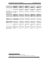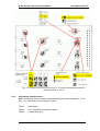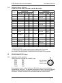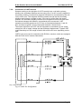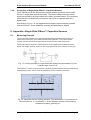
1
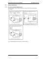
PZ 77E User Manual E-509 Position Servo-Control Module T Release: 2.8.4 T Date: 2009-02-20 This document describes the following product(s): T E-509.Lx T T Position Servo-Control Module for LVDT sensor E-509.Sx Position Servo-Control Module for SGS E-509.CxA Position Servo-Control Module for Capacitive sensors E-509.E3 Position Servo-Control Module for Single-Plate PISeca™ Capacitive Sensors E-509.E03 Signal Conditioner for Single-Plate PISeca™ Capacitive Sensors T T T T T T T T © Physik Instrumente (PI) GmbH & Co. KG Auf der Römerstr. 1 ⋅ 76228 Karlsruhe, Germany Tel. +49-721-4846-0 ⋅ Fax: +49-721-4846-299 [email protected] ⋅ www.pi.ws Physik Instrumente (PI) GmbH & Co. KG is the owner of the following company names and trademarks: PI®, PIC®, PICMA®, PILine®, PIFOC®, PiezoWalk®, NEXACT®, NEXLINE®, NanoCube®, NanoAutomation® Copyright 1999–2009 by Physik Instrumente (PI) GmbH & Co. KG, Karlsruhe, Germany. The text, photographs and drawings in this manual enjoy copyright protection. With regard thereto, Physik Instrumente (PI) GmbH & Co. KG reserves all rights. Use of said text, photographs and drawings is permitted only in part and only upon citation of the source First printing 2009-02-20 Document Number PZ 77E, Eco, Bro, Release 2.8.4 E-509_User_PZ77E284.doc X X X X X X Subject to change without notice. This manual is superseded by any new release. The newest release is available for download at www.pi.ws. H H About This Document T Users of This Manual This manual is designed to help the reader to install and operate the E-509 Position ServoControl Module. It assumes that the reader has a fundamental understanding of basic servo systems, as well as motion control concepts and applicable safety procedures. The manual describes the physical specifications and dimensions of the E-509 Position ServoControl Module as well as the procedures which are required to put the associated motion system into operation. This document is available as PDF file. Updated releases are available from www.pi.ws or email: contact your Physik Instrumente Sales Engineer or write [email protected]. X X X X X X X X HTU HTU UTH UTH Conventions The notes and symbols used in this manual have the following meanings: CAUTION Calls attention to a procedure, practice, or condition which, if not correctly performed or adhered to, could result in damage to equipment. NOTE Provides additional information or application hints. Related Documents The other system components and any software tools which might be delivered with E-509 Position Servo-Control Module are described in their own manuals. All documents are available as PDF files from www.pi.ws or by email from your Physik Instrumente Sales Engineer or [email protected]. X X X H HTU UTH H X ! E-509 Position Servo-Control Module User Manual PZ 77E Contents Introduction ................................................................. 6 1. 1.1. Safety Precautions ..................................................................... 6 1.2. Prescribed Use ............................................................................ 7 1.3. Model Survey ............................................................................... 7 1.4. Front Panels................................................................................. 9 2. Quick Start................................................................... 9 3. E-509 Design.............................................................. 11 3.1. Signal Path Diagram .................................................................. 12 3.2. Submodules ............................................................................... 13 3.3. Sensor Processing and Servo-Control Functions ...................... 14 4. E-509 Calibration Routines ....................................... 15 4.1. Static Calibration........................................................................ 15 4.2. Dynamic Calibration................................................................... 19 4.3. Adjustment for Systems with E-509.Ex PISeca™ Models ......... 19 5. Disposal..................................................................... 22 6. E-509 Technical Data ................................................. 23 6.1. Two-Plate Cap. Sensor on-board Sensor Processing ........... 25 6.2. Single-Plate Cap Sensor on-board Sensor Processing ............. 27 Pin Assignments........................................................ 30 7. 7.1. 32-Pin Main Connector, DIN 41612 ........................................... 30 7.2. SENSOR-MONITOR Output ...................................................... 31 7.3. Sensor Connections................................................................... 33 8. Appendix—Single-Plate PISeca™ Capacitive Sensors36 8.1. Measuring Principle ................................................................... 36 8.2. Measurement Range ................................................................. 37 8.3. Bandwidth .................................................................................. 37 8.4. Linearity ..................................................................................... 37 8.5. Target Plane .............................................................................. 38 8.6. Terminology ............................................................................... 38 Release 2.8.4 www.pi.ws Page 5 E-509 Position Servo-Control Module User Manual PZ 77E 1. Introduction E-509 is a displacement-sensor and position-servo-control module for PZT actuators. The module is used in the E-500-series electronics and allows controlling the position (displacement) of piezoelectric devices with nanometer resolution. It can also be installed in E-470, E-471, E-480 and E-481 high-voltage amplifier systems, giving them servo-control capability. The E-509 controller generates the input signal for the power amplifier module which actually drives the PZT. The E-509 uses the difference between target position and the actual position in a servo-loop algorithm, compensating drift and hysteresis of the PZT actuators. The effective stiffness of the actuator is significantly increased due to the rapid displacement control effected by adjusting the PZT operating voltage so as to maintain the displacement even when external forces change. Position information is provided by high-resolution sensors integrated in the mechanical stage or PZT actuator. Strain gauge sensors (SGS), LVDT sensors and capacitive sensors are supported by the E-509. The E-509 does not encompass an amplifier to supply the PZT operating voltage. High-voltage (E-507, E-508, E-470, E-471, E-480, E-481) or low-voltage amplifiers (E-503, E-505) can be used—the choice depends on the PZT type. The E-509 and amplifier are installed in the same chassis and communicate automatically over the backplane (see signal path diagram, p. 12). X X The main parts of the E-509 are the sensor signal processing circuit and a servocontroller with adjustable P-I filter and optional notch filter to allow operation close to the mechanical resonant frequency. The E-509 hardware design comprises the basic PCB module and one or two small PCB submodules for each channel. Implemented on submodules are the servo-control algorithms, and, in the case of SGS and LVDT sensor versions, the sensor processing. 1.1. ! ! Safety Precautions CAUTION—Electrostatic Hazard Electronic components are sensitive to electrostatic electricity. Take appropriate electrostatic protection measures when installing or removing boards or working on an open controller. CAUTION—High Voltage The piezo amplifiers used with this product are high-voltage devices capable of generating high output currents. They may cause serious or even lethal injury if used improperly. Take special care if connecting products from other manufactures. CAUTION—Avoid Resonance Damage ! Most of the PZT actuators used with the system described in this manual can be permanently damaged by uncontrolled resonance. The system must never be operated too close to the resonant frequency. If you hear or see resonant behavior, switch off the unit. Release 2.8.4 www.pi.ws Page 6 E-509 Position Servo-Control Module 1.2. User Manual PZ 77E Prescribed Use Based on their design and realization, E-509 modules are intended to be used installed in compatible housings, like the PI E-500/E-501 series chassis. They must not be used for applications not in conformance with this manual. X X Observe the safety precautions given in this User Manual. E-509 systems conform to Measurement Category I (CAT I) and may not be used for Measurement Categories II, III or IV. Other use of the device (i.e. operation other than instructed in this Manual) may affect the safeguards provided. X X Standard E-509 systems are designed to operate under normal ambient conditions at least as listed here. More stringent conditions given in the Specifications Table (p. 23) are, of course, also met. X X X X Indoor use Altitude up to 2000 m Temperature range 5°C to 40°C Max. relative humidity 80% for temperatures up to 31°C, decreasing linearly to 50% relative humidity at 40°C Line voltage fluctuations not greater than ±10% of the line voltage Transient overvoltages as typical for public power supply Note: The nominal level of the transient overvoltage is the standing surge voltage according to the overvoltage category II (IEC 60364-4-443). T T 1.3. Degree of pollution: 2 Model Survey 1 TPF FPT E-509.S1 PZT Servo-Control Module, one channel, for strain gauge sensors E-509.S3 PZT Servo-Control Module, three channels, for strain gauge sensors E-509.L1 PZT Servo-Control Module, one channel, for LVDT sensors E-509.L3 PZT Servo-Control Module, three channels, for LVDT sensors E-509.C1A PZT Servo-Control Module, one channel, for 2-plate capacitive sensors E-509.C2A PZT Servo-Control Module, two channels, for 2-plate capacitive sensors E-509.C3A PZT Servo-Control Module, three channels, for 2-plate capacitive sensors E-509.E3 PZT Servo-Control Module, three channels, for single-plate PISeca™ capacitive sensors E-509.E03 Signal conditioner (sensor excitation and readout) module, three channels, for single-plate PISeca™ capacitive sensors; no servo-control TP 1 PT Most SGS and LVDT versions cannot be distinguished by the front panel. Release 2.8.4 www.pi.ws TP PT Page 7 E-509 Position Servo-Control Module 1.3.1. User Manual PZ 77E Submodules (pre-installed on the E-509 2 ) E-801.1x Sensor-processing submodule for SGS sensors (present on E509.Sx/E-509.S3S) TPF FPT E-801.2x Sensor-processing submodule for LVDT sensors (present on E-509.Lx) E-802.5x Position Servo-Control submodule (present on all except E-509.E03) The submodules are described in separate manuals: E-801 submodules in PZ117E, E-802.55s in PZ150E, and all former E-802.5x versions in PZ113E. The appropriate manuals are included with your E-509 module(s). 1.3.2. Standard Accessories E-808.90 Sensor-Monitor cable: comes with three-channel SGS- and LVDTsensor versions (E-509.S3, E-509.L3) Note: The purpose of this cable is simply to split up the SENSOR MONITOR output signal (LEMO) for the three channels. The leads of this open ended cable are color coded: white = channel 1, brown = channel 2, green = channel 3, shield = GND. D-893.32 Sensor-Monitor cable: comes with each capacitive-sensor version (E-509.CxA, E-509.Ex) Note: The purpose of this cable is simply to split up the SENSOR MONITOR output signal (6-pin LEMO) to three separate BNC connectors. The cable is also specially designed for low-noise operation. The BNC connectors are each labeled with the channel number. 3214 1.3.3. Banana Plug: For single-plate PISeca™ capacitive sensor reference plane ground connection. Shown at right disassembled, before installation of lead. Fig. 1: Banana plug Single-Plate Capacitive Sensor Probes Different size sensors are available for the E-509.E03 and E-509.E3 single-plate capacitive sensor versions. The sensors must thus be ordered separately: D-510.020 PISeca™ Single-Electrode Capacitive Sensor Probe, 8 mm diameter, 20 µm nominal range, 40 µm, 50 µm and 100 µm extended ranges, D-891.01E connecting cable included D-510.050 PISeca™ Single-Electrode Capacitive Sensor Probe, 12 mm diameter, 50 µm nominal range, 100 µm, 125 µm, 250 µm extended ranges, D-891.01E connecting cable included D-510.100 PISeca™ Single-Electrode Capacitive Sensor Probe, 20 mm diameter, 100 µm nominal range, 200 µm, 250 µm, 500 µm extended ranges, D-891.01E connecting cable included See the sensor documentation for information on mounting and performance. 2 For versions and details of the submodules, refer to the E-801 Sensor Submodule User Manual (PZ 117E) and the E-802 User Manual (PZ150E or PZ 113E). The E-509.CxA and E-509.Ex have sensor-processing electronics on the main module TP PT Release 2.8.4 www.pi.ws Page 8 E-509 Position Servo-Control Module 1.4. User Manual PZ 77E Front Panels PZT-SERVO CONTROLLER SERVO ON OFL OFF SENSOR MONITOR ZERO SENSOR E-509 Fig. 2: LVDT and SGS versions share the same front panels Fig. 3: Typical front panels of the different capacitive sensor versions* *The predecessors of E-509.CxA models were E-509.Cx; they differ in SENSOR MONITOR socket. 2. Quick Start NOTE To achieve optimum measurement stability it is recommended to wait at least 30 minutes after powering up the system. 2.1.1. General Procedure This quick start assumes that your E-509 was ordered with an appropriate chassis and was calibrated at the factory with the PZT actuators with which it will be operated. To put the system into operation, proceed as follows: 1. Make sure the control unit in which the E-509 is installed is powered down. 2. Connect the PZT actuator sensor cables to the E-509 servo-controller. With single-plate capacitive sensor systems, see Section 2.1.2 below. On multichannel units, make sure that each PZT is connected to the channel with which it was calibrated (see label affixed to back of chassis). On 2-plate capacitive sensor systems, make sure that the “Probe” and “Target” sensor cables are not interchanged. X Release 2.8.4 www.pi.ws X Page 9 E-509 Position Servo-Control Module User Manual PZ 77E 3. Connect the PZT voltage supply cables to the power amplifier module (in the same chassis, near the E-509). Again, in multi-axis systems, make sure the proper PZTs are connected to the proper channels. ! CAUTION—High Voltage The piezo amplifiers used with this product are high-voltage devices capable of generating high output currents. They may cause serious or even lethal injury if used improperly. Take special care if connecting products from other manufactures. ! CAUTION—Avoid Resonance Damage Most of the PZT actuators used with the system described in this manual can be permanently damaged by uncontrolled resonance. The system must never be operated too close to the resonant frequency. If you hear or see resonant behavior, switch off the unit. 4. If you have a computer control and/or display module in the system (e.g. E-516 or E-517), consult its User Manual for information on commanding the system and setting servo-control parameters. In particular, make sure the front-panel Servo-Control switch is properly set for the type of operation you require. 5. Power up the system. If you see or hear resonant behavior, power down immediately and check the servo-control parameters. See the “Dynamic Calibration” Section on p. 19 for more information. X X 2.1.2. X X Systems with E-509.Ex PISeca™ Models NOTE Motion of the connecting cable should be avoided because of capacitive influences. If possible, the application should be designed with sensor probe always at rest and the target the moving part of the system. 1. Mount the sensor probe in your intended application as described in the Technical Note D510T0001. Note that the minimum allowable probe-to-target gap is 10 µm. A minimum gap of 15 µm is recommended. CAUTION ! Take care not to shift the sensor probe when connecting the cable! 2. 3. Connect the sensor probe to the Sensor In socket of the E-509.Ex electronics unit using the D-891.01E cable (comes with the sensor). Make sure that each sensor probe is connected to the channel with which it was calibrated (see label affixed to back of chassis) Connect the target surface to the Sensor Gnd socket on the front of the E509.Ex (mating banana plug included). Make sure that each target surface is connected to the channel with which the corresponding sensor probe was calibrated (see label affixed to back of chassis) Release 2.8.4 www.pi.ws Page 10 E-509 Position Servo-Control Module 4. User Manual PZ 77E Connect the included E-808.90 sensor monitor cable to the Sensor Monitor 13 socket. The sensor monitor signal shows the current position of the sensor probe in relation to the target and the selected measurement range. See Section 4.3.3 for details on how to adjust target surface and probe X X 3. E-509 Design The E-509 module is designed to plug into a compatible PI chassis (e.g. E-500, E501 or E-470, but not E-50x.621). There it operates in conjunction with other modules such as power amplifiers and display or remote control units. See the E-500/E-501 User Manual (PZ 62E) and the manuals of other devices in your system for details. Most questions about E-509 operation can be answered by reference to the signal path diagram in the next section. Release 2.8.4 www.pi.ws Page 11 E-509 Position Servo-Control Module 3.1. User Manual PZ 77E Signal Path Diagram Fig. 4: Signal path (only one channel shown) in a system with an E-509 ServoController, a PZT power amplifier and an E-516 Computer Interface and Display Module. Note that "Control In" and "DC-offset" on the amplifier module do not control the amplifier directly, but only determine “Control Out” for the other modules. Some amplifiers can invert these signals, and the E-509 output can be inverted or shifted, but if Servo is ON, the E-509 “Target In” must be in the 0 to 10 V range if Servo is ON. Note also that the E-802 servo mode is determined by a combination of the toggle switch position and the state commanded by the E-516. Note that E-517 Interface and Display modules act in the same way as E-516s. Release 2.8.4 www.pi.ws Page 12 E-509 Position Servo-Control Module 3.2. User Manual PZ 77E Submodules Some functions of the E-509 are implemented on plug-in submodules 3 , as discussed in the following sections. It should not be necessary to remove or replace the submodules, but if you ever do so, be sure to face the component sides as illustrated, (Fig. 5). TPF X FPT X SGS and LVDT Versions Capacitive Sensor Servo Versions Fig. 5: Submodule locations on E-509 modules. Note also sensor gain potentiometer locations 3.2.1. E-509.S1 and E-509.L1 These single-channel versions have one servo-control and sensor submodule each. The submodules location is identical with the layout shown in Fig. 5, but only for one channel each. X 3.2.2. E-509.S3 and E-509.L3 These 3-channel versions are depicted at left in Fig. 5, and have three servocontrol and three sensor submodules each. X 3.2.3. X X E-509.CxA and E-509.E3 The E-509.CxA and E-509.E3 versions also have one servo-control submodule per channel. The sensor processing electronics is implemented on the main board rather than on a submodule (Fig. 5 right). X X See Fig. 9 on page 25 for the full layout of a three-channel E-509.C3A or Fig. 11 on p. 28 for the E-509.E3. X X X 3.2.4. X X X X X E-509.E03 The E-509.E03 does sensor processing only and has no servo-controller and no submodules. Its layout is otherwise the same as the E-509.E3 (Fig. 11). X TP 3 PT X Except on the E-509.E03 which has no servo-controller and no submodules. Release 2.8.4 www.pi.ws Page 13 E-509 Position Servo-Control Module 3.3. User Manual PZ 77E Sensor Processing and Servo-Control Functions The E-509 modules normally come pre-installed in an appropriate PI chassis (except for OEM versions). The system is calibrated at the factory with the associated PZT actuators. If, however, you should need to recalibrate your system, see Section 4 and the E802 Servo-Control Submodule User Manual. X 3.3.1. X Sensor Processing Electronics SGS versions have E-801.1x submodules which provide DC sensor excitation and readout. LVDT versions have E-801.2x submodules which provide AC sensor excitation. They can also be connected to SGS sensors if necessary. On multi-channel E509s, the LVDT excitation frequencies are synchronized by the appropriate use of master and slave E-801.2x versions or jumper settings. Should you ever need to make any adjustments on the sensor submodules, refer to the E-801 User Manual for more details. Capacitive sensor versions have the sensor electronics on the E-509. See Section 6.1 or 6.2 of this manual for details. X 3.3.2. X X X E-802 Position Servo-Control Submodules The E-802 submodule processes the control signal for the amplifier driving the piezoelectric translators. Slew rate limitation, notch filter and servo-control loop are all implemented on the E-802. The servo-loop logic compares the TARGET IN and the sensor signal (current position) to generate the SERVO-CONTROL OUT amplifier control signal using an analog proportionalintegral (P-I) algorithm. For details see the signal path diagram, Fig. 4, on 12. X X X X The E-802 can operate in either servo OFF mode or servo ON mode. The mode is determined by a combination of the (active-low) SERVO ON/OFF signal and the front-panel SERVO TOGGLE SWITCH: for servo OFF mode, both must be in the OFF condition (see Signal Path diagram, p. 12). With the E-802.55 and higher versions of the E-802, the notch filter and slew rate limiter remain active even when servo-mode is OFF. This can cause a ±5% shift of the open-loop output voltage to occur when the notch filter frequency is changed. X X For more details and calibration procedures, see Section 4 and the E-802 Servo-Control Submodule User Manual. X Release 2.8.4 www.pi.ws X Page 14 E-509 Position Servo-Control Module User Manual PZ 77E 4. E-509 Calibration Routines For most applications, only the zero point has to be realigned from time to time to compensate for temperature changes. Further adjustments are not required and not recommended as long as system components are not exchanged or modified. NOTE All basic calibration adjustments are done in PI lab before shipment. The PZT system is delivered ready for operation. Except for occasional zero-point adjustment, it should not be necessary to calibrate the system. Therefore calibration should only be done if the controller/actuator configuration is changed or elements are replaced. The full calibration and adjustment procedure for the E-509 Position Servo-Control Module includes static calibration (zero point and sensor gain adjustment) and dynamic calibration (servo-loop, slew rate and step response). In addition, on the capacitive sensor versions, the ILS (integrated linearization system) can be adjusted to minimize 2nd order polynomial non-linearities. Calibration must be performed separately on each channel. NOTE The PZT actuator is calibrated in conjunction with a particular E-509 control module: the devices then belong together. Replacement of either one or the other requires new calibration runs to obtain the specified system accuracy. 4.1. Static Calibration Proper static calibration makes it possible to accurately drive the PZT system to absolute positions with an external analog control signal running over a 10 V range and without reaching the output voltage limits of the amplifier and causing overflow conditions. Static calibration consists of zero-point adjustment and static gain adjustment— and for capacitive sensor versions—ILS adjustment. The adjustments are to some degree interdependent and should be repeated until stable settings are obtained. NOTE Zero-point adjustment is the only calibration operation regularly required in most application environments. The following subsections describe the static calibration procedure for one channel. Note that calibration must be performed separately on each channel. 4.1.1. Equipment Needed Zero-point adjustment: For calibration in analog (offline) operation an adjustable voltage source from 0 to +10.0000 V is needed. If a display or computer-control module (e.g. E-516 or E-517) is present in the system, zero-point adjustment can be performed without additional equipment. Otherwise, a precision voltmeter is required. Release 2.8.4 www.pi.ws Page 15 E-509 Position Servo-Control Module User Manual PZ 77E Static gain (sensor range) adjustment: Static PZT displacement calibration requires an external expansion gauge with appropriate resolution (e.g. 0.01 µm for a P-841.30 actuator) and a precision voltmeter. The accuracy of calibration depends on the resolution of the external measurement system. We recommend using a system with an accuracy of at least 100 nm and a resolution of 10 nm. For calibration in analog (offline) operation an adjustable voltage source from 0 to +10.0000 V is needed. Since the E-509 module has to be brought out of the chassis to permit access to the appropriate adjustment elements, a 32-pin extension board (P-895.00, not included) is also required. 4.1.2. Zero-Point Adjustment Proper zero-point adjustment ensures that the full output voltage swing of the amplifier can be used without reaching the output voltage limits of the amplifier and causing overflow conditions, both in open-loop and closed-loop operation. The zero-point is adjusted with the ZERO potentiometer, accessible through a labeled hole in the E-509 front panel. This potentiometer shifts the output of the sensor processing circuitry and hence the values on the "Sensor out," "Monitor out" and servo-loop sensor-input lines (see Fig. 4). X X 1 Before powering up the system, make sure the PZT actuator is mounted in the same way and with the same load as during normal operations in the application. In multi-axis systems, make sure the PZTs are always connected to the same controller modules. 2 If you use your own LVDT or capacitive sensors, adjust the sensor mechanical zero position (LVDT core or capacitor plate position). For details see the sensor or sensor-submodule documentation. 3 Decide whether you want to calibrate in computer-controlled mode (online) or in "analog" mode (offline). Online and offline operation must not be mixed during calibration. If you choose offline operation, make sure any computer interface module (e.g. E-516 or E-517) is set to "offline". The following steps describe offline operation—if you choose online operation, use computer commands in place of the control voltage and DC-offset to command voltages and position (you do not need an external voltage source for computercontrolled calibration). 4 Make sure the control input (on the amplifier module) is 0 V. 5 Set the switch on E-509 front panel to Servo OFF (required in computer mode also). 6 Power up the system. Make sure that any computer-control module is consistent with servo OFF. 7 Turn the DC-OFFSET potentiometer on the amplifier module full clockwise and than back full counterclockwise (0 V) to exercise the PZT. 8 Adjust the ZERO potentiometer so that the sensor-monitor signal is 0 V. For offline calibration, read it either with a voltmeter on the SENSOR MONITOR socket or on a display module in the system. The zero adjustment is now close enough to allow switching on servo-control. 9 Switch the channel to closed-loop (SERVO ON). 10 If no display module (e.g. E-516 or E-517) is installed, connect a voltmeter to the PZT socket (PZT output voltage) on the amplifier in parallel with the PZT. Release 2.8.4 www.pi.ws Page 16 E-509 Position Servo-Control Module User Manual PZ 77E 11 Again using the ZERO potentiometer, adjust the PZT output voltage as follows: For HV amplifiers: set voltage to approx. -50 V For LV amplifiers: set voltage to approx -5 V The zero-point setting is now close enough to allow checking of the PZT output range 12 Check the PZT output range by applying a voltage which goes from 0 V to +10 V to the CONTROL INPUT and watching the voltage at PZT socket in parallel with the PZT. a) If the output voltage ranges from -10 V to +100V, then zero-point adjustment is finished. b) If the output voltage exceeds the range from -10 V to +100 V, the zero point should be shifted so that the PZT-output voltage range is in the center of the amplifier output range. For this purpose, return the control input to 0 V and repeat step 11 using a slightly different value, e.g. -10 V for an LVPZT. X X Example: Assume the LVPZT used requires 90 V to achieve the nominal displacement of 100 µm. Furthermore take into account that the maximum voltage at the LVPZT should not exceed +100 V in order to maintain a long lifetime. The E-503/E-505 LVPZT amplifiers have an output range from -20 V to +120 V. In this case, the zero position PZT voltage can be set within the range from -10 V to +10 V. Then, the nominal displacement of 100 µm will be reached with PZT out in the +80 V to 100 V range., i.e. there is a cushion of ±10 V available to keep the amplifier from clipping the output when the controller is within the nominal servo-control range. 4.1.3. ! Second Order Polynomial Linearization (cap sensor versions only) The capacitive sensor electronics on the E-509.CxA and E-509.Ex versions includes a trim pot (ILS) for minimizing second-order polynomial non-linearity. To adjust the ILS proceed as follows: 1 Before powering up the system, make sure the PZT actuator is mounted in the same way and with the same load as during normal operations in the application. In multi-axis systems, make sure the PZTs are always connected to the same controller modules. 2 Mount an external gauge to measure the PZT displacement. Only if the external measurement system offers higher precision than the capacitive sensor can the maximum performance be achieved. With PZT power amplifier powered down, the external gauge should read 0; if it does not, note the offset and subtract it from subsequent readings. CAUTION—Electrostatic Hazard Modular Boards Subject to Damage T Electronic components are sensitive to electrostatic electricity. Take appropriate electrostatic protection measures when installing or removing boards or working on an open controller. 3 Remove the E-509 from the chassis and reconnect through the extension bracket (not included). To remove the module, proceed as follows: a) Loosen the two Phillips screws on the front panel. b) Using the grip at the bottom of the front panel, pull the module out of the chassis. Release 2.8.4 www.pi.ws Page 17 E-509 Position Servo-Control Module 4 Scan the voltage at CONTROL INPUT from 0 V to +10 V and read the PZT displacement using an external gauge. 5 Adjust the Integrated Linearization System (ILS) by turning the ILS potentiometer (see Fig. 9, p. 25) and observe the linearity of the PZT displacement. X 4.1.4. User Manual PZ 77E X X X Static Gain Adjustment It should only be necessary to readjust the static gain if system components have been exchanged or altered. Before doing so, reading the detailed description of the sensor-processing system is recommended (for SGS and LVDT the E-801 Sensor Submodule User Manual, for capacitive sensors the manual or technical note covering the sensors. The objective of static gain adjustment is to ensure that the PZT actuator expands to its nominal expansion when a control signal input of 10 V is applied (amplifier module DC-offset set to 0). The zero-point must be appropriately set before the static gain adjustment can be done. This is an iterative process. The static gain adjustment procedure is as follows: ! 1 Before powering up the system, make sure the PZT actuator is mounted in the same way and with the same load as during normal operations in the application. In multi-axis systems, make sure the PZTs are always connected to the same controller modules. 2 Mount an external gauge to measure the PZT displacement. (with PZT power amplifier powered down, the external gauge should read 0; if it does not, note the offset and subtract it from subsequent readings) CAUTION—Electrostatic Hazard Modular Boards Subject to Damage T Electronic components are sensitive to electrostatic electricity. Take appropriate electrostatic protection measures when installing or removing boards or working on an open controller. 3 Remove the E-509 from the chassis and reconnect through the extension bracket (not included). To remove the module, proceed as follows: a) Loosen the two Phillips screws on the front panel. b) Using the grip at the bottom of the front panel, pull the module out of the chassis. 4 Decide whether you want to calibrate in computer-controlled mode (online) or in "analog" mode (offline). Online and offline operation must not be mixed during calibration. If you choose offline operation, set any computer interface module (e.g. E-516 or E-517) to "offline". The following steps describe offline operation—if you choose online operation, use computer commands in place of the control voltage and DC-offset to command voltages and position (you do not need an external voltage source for computer-controlled calibration). 5 Set the corresponding switch on the E-509 front panel to Servo OFF. 6 Make sure the DC-Offset potentiometer on amplifier module is set to zero (full counterclockwise). 7 Power up the system. Make sure that any computer-control module is consistent with the servo OFF state. Release 2.8.4 www.pi.ws Page 18 E-509 Position Servo-Control Module 8 Scan the voltage at CONTROL INPUT from 0 V to +10 V and read the PZT displacement using the external gauge. With +10 V the external gauge should show the PZT at about nominal expansion. Adjust with the sensor gain trim potentiometer (Fig. 6). Sensor gain is now close enough to allow switching servo ON. X 9 User Manual PZ 77E X Switch servo ON. 10 Adjust the sensor monitor signal to exactly 10.000 V using the gain adjustment potentiometer on the E-802 servo submodule (different versions of this submodule exist, see the E-802 User Manual for gain adjustment on your unit) 11 Adjust the PZT position to the nominal expansion value using the sensor gain adjustment (Fig. 6) from step 8. Now, because servo ON, the sensor monitor value will not change! X X X X 12 Repeat the last two steps until you get stable readings If the Gain settings have been changed, the zero-point adjustment starting with section 4.1.2 should be repeated, and then the static gain rechecked. X X Sensor gain adjustment SGS and LVDT Versions Capacitive Sensor Versions C Fig. 6: Sensor gain adjustment location 4.2. Dynamic Calibration Dynamic performance of the PZT system is determined by the maximum output current of the amplifier and by the mechanical properties of the PZT mechanics, like moving mass, damping and resonant frequencies. Dynamic calibration optimizes step response and suppresses resonance, overshoot, and oscillation. These servo-loop, notch filter and slew-rate limitation setting procedures are all described in detail in the E-802 Servo-Control Submodule User Manual. 4.3. Adjustment for Systems with E-509.Ex PISeca™ Models 4.3.1. Calibrated System Calibration routine ensures linearity of the output signal over the measurement range within the specified linearity for the calibrated range setting. The linearity error of a measurement is the maximum deviation of the output from a straight line between minimum and maximum output. If ordered together, a PISeca™ single-electrode, capacitive measurement system consists of the sensor probe (D-510 series), the signal conditioner electronics (E509.Ex) and connecting cables. This system is calibrated together at PI and shipped with a corresponding calibration sheet. During calibration, the measurement range and bandwidth are preset to the appropriate values. In the calibrated range the minimum probe-to-target gap equals 50% and the maximum gap 150% of the measurement range value. Release 2.8.4 www.pi.ws Page 19 E-509 Position Servo-Control Module User Manual PZ 77E If not ordered otherwise, the following settings are used for calibration (see p. 27 for different settings and location of the adjustment elements): X Bandwidth 3 kHz Sensor output voltage range 0 to 10 V Measurement range Standard extension range factor of 1 used for calibration; resulting range depends on nominal range of the sensor probe Environmental conditions Room temperature 22°C Parallelism probe surface to target surface Tilt < 700 µrad X Fig. 7: Definitions: due to the system design, the numerical values of mid-range (working) distance and measurement range are the same NOTE The zero point for the output voltage given by the electronics may differ up to 10% for different specimen of the E-509.Ex. Thus the mid-range distance may vary from the electronic zero point by up to 10%. See calibration sheet for details. Release 2.8.4 www.pi.ws Page 20 E-509 Position Servo-Control Module 4.3.2. User Manual PZ 77E Sensor Monitor Signal For each sensor channel, the sensor monitor signal available on the E-509.Ex front panel indicates the gap size between target surface and sensor probe, known as the probe-to-target gap. The sensor monitor signal can be used to adjust target and probe (see Section 4.3.3 below for how to proceed). X X Fig. 8: Relation of sensor (monitor) signal and measurement range The linearity specified in the datasheet is only valid for the measurement range setting with which the system was calibrated (default extension factor = 1). The system is calibrated in such a way that the minimum monitor voltage is output when the minimum gap is reached and the maximum monitor voltage when the upper gap limit is reached. The default range of the sensor output and hence of the monitor signal is 0 to 10 V. See p. 27 for different measurement and sensor output range values. X X If the sensor monitor signal is outside of the valid sensor output range, the measurement is outside the calibrated range, and the specified linearity is no longer assured. NOTE Differing from the standard, sensor probes D-510.020 covering a nominal measurement range of 20 µm are calibrated for 15 to 30 µm. Nevertheless, the sensor monitor signal covers the full range (10 to 20 µm). 4.3.3. How to Adjust Target and Probe Do not interchange signal conditioners, connecting cables and/or sensor probes after they have been calibrated together. The probe ID serial number is noted on labels affixed to the connecting cable and to the signal conditioner. Proceed as follows to adjust target and probe for a PISeca™ sensor channel. Preparation, optionally, requires removing the E-509.Ex module from the chassis (see p. 27 for details): X X 1. Check the setting for the sensor output range (and hence the range of the sensor monitor signal). See p. 27 for details. Default range is 0 to 10 V X X 2. Check the setting for the measurement range extension factor. Default factor is 1 3. Check the polarity setting for the sensor output. See p. 27 for details. Default polarity is positive X Release 2.8.4 www.pi.ws X Page 21 E-509 Position Servo-Control Module User Manual PZ 77E Adjustment procedure, valid with default settings for sensor output range, measurement range and polarity: 1. Mount sensor probe as described in the Technical Note D510T0001. Note that the minimum allowable probe-to-target gap is 10 µm. A minimum gap of 15 µm is recommended 2. Turn the corresponding Zero potentiometer fully counterclockwise 3. Adjust sensor probe and target so that the gap is equal to the nominal measurement range (e.g. with D-510.050 = 50 µm). The sensor monitor signal then must be approx. 0 V 4. Adjust the Zero potentiometer so that the sensor monitor signal is approx. 5 V 5. Reduce the gap between sensor probe and target so that it is half the nominal measurement range (e.g. with D-510.050 = 25 µm). The sensor monitor signal should then be 0 V 6. Enlarge the gap between sensor probe and target so that it is 1.5 times the nominal measurement range (e.g. with D-510.050 = 75 µm). The sensor monitor signal should now be 10 V NOTE When the sensor output voltage range selection is changed, the voltage value may be up to 2% different from the expected value. 5. Disposal In accordance with EU directive 2002 / 96 / EC (WEEE), as of 13 August 2005, electrical and electronic equipment may not be disposed of in the member states of the EU mixed with other wastes. To meet the manufacturer’s product responsibility with regard to this product, Physik Instrumente (PI) GmbH & Co. KG will ensure environmentally correct disposal of old PI equipment that was first put into circulation after 13 August 2005, free of charge. If you have such old equipment from PI, you can send it to the following address postage-free: Physik Instrumente (PI) GmbH & Co. KG Auf der Römerstr. 1 76228 Karlsruhe, Germany Release 2.8.4 www.pi.ws Page 22 E-509 Position Servo-Control Module User Manual PZ 77E 6. E-509 Technical Data E-509.C1A / E-509.C2A / E-509.C3A E-509.L1 / E-509 L3 E-509.S1 / E-509.S3 E-509.E3 E-509.E03 Function Sensor electronics and position servocontroller Sensor electronics and position servocontroller Sensor electronics and position servocontroller Sensor electronics and position servocontroller Sensor electronics only, no servo Number of axes 1/2/3 1/3 1/3 3 3 Sensor Servo characteristics P-I (proportional- P-I (proportional- P-I (proportional- P-I (proportional- none integral; analog) integral; analog) integral; analog) integral; analog) + notch filter + notch filter + notch filter + notch filter Sensor type 2-plate capacitive LVDT Strain gauge PISeca™ single- PISeca™ singleplate capacitive plate capacitive Sensor channels 1/2/3 1/3 1/3 3 Measurement range extension 0.56, 0.68, 0.75, 1.0 (default), 1.25, 2.13, 3 1 (default), 2, 2.5 1 (default), 2, 2.5 &5 &5 Sensor bandwidth 0.3 to 3 kHz, jumper settable; up to 10 kHz on request 0.3 to 10 kHz, jumper settable 0.3 to 10 kHz, jumper settable Noise factor 4 0.115 ppm/√Hz see note 5 0.14 ppm/√Hz see note 0.14 ppm/√Hz see note possible possible < 1 mV/C° < 1 mV/C° TPF FPT TPF FPT Ext. synchronization possible Temperature drift -30 ppm/C° see note 6 TPF 3 X5X n.a. FPT 7 Static resolution <0.001% Dynamic resolution <0.0025% Linearity @ nominal range X5X Linearity error < 0.1% 8 TPF TPF <0.001% FPT X7X <0.1% X7X <0.0025% <0.1% TPF X7X 9 FPT FPT Interface and operation Rear connector 32-pin connector, 32-pin connector, 32-pin connector, 32-pin connector, 32-pin connector, DIN 41612 DIN 41612 DIN 41612 DIN 41612 DIN 41612 Sensor output 0 – 10 V 10 Sensor output impedance (DC) 100 k-ohm 4 TP FPT 0 V – 10 V X10X 0 V – 10 V X10X 0 V – 10 V X10X 0 V – 10 V X10X Values measured with reference capacitor and 1m cable length In nominal measurement range PT 5 TP TPF PT 6 ppm (parts per million), relative to full measurement range Bandwidth: static 300 Hz, dynamic 3 kHz 8 Values are measured with capacitive sensor D-100.00. 9 Linearity over nominal range with D-510.020 in 1.0 range extension is 0.2% TP PT 7 TP PT PT TP TP PT P 10 P Can be shifted and/or inverted to -10 to 0 V or -5 to +5 V for special applications Release 2.8.4 www.pi.ws Page 23 E-509 Position Servo-Control Module E-509.C1A / E-509.C2A / E-509.C3A Sensor connector E-509.L1 / E-509 L3 User Manual PZ 77E E-509.S1 / E-509.S3 E-509.E3 E-509.E03 LEMO LEMO LEMO LEMO LEMO EPL.00.250.NTD ERA.0S.304.CLL ERA.0S.304.CLL ECP.00.650.NLL ECP.00.650.NLL see note 11 see note .543 Triax .543 Triax TPF Sensor monitor 0 V – 10 V X10X FPT 0 V – 10 V X10X X11X 0 V – 10 V X10X 0 V – 10 V X10X 0 V – 10 V X10X Sensor monitor output 10 k-ohm impedance (DC) Sensor monitor socket LEMO 6-pol. FGG.0B.306.CL AD56 BNC / BNC / LEMO 6-pol. ERA.05.303.CLL ERA.05.303.CLL FGG.0B.306.CL AD56 LEMO 6-pol. FGG.0B.306.CL AD56 Linearization ILS ILS ILS ILS Target ground connector LEMO EPL.00.250.NTD banana socket banana socket +5 bis +40 °C +5 bis +40 °C ILS Miscellaneous Operating temperature +5 bis +50 °C range +5 bis +50 °C +5 bis +50 °C Dimensions Euroboard, one 7 Euroboard, one 7 Euroboard, one 7 Euroboard, one 7 Euroboard, one 7 T slot wide, 3 H T slot wide, 3 H T slot wide, 3 H T slot wide, 3 H T slot wide, 3 H high high high high high Mass 0.2 / 0.25 / 0.35 kg 0.2 / 0.35 kg 0.2 / 0.35 kg 0.3 kg 0.3 kg ±15 V ±15 V ±15 V ±15 V ±15 V Operating voltage 12 TPF 11 TP PT TP 12 PT FPT This signal also on DIN 41612 32-pin rear connector Requires E-530/E-531 power supply (as in compatible PI chassis, e.g. E-500/E-501) Release 2.8.4 www.pi.ws Page 24 E-509 Position Servo-Control Module 6.1. User Manual PZ 77E Two-Plate Cap. Sensor on-board Sensor Processing The E-509.CxA versions have the sensor processing on the main board. The adjustment elements affecting sensor processing which are described in this section are for use only if the controller/actuator configuration is changed or elements are replaced. Do not hesitate to consult with PI before proceeding with calibration procedures. See also the “E-509 Calibration Routines” section on page 15. X X X X Note that the zero adjust trim potentiometers (TRx02) are accessible through the front panel (ZERO; see Fig. 3 on page 9). Adjustment of other elements involves removing the module from the chassis. X X X X Fig. 9: E-509.C3A Layout showing location of sensor processing adjustment elements. Note: Numbering of jumpers and potentiometers is channel-specific: “x” can be 1, 2 or 3 depending on the channel number. 6.1.1. Adjustment Potentiometers: TRx01: Sensor gain TRx02: Zero, accessible through front panel TRx03: Linearization (ILS) Release 2.8.4 www.pi.ws Page 25 E-509 Position Servo-Control Module 6.1.2. User Manual PZ 77E Jumpers and On-Board Switch JPx01–JPx06: Code Selection for measurement range, see table below: Default setting: 1.0 factor of extention of measurement range no measurement 0.56 0.68 0.75 1.0 1.25 2.13 JPx06 JPx05 JPx04 JPx03 JPx02 JPx01 Jumper Position Dwg: code.wmf JPx07: Output Polarity Setting: positive / negative Default setting: positive _ _ + + Positive Negative Position of the Jumper JP107,JP207,JP307 Polarity of Output JPx08 and JPx09: Output Offset setting: Default setting: 0 V ~ 10 V For stable measurements, the front-panel zero potentiometer should be set to either CW or CCW end position. Select the desired offset by setting the jumpers. Switch SWx01: Bandwidth Setting Default setting: 1500Hz (position C) Note: All numbers for jumpers and switches refer to channel 1, channel 2 or channel 3. Release 2.8.4 www.pi.ws Page 26 3 E-509 Position Servo-Control Module User Manual PZ 77E Jumper Settings for Master and Slave On systems with multiple E-509s or another timing source, the excitation frequencies are synchronized by the appropriate use of jumpers for master and slave. JP1 and JP2 both set to same side: left=Master, right=Slave Default setting: SLAVE Fig. 10: Capacitive sensor versions Master/Slave jumper setting (upper right of board); see Fig. 16 for signal routing X Note: X In SLAVE position the internal clock is disabled, i.e. an external clock (such as that in an E-516 or E-517 Display Module) is required. If an external clock is not available, the jumpers must be set to MASTER. Attention: If an external clock is used while the jumpers are set at MASTER, there may be interference. If that occurs, check for the correct jumper settings. 6.2. Single-Plate Cap Sensor on-board Sensor Processing The E-509.E3 and E-509.E03 versions for use with PISeca™ single-plate capacitive sensors also have the sensor processing on the main board. The adjustment elements affecting sensor processing which are described in this section are for use only if the controller/actuator configuration is changed or elements are replaced. Do not hesitate to consult with PI before proceeding with calibration procedures. See also the “E-509 Calibration Routines” section on page 15. X X X X Note that the zero adjust trim potentiometers (TRx02) are accessible through the front panel (ZERO; see Fig. 3 on page 9). Adjustment of other elements involves removing the module from the chassis. X ! X X X CAUTION—Electrostatic Hazard Modular Boards Subject to Damage T Electronic components are sensitive to electrostatic electricity. Take appropriate electrostatic protection measures when installing or removing boards or working on an open controller. Release 2.8.4 www.pi.ws Page 27 E-509 Position Servo-Control Module User Manual PZ 77E Fig. 11: E-509.E3 and E-509.E03 layout (“x” in jumper designations stands for channel number: 1,2 or 3) 6.2.1. Adjustment Potentiometers: Note: Numbering of some jumpers and potentiometers is channel-specific: “x” can be 1, 2 or 3 depending on the channel number TRx01: Sensor gain TRx02: Zero, accessible through front panel TRx03: Linearization (ILS) Release 2.8.4 www.pi.ws Page 28 E-509 Position Servo-Control Module 6.2.2. User Manual PZ 77E Jumpers and on-board Switch JP101, JP110 and JP111: Measurement Range Extension Factor Together these jumpers determine the factor applied to the measurement range. Supported are settings for 1 (default), 2, 2.5 and 5 times the standard range of the sensor head used. Corresponding settings are shown in Fig. 11. X X Switch SWx01: Sensor bandwidth setting Standard values are 300 Hz, 3 kHz (default) or 10 kHz; corresponding positions show in Fig. 11. X X JP1 & JP2: Master and Slave (Internal / External Clock) Both jumpers must be set to the same side (one enables/disables the internal clock, the other routes the clock signal). Default setting is SLAVE, i.e. to the right, shorting 2-3, as shown in Fig. 11. X X In SLAVE position an external clock (such as that in an E-516 or E-517 Display Module) is required. If an external clock is not available, the jumpers must be set to MASTER. If an external clock is used while the jumpers are set at MASTER, there may be interference. If that occurs, check for the correct jumper settings. Note: JP107: Polarity If JP107 is set to negative, the output signal is inverted; if SERVO-CONTROL OUT (Fig. 4) is to be used by standard PI electronics this will not be necessary. X X JP108, JP109: Output Offset Supported sensor output ranges are 0 to 10V (default, should be used with standard applications), -5 to +5 V and -10 to 0 V. Settings shown in Fig. 11. X Release 2.8.4 www.pi.ws X Page 29 E-509 Position Servo-Control Module User Manual PZ 77E 7. Pin Assignments 7.1. 32-Pin Main Connector, DIN 41612 7.1.1. LVDT and SGS 3-Channel (E-509.S3, E-509.L3) Pin No. Function Pin No. Function 2a 4a 6a 8a 10a 12a 14a 16a 18a 20a 22a 24a 26a 28a 30a 32a GND internal use IN: +15 V IN: -15 V Sync LVDT+** internal use (Bus_A) OUT: Display ch2 internal use (Bus_B) internal use (BUS_Vcc) IN: Control ch1 IN: Control ch3* Sync CAP-ref IN: VC/EC ch2 OUT: Overflow ch1 OUT: Overflow ch3* GND 2c 4c 6c 8c 10c 12c 14c 16c 18c 20c 22c 24c 26c 28c 30c 32c GND OUT: ch1 (control) IN: +15 V IN: -15 V Sync LVDT-** OUT: ch2 (control) OUT: Display ch1 OUT: Display ch3* internal use (BUS_GND) OUT: Control ch3* IN: Control ch2 Sync CAP input IN: VC/EEC ch1 IN: VC/EC ch3* OUT: Overflow ch2 GND ** LVDT signals meaningless on SGS versions Note: Pins labeled with "nc" may be used internally and must not be connected externally. 7.1.2. LVDT and SGS 1-Channel Versions (E-509.S1, E-509.L1) Pin No. Function Pin No. Function 2a 4a 6a 8a 10a 12a 14a 2c 4c 6c 8c 10c 12c 14c GND OUT: ch1 (control) IN: +15 V IN: -15 V Sync LVDTnc OUT: Display ch1 GND internal use IN: +15 V IN: -15 V Sync LVDT+ internal use (Bus_A) nc 16a internal use (Bus_B) 16c nc 18a internal use (BUS_Vcc) 18c internal use (BUS_GND) 20a IN: Control ch1 20c nc 22a nc 22c nc 24a Sync. CAP-ref 24c Sync.CAP-input 26a nc 26c IN: VC/EEC ch1 28a OUT: Overflow ch1 28c nc 30a nc 30c nc 32a GND 32c GND Note: Pins labeled with "nc" may be used internally and must not be connected externally. Release 2.8.4 www.pi.ws Page 30 E-509 Position Servo-Control Module 7.1.3. User Manual PZ 77E Capacitive Sensor Versions (E-509.C1A, E-509.C2A, E-509.C3A, E-509.E3, E-509.E03) Function on Pin No. .C3A, .Ex** .C2A .C1A * 2a GND * 4a n.c. * 6a + 15 V * 8a - 15 V * 10a n.c. * 12a internal use 14a 16a Function on Pin No. .C3A, Ex** .C2A .C1A 2c GND * 4c Control signal output CH1 * * 6c + 15 V * * * 8c - 15 V * * * 10c n.c. * * * * 12c Control signal output CH2 * n.c. Display CH2 * n.c. 14c Display CH1 * * internal use * n.c. 16c Display CH3 n.c. n.c. 18a internal use n.c. n.c. 18c internal use * * 20a Control signal input CH1 * * 20c Control signal output CH3 to JP210, pin 1 n.c. 22a Control signal input CH3 to JP210, pin 2 n.c. 22c Control signal input CH2 * n.c. P P P P * P * P P P * 24a n.c. * * 24c SYNC * * 26a Servo ON/OFF,ch2 * n.c. 26c Servo ON/OFF, ch1 * * 28a overflow CH1 * * 28c Servo ON/OFF,ch3 n.c. n.c. 30a overflow CH3 n.c. n.c. 30c overflow CH2 * n.c. 32a n.c. * * 32c n.c. * * * Same as on E-509.C3A ** E-509.E03 has no servo-controller and hence all servo-related pins are not connected n.c. : No Connection: may be used on the backplane and must not be connected. JP210 shorted on E-509.C2A (default): connects CH3 input to CH3 output (i.e. CH3 bypassed) 7.2. SENSOR-MONITOR Output 7.2.1. Capacitive sensor versions: LEMO Connector (FGG.0B.306.CLAD56), 6-pin pin 1 ch1+ pin 2 ch1pin 3 ch2+ pin 4 ch2pin 5 ch3+ pin 6 ch3shield: GND Fig. 12 Six-pin LEMO sensor monitor socket Each capacitive sensor version (E-509.CxA, E-509.Ex) comes with the D-893.32 Sensor-Monitor cable (2m). The purpose of this cable is simply to split up the SENSOR MONITOR output signal (6-pin LEMO, EGG.0B.306.CLL) onto three separate BNC connectors. The BNC connectors are each labeled with the channel number. Release 2.8.4 www.pi.ws Page 31 E-509 Position Servo-Control Module 7.2.2. User Manual PZ 77E Three-channel SGS- and LVDT-sensor versions (E-509.S3, E-509.L3): The SENSOR MONITOR socket (LEMO) on the front panel also carries the signals from all three channels. Each (E-509.S3, E-509.L3, E-509.S3S) comes with the E-808.90 Sensor-Monitor cable. The purpose of this cable is simply to split up the SENSOR MONITOR output signal (LEMO) for the three channels. Fig. 13: Three-pin LEMO sensor monitor socket The leads of this open-ended cable are color coded: white = channel 1, brown = channel 2, green = channel 3, shield = GND. 7.2.3. Single-channel SGS- and LVDT-sensor versions (E-509.S1, E-509.L1) With single-channel SGS- and LVDT-versions a standard BNC cable can be used. Release 2.8.4 www.pi.ws Page 32 E-509 Position Servo-Control Module User Manual PZ 77E 7.3. Sensor Connections 7.3.1. Connection of Strain Gauge Sensors For more details or when replacing actuators, see the E-801 Sensor Submodule User Manual. Fig. 14: Strain gauge sensor wiring for various actuators Release 2.8.4 www.pi.ws Page 33 E-509 Position Servo-Control Module 7.3.2. User Manual PZ 77E Connection of LVDT Sensors Sensors working on the principle of LVDTs usually have a coil with a primary winding, two secondary windings and a moving core. If an AC current is applied to the primary winding, it produces a magnetic field which is concentrated by the soft iron or ferrite core. The magnetic field then passes through the two secondary windings and induces a voltage in each. If the core is moved from the central position, one secondary winding receives more magnetic flux than the other and the induced voltages are different—proportional to the movement. LVDT transducers normally operate at 3 to 5 Vrms, at frequencies between 1 and 20 kHz, and have a typical current consumption between 10 and 50 mA. The output signal from an LVDT can be expressed as a sensitivity in mV output voltage per volt of supply voltage and per millimeter displacement. Typical LVDT output sensitivity is in the range of about 100 to 250 mV/V·mm, depending on the type. LVDTs have to be used in conjunction with E-509.Lx versions, which are equipped with the E-801.2x AC sensor submodules. Dwg.: QAFP-003.hgl Fig. 15: LVDT Pin Configuration Release 2.8.4 www.pi.ws Page 34 E-509 Position Servo-Control Module 7.3.3. User Manual PZ 77E Connection of 2-Plate Capacitive Sensors The sensor probe and target plates form a air-capacitor. Its capacitance value, depending on the separation of the both plates, is compared with an internal reference capacitor of Cr=10 pF. Changes of the distance d between the two plates cause a change in capacitance and the resulting signal is related to the deviation from the nominal distance d0. B B B B At the nominal distance, the capacitance of the sensor equals the capacitance of the internal reference capacitor. The resulting output voltage Uout is 0 V (with standard setting), which can be monitored at the 'SENSOR-MONITOR' output at the front panel. B B Uout = (10 V) ((d/d0) - 1) B B B B If the distance of the sensor plates becomes smaller, the monitor signal falls negative and will reach -5 V at the closest sensor position, which is 50% of the nominal range (d=0.5d0). At the maximum separation of the sensor plates, at 150% of the nominal range (d=1.5d0), the monitor signal reaches +5 V. B B B B Fig. 16: Two-plate capacitive sensor version sensor processing and sync signals The PROBE plate has a brown cable or is labeled with "P". The TARGET plate has a yellow cable or is labeled with "T". Connect the PROBE plate with the "PROBE" connector and the TARGET plate with the "TARGET" connector. NOTE A capacitive sensor consists of a matched pair of one PROBE and one TARGET plate. The pair used to tune the E-509 module to best performance should also be used in the application. For highest precision, you should not mix up different probes and targets. If you switch the PROBE and TARGET, the sensor system will work, but results will not be as accurate as specified For more details on capacitive sensors see the Capacitive Sensor User Manual. Release 2.8.4 www.pi.ws Page 35 E-509 Position Servo-Control Module 7.3.4. User Manual PZ 77E Connection of Single-Plate PISeca™ Capacitive Sensors The E-509.E3 and E-509.E03 have the triaxial sockets required to connect with PISeca™ single-plate capacitive sensors. The sensor cable carries the sensor signal surrounded by an active shield, all inside a grounded shield. The conductive reference plane is electrically connected to the unit on a separate cable via a banana jack. See Section 4.3 on p. 19, the Appendix below and the documentation provided with the PISeca™ sensor heads for mounting and performance details. X X X X 8. Appendix—Single-Plate PISeca™ Capacitive Sensors 8.1. Measuring Principle The measuring principle of a capacitive dimensional measurement system is based on the function of an ideal parallel-plate capacitor. The sensor probe surface and the conductive target surface form the two plate electrodes. The measurement itself is a measurement of the capacitance between sensor probe and target surface, which is directly proportional to the change in the gap. Fig. 17: Circuitry principle for single-electrode capacitive measurement. For the nominal range, Cref is 5 pF The PISeca™ sensor probes feature a special guard electrode that guarantees the homogeneity of the electric field by protecting it from outside influences. Fig. 18: Capacitive sensor working principle. The capacitance C is proportional to the active area A, Ɛ 0 is constant, Ɛ r is the dielectric constant of the material between the plates, generally air B Release 2.8.4 B B B www.pi.ws Page 36 E-509 Position Servo-Control Module 8.2. User Manual PZ 77E Measurement Range The measurement range depends on the size of the active sensor area as well as on the electronics used. Fig. 19: Definitions: measurement range and mid-range distance have identical values Due to PI’s proprietary signal conditioner electronics design, the mid-range distance is always identical to the selected measurement range. The probe-totarget gap may vary from 50% to 150% of the measurement range. The sensor capacitance is the same as that of the reference capacitance in the electronics (see Fig. 17 on p. 36). For the nominal range, Cref is 5 pF. Different reference capacitances can be used to extend the nominal (standard) measurement range. X X X X B B The measurement range is the range for which the sensor can be calibrated for linear operation (see p. 38). The measurement range depends on the sensor area: the larger the area, the larger the possible range. X X With the same sensor size, the measurement range can be changed using the measurement extension range factor (default factor = 1, see p. 27 for details). The sensor resolution at different measurement extension range factors will be different. X 8.3. X Bandwidth Electronic noise and sensor signal bandwidth are interdependent. Limiting the bandwidth reduces noise and thereby improves resolution. The mid-range distance also influences the resolution: the smaller the mid-range distance of the system, the lower the absolute value of the electronic noise. A low-bandwidth setting removes unwanted high-frequency noise and ensures the best possible resolution. For high-dynamics applications, however, the bandwidth can be set up to 10 kHz. 8.4. Linearity The linearity of a measurement denotes the constancy of the proportion between the change in probe-target distance and the change in output signal. Usually linearity is given as linearity error in percent of the full measurement range. A linearity error of 0.1% with range of 100 µm means a maximum error of 0.1 µm. Linearity error has no influence whatsoever upon resolution and repeatability of a measurement. Release 2.8.4 www.pi.ws Page 37 E-509 Position Servo-Control Module User Manual PZ 77E Linearity is influenced to a high degree by the homogeneity of the electric field and thus by any non-parallelism of the probe and target in the application. PI capacitive position sensor electronics incorporate a proprietary design providing superior linearity, low sensitivity to cable capacitance, low background noise and low drift. The Integrated Linearization System (ILS) compensates for non-parallelism influences. Linearity of the electronics output is optimized during the calibration procedure performed at PI (ILS adjustment). The smaller the sensor heads the more adverse influences on linearity are caused by poor parallelism between sensor probe and the target plane. See Technical Note D510T0001 for details. Replacing one or more parts of a calibrated system may worsen the linearity. 8.5. Target Plane The PISeca™ system measures changes in capacitance between the sensor probe and a conductive, grounded target surface. The target or structure under test should provide a noise-free, low-impedance return path. To verify that a proper return path is present, connect a ground lead directly from the target to the corresponding Sensor Gnd ground connector on the E-509.Ex module. The surface structure of the target has a strong influence on linearity of the system. The target area size must be considerably larger than the sensor area (by at least 50%). Motion of the connecting cable should be avoided. Thus, the sensor probe should always be the part at rest and the target the moving part. Target and sensor surfaces must be clean and free from contaminants. It is recommended that the surface has a quality of N4 and better to guarantee optimum performance. Measurement against a grounded semi-conductor is also possible. 8.6. Terminology Measurement range: the range over which measurements can be performed. The actual measurement range depends on the sensor probe size, the extension factor set with the jumpers JPx10, JPx11 and JPx01 (see p. 29) and whether or not the unit was ordered with the standard (1) or with the alternative (2x, 2.5x or 5x) measurement extension factors active. X X Nominal measurement range: as defined in the technical data of the sensor probe, e.g. D-510.050 has a nominal measurement range of 50 µm. Difference between minimum and maximum probe-to-target gap. Extended measurement ranges: the measurement range extension factor (as specified in the technical data for the sensor electronics) multiplied by the nominal measurement range gives the value for the extended measurement range. The EE-509.Ex provides different extended measurement ranges, e.g. with a D-510.050 the nominal range is 50 µm, the extended measurement ranges are 100, 125 and 250 µm Calibrated measurement range: a measurement range obtained with the particular sensor, sensor cable and extension factor with which the system was calibrated at the factory. Calibrated measurement ranges offer maximum accuracy and linearity. Release 2.8.4 www.pi.ws Page 38 E-509 Position Servo-Control Module User Manual PZ 77E Measurement range extension factor: set by jumpers JPx10, JPx11 and JPx01 on the E-509.Ex module (see p. 29); if multiplied by the nominal measurement range gives the extended measurement range X X Gap: distance between sensor probe surface and target surface. In the calibrated range the minimum probe-to-target gap equals 50% and the maximum gap 150% of the measurement range value Target area / target surface: denotes the surface against which the measurement is performed. The target surface consists of a conductive material that is connected to electrical ground Mid-range distance: the distance from the center of the measurement range to the target surface (see Section 8.2 on p. 37) X Release 2.8.4 X X X www.pi.ws Page 39