1
CSC 578C Project 1 -Semi autonomous platform
Alejandro Erickson
Nathaniel Watt
Rahnuma Islam Nishat
1 Introduction
2 Overview
2.1 PC
2.2 Base Station
2.2 Remote Station
3 Hardware Components
3.1 Power
3.1.1 Power Supply
3.1.2 7805 Voltage regulator
3.1.3 Kill switch
3.1.3.1 Mechanical Relay
3.1.3.2 Transistor
3.1.3.3 Diode
3.2 Motor and L298 driver
3.2.1 Pulse Width Modulation (PWM)
3.3 Two Sonars, One Pin, and a Special Wall
3.3.1 Hardware Interrupts and Timers
3.3.1.1 Alternative Approach: Using pulseIn()
3.3.2 Corrugated Wall
3.4 Wireless Radio
3.5 Unfinished components
3.5.1 BlinkM LED and I2C
4 Software Components
4.1 Proportinal Integral Derivative (PID) Controller
4.2 Gamepad
4.3 Utilities
4.5 Wireless Radio
5 Lab Environment
5.1 Eclipse Software
5.2 Eclipsed by GNUmake
5.3 Some errors
5.4 Collaboration Tools
1 Introduction
The project goal is to design a rotating platform that senses wall proximity and aligns itself
autonomously. This is phase one of a larger project to design an autonomous hovercraft
that navigates through buildings. There are two main learning objectives for this phase. The
first learning objective is to familiarize the team with the lab development environment and
collaboration tools. The second learning objective is to gain experience with a wide range of
components. Each component interfaces with the Arduino board through different protocols.
This project introduces UART, A/D, SPI, and I2C protocols.
2 Overview
There are three main hardware components, a PC and two Arduino stations.
2.1 PC
The PC component is used for debugging and interfacing with input devices. A python program
reads commands from a USB gamepad connected to the PC. The commands are passed to
the base station via UART serial connection. Debugging on the PC uses a terminal to echo
messages received from the base station. Another program is used to live tune the remote
station PID variables with the keyboard.
2.2 Base Station
Three components make up the entire base station. The Arduino UNO board acts as a
communication bridge between the PC and remote station. Incoming instructions from the
PC arrive through a serial UART connection and are marshaled into 32 byte packets which
are relayed to the remote station over the wireless radio. Debugging information received at
the base station from the remote station from the wireless radio is echoed to the PC via serial
UART.
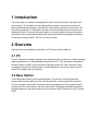
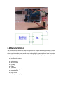
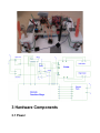
2.2 Remote Station
The remote station is where the meat of the project lies. Most of the development time is spent
on the remote station as it contains the actual motors and all the sensors. A dismantled hard
drive is used to provide a very smooth freely rotating disk. A square styrofoam base is mounted
on top of the exposed disk and secured with cable ties. The following components are placed on
top of the styrofoam base:
● two fans with motors
● two sonar sensors
● wireless radio
● Arduino board
● H-bridge
● Relay
● Transistor
● three voltage regulators
● manual switch
● logic circuits
● battery power supply
It is very important to balance the platform. If the platform is unbalanced the platform does
not align with the wall easily. One difficulty came from an unbalanced platform settling in an
unaligned position which forced the motors to realign the platform continuously. To avoid this
difficulty it is suggested to plan the layout of each component on top of the platform ahead
of time. Test the balance by holding the bottom of the hard drive casing while the platform is
spinning.
3 Hardware Components
3.1 Power
The remote station is powered by one 7V battery. Components are isolated from each other
using voltage regulators. Not isolating the components can lead to unexpected transient bugs
as components can interfere with each other. This is particularly true with the motors which
have a large power spike when starting up. Power to the motors is regulated with the L298
H-bridge. Everything else is regulated through three 7805 voltage regulators. A kill switch
provides emergency motor stop functionality. A manual switch controls power to all parts of the
circuit.
3.1.1 Power Supply
Power to certain components, especially motors, is supplied from a source external to the
Arduino board to prevent the voltage on the board dropping and causing a reset or other
unexpected behavior. The remote station is powered by the batteries that were provided in the
lab and the base station is powered by USB from the PC. Early experiments on the remote
station used an AC adapter which converts wall power to 12v DC at 400mA (measured at about
17v). All power is regulated to 5v by an L298 for the motors and a 7805 for other components.
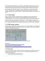
3.1.2 7805 Voltage regulator
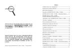
Following simple instructions we managed to install a 7805 voltage regulator on our breadboard.
Regulated voltage measures at exactly 5.00 volts on the multi meter. 1µF and 0.1µF capacitors
are used in the following configuration.
Devices such as sonars can be connected from “5v out” to the ground.
References:
http://www.tkk.fi/Misc/Electronics/circuits/psu_5v.html
How capacitors work (identifying the polarity)
http://www.tubelab.com/AssemblyManualSimpleSE/Capacitors_SSE.htm
3.1.3 Kill switch
A kill switch provides the ability to shut down the motors though user input. The switch consists
of a mechanical relay, transistor, resistor, and diode. Some high level explanations of relay
switches are available here:
● www.autoshop101.com/forms/hweb2.pdf
●
http://electronics.howstuffworks.com/relay1.htm
3.1.3.1 SRD-5-105D Mechanical Relay
A relay electrically separates two circuits. This is used to separate a low power control circuit
from the high power motor circuit. The relay is a very simple device. Their are five pins on the
relay, two pins for the control circuit and three for the controlled circuit. On the control side
there is one pin on each side of a solenoid. On the other side there is one ground, one normally
closed (NC), and one normally open (NO) pin. When no current is passing through the solenoid
the NC pin is short to ground. When current is passing through the solenoid the NO pin is short
to ground.
3.1.3.2 CT 2N3904 Transistor
A transistor is used in the control circuit to switch current through the solenoid on and off. The
collector is connected to one of the solenoid pins, the emitter is connected to common ground,
and the base is driven by an I/O pin on the Seeeduino. When the I/O pin is high the transistor
allows current to flow through the solenoid. This creates a magnetic field in the solenoid causing
the mechanical switch to flip from NC position to NO position. An alternative method for driving
the control circuit is to remove the transistor and drive the relay Vcc directly with the I/O pin.
While this is possible the amount of current used to drive the base is much less than the current
required through the solenoid to trigger the relay switch. Where Ic is the collector current and
Ib is the base current and hef is the transistor gain Ic = Ib*hef which means the current used
driving the base is a factor hef less than current through the solenoid. Since the Seeeduino has
limited total current output it is best to use a transistor and use the battery to provide the current
for the solenoid itself. In our case the base current is only 2.44mA compared to a solenoid
current of over 40mA to activate the switch.
3.1.3.3 Diode
A small diode is used to help dissipate the current spike after the magnetic field of the solenoid
collapses. This prevents damage to the transistor.
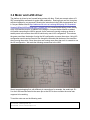
3.2 Motor and L298 driver
The platform is driven by two forward facing motors with fans. Each one accepts values of 0255 in analogWrite commands for pulse width modulation. Running them one at a time gives
sufficient impulse for our purposes.Following the instructions in the L298 documentation and
in Conyers-Walker-Warick http://webhome.csc.uvic.ca/~mcheng/466/spring.2011/handouts/
Sample%20Past%20Projects/project1_awalker.pdf), we connected the battery power directly
to the L298 and the motors. In addition to the design in Conyers-Walker-Warick we added
a kill switch connecting the L298 to ground. As the motors are usually running we chose to
enable power to the motors when the kill switch relay was in NC configuration. This reduces
the power used from the design of using the NO configuration to power the motors. Using NO
configuration would require current to flow though the solenoid and the base of the transistor
when running the motors. Since the motors are running more often than not it is a waste to use
the NO configuration. We made the following connections to the L298.
We did some debugging first, with different pin connections; for example, the enable pin, E12 on the L298 was connected to the same pin as the LED to show us when the motor was
supposed to be working.
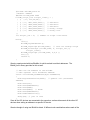
To test the motor we ran the following code:
#include "WProgram.h"
#include "avr/interrupt.h"
extern "C" void __cxa_pure_virtual(){
cli();
// disable interrupts
for(;;); // do nothing until hard reset
}
int pinEnable1_2 = 13;
int pinI1 = 12;
int pinI2 = 11;
void setup(){
pinMode(pinEnable1_2, OUTPUT);
pinMode(pinI1, OUTPUT);
pinMode(pinI2, OUTPUT);
}
void loop(){
//run at low speed in one direction for a time
analogWrite(pinEnable1_2,40);
digitalWrite(pinI1,HIGH);
digitalWrite(pinI2,LOW);
delay(3000);
//other direction
digitalWrite(pinI1,LOW);
digitalWrite(pinI2,HIGH);
delay(3000);
//stop
analogWrite(pinEnable1_2,0);
delay(3000);
}
int main(void){
init();
setup();
for (;;)
loop();
return 0;
}
3.2.1 Pulse Width Modulation (PWM)
Pulse width modulation is a technique to control the power to inertial electrical devices. We
have to send the signal to a device (in our case, the motor) as a square wave. Then we have to
control the width of the square pulse.
A PWM signal is a square wave that occupies a certain percentage of the period with a high
signal. This percentage is called the duty cycle, and it regulates the power output of a given
pin. The output pins with PWM control are marked on the Arduino boards, and we used these
to regulate power to the motor enable pin on the L298, using the command analogWrite().
Instructions for this function are at http://arduino.cc/en/Tutorial/PWM.
If the period of the PWM is in the audible range of frequencies, the motors will whine. We
changed the period by accessing the PWM registers, as per the Lab TA’s instructions.
3.3 Two Sonars, One Pin, and a Special Wall
Two forward facing sonars are triggered independently and their signals are read with a
hardware interrupt pin and timer register on the micro chip. When we chose the Seedstudio
Ultrasonic Sensor (SUS) over the MaxSonar EZ1 (MSE), we thought our project would incur
both an improvement in accuracy and in simplicity. Ironically, however, the SUS’s single signal
pin proved to be much more headache than was intended.
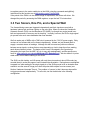
We first used a pair of MSEs with a 7085 circuit, powered by the 7.2V DC power supply. Early
versions of our software did not fire these independently; instead, we just allowed them to
supply a constant stream of readings. Although this did not cause any obvious collisions
between sonar signals, we knew that we were depending on luck to keep them from reading
each others ultrasonic pulses. The basics of this circuit is illustrated in the figure below.
Interpreting the input from the MSE “An” pin is easy with analogRead(), and the specifics are
found in www.maxbotix.com/uploads/MaxSonar-EZ1-Datasheet.pdf. We also tested it in pulse
width mode, but not before starting on the SUSs.
The SUS is a slick looking, red US sensor with only three pins and only about 250 words (we
counted them) in under two pages of well illustrated documentation. Having been oversimplified
to appeal to a wider audience, the single signal pin of the SUSs proved to be an obstacle when
wanted to use the same ATmega pin to time the pulse width outputs from two sonars (see
Section, Hardware Interrupts Timers). The problem, of course, is that it becomes impossible
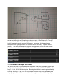
to trigger each sonar independently. To solve this, we first tried diodes in the following
configuration:
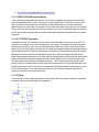
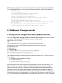
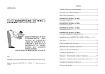
We ran into troubles with diodes. The most interesting one was that some of them allowed a
2µS back pulse that would sometimes trigger the other sonar. Here is the logic analyser output
showing that. Channel 5 and 6 are the trigger outputs from the micro controller and Channel
7 is the input pin ICP1. We can see that Channel 6 was given a deliberate 10µS pulse, from
the Seeedstudio specifications, and then we can see that return pulse from the sonar. Channel
7 shows the same thing because of the orientation of the diode, but Channel 5 should show
nothing. Instead it shows tiny, 2µS pulses at each rising edge from Channel 6. Sometimes this
fires the sonar, sometimes it does not.
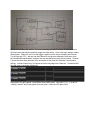
We used an OR gate instead, created from three NAND gates. Note that P | Q = ~(~(P&P) &
~(Q&Q)), where P and Q are signals from the sonar. Here is the OR gate circuit.
We used the logic analyzer again to verify that the sonars wire signals were not interferering
and that the interrupt pin was interpreting the pulses correctly. Here, Channels 5,6,7 are the
same as before, but Channel 4 is an output pin that is set high whenever the micro controller
thinks it is measuring a pulse returning from a sonar. Once again, the trigger pulse and
subsequent return high signal is seen in Channels 5 and 6 individually. They are ORed to
Channel 7. The micro controller knows to ignore the trigger pulse, so only the return signals
from each sonar are shown on Channel 4.
3.3.1 Hardware Interrupts and Timers
The Arduino Uno with the ATmega328p micro chip has a 16-bit timer, accessible through output
pin 8 (pin 14 on the chip). This timer can be set to increment, from 0x0000 to 0xFFFF, once
every 1, 2, 8, 64, 256 or 1024 clock cycles. By setting the right bits in certain registers, the chip
will accept “interrupts” on pin 14, in the form of either a voltage drop or rise (called falling and
rising edges), at which point, the contents of the timer register are copied into the input capture
register (ICR1). The interrupt can also trigger a software routine, so that ICR1 can be used
immediately.
These registers and the bits that can be set are very carefully described in the long, 566
page version of the atmega328p specifcations at http://www.atmel.com/dyn/resources/
prod_documents/doc8271.pdf, so we will focus on how to find the relevant information in
that document (a summary of this document is at http://www.atmel.com/dyn/resources/
prod_documents/8271S.pdf). The related specifications of for the Seeeduino’s processor are
available from the same website.
The registers relevant to the 16-bit timer are as follows:
● TCNC1. This is a 16-bit timer register.
● TCCR1B: Timer/Counter Control Register B. This register has flag-bits which determine
the behaviour of the Timer and Input Capture behaviour. These bits are named as
follows:
○ ICNC1: Input capture noise canceller. This measures the voltage input at pin 14
on four consecutive clock cycles to ensure that a detected edge is not noise. It is
not always necessary to set this (to 1).
○ ICES1: When this is set to 1, an interrupt is triggered on a rising edge, and
otherwise on a falling edge.
○ CS12, CS11, CS10: These bits control the frequency with which the timer,
TCNC1 is incremented (prescaling).
● TCCR1A: We set this to 0 to override an initialization by the Arduino library which uses
this timer for PWM.
● ICR1: This is the register to which TCNC1 is copied to when an interrupt is signalled.
● TIMSK1: Timer/Counter1 Interrupt Mask Register. Setting the ICIE1 bit to 1 enables
interrupt capture for timer 1.
This configuration works as follows for the Arduino Uno. On the ATmega328p, ICP1 pin is
called PB0 (14), which is connected to output pin 8 of the Arduino Uno. On the Seeeduino
Mega, ICP1 is available, but not as an Arduino Mega pin. Instead, there is a direct connection
to it, at PD4. PD4 is an input pin by default, but in case it needs to be accessed, it’s mode can
be set with
//set PD4 pin to input.
DDRD &= ~_BV(4);
//set PD4 pin to low
//PORTD &= ~_BV(4);
//set PD4 pin to high
//PORTD |= _BV(4);
Last but not least, the following should be included for these things to work.
#include <avr/io.h>
#include <avr/interrupt.h>
3.3.1.1 Alternative Approach: Using pulseIn()
The Arduino library function, pulseIn, purports to wait for a HIGH or LOW pulse on a given pin
and return the length of pulse in microseconds. It does do this, but it freewheels the Arduino’s
CPU, putting all other tasks on hold, from when the function is called, until the pulse is complete
(or it times out). pulseIn(pin,HIGH) runs a loop to wait for the pin to go low, then another to wait
for it to go HIGH again, and a third to measure the amount of time it is HIGH for (and waits for
a low). It measures this time by counting the iterations of the last loop and multiplying it by the
cycles per loop.
Suppose an interrupt was encountered during pulseIn, then the measurement would not
account for the clock cycles used during the interrupt, because the loop of pulseIn would not
iterate during that time. Furthermore, if an edge was encountered during the interrupt, then
pulseIn would not know when it happened.
Alejandro made a forum post about it at
http://arduino.cc/forum/index.php/topic,51632.msg371213.html#msg371213
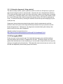
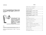
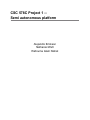
3.3.2 Corrugated Wall
Finally, we come to the accordion wall. We found that the sonars gave unreliable readings
when the platform was more than 15 degrees from the wall. The sonar’s range is so much
greater than the distances we were measuring, so we were able to disperse the return signal by
making a corrugated wall, pictured below. This helped the sonars enormously (so much so, that
the idea was adopted by several other groups in the class).
http://www.adafruit.com/blog/2009/06/23/getting-started-with-the-maxbotix-sonar-sensor-quickstart-guide/
http://www.instructables.com/id/Getting-started-with-the-Maxbotix-sonar-sensor-q/
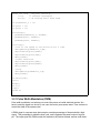
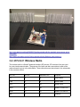
3.4 nRF24L01 Wireless Radio
The wireless radio is a Serial Peripheral Interface (SPI) device. SPI consists of six pins used
for control and communication. The purpose of the pins and their connections to each of the
arduino boards is given in the table below. These connections are also shown in the schematics
in the overview section
SPI Pins
Uno Pin
Seeeduino Pin
Purpose
CE
8
8
Chip Enable
CSN
9
9
Slave Select
SCK
13
52
Serial Clock
MISO
12
50
Master In Slave Out
MOSI
11
51
Master Out Slave In
IRQ
2
2
Interrupt
The CE, CSN, and IRQ pins can be changed but the SCK, MISO, MOSI pins must be
connected to the indicated pins for SPI to work correctly. For more information check Neil’s
guide at http://nrqm.ca/mechatronics-lab-guide/lab-guide-using-the-radio/ or the Arduino board
data sheet. Reading the data sheet explains SPI timings but Neil’s guide is excellent for getting
started.
3.5 Unfinished components
3.5.1 BlinkM LED and I2C
Due to time contraints, we were unable to add BlinkM LEDs to our project. Instead, we made
them work with a separate Arduino. The BlinkMs are I2C devices, meaning that each one
has an address. By giving each I2C device a unique address, we are able to control many of
them on the same two I2C pins of the Arduino board. Roughly speaking, the micro-controller
broadcasts instructions for an I2C device with a certain address. All the I2C devices receive
those instructions, but they are only carried out by the one with the correct address.
Taking hints from Conyers et al., we found that the Arduino has I2C pins and that the Wire.h
library is used to communicate with I2C devices. Furthermore, there is a library for the BlinkM
LED that wraps the Wire.h libary with nice commands. The links we followed are given below:
●
●
●
●
●
●
Conyers et al. http://webhome.csc.uvic.ca/~mcheng/466/spring.2011/handouts/
Sample%20Past%20Projects/project1_awalker.pdf
Finding the I2C pins on the Arduino Uno - http://arduino.cc/en/Main/ArduinoBoardUno
About the Wire.h library - http://arduino.cc/en/Reference/Wire
Examples using the BlinkM LED library - http://todbot.com/blinkm/example_code/
Datasheet and resources for the BlinkMLED - http://thingm.com/products/blinkm.html
About libraries. Helps understand how compilers use the libraries. - http://arduino.cc/en/
Hacking/LibraryTutorial
The datasheet (above) has detailed instructions on how to script the BlinkMs. This means a list
of instructions can be sent which will be executed in sequence by the LED. See the Appendix
for example code. Here is a command shown in the datasheet.
{‘n’, 0xff,0xff,0xff} // set full on (bright white) now
The example code at thingm.com uses a file called BlinkM_funcs.h, which is a library that
uses the functions in Wire.h. Note that BlinkM_funcs.h contains code which should be moved
to a .cpp file before used in a project of any significant size. Here is a snippet that plays a
hardcoded script.
#include "WProgram.h"
#include "Wire.h"
#include "BlinkM_funcs.h"
//default address
#define blinkm_addr 0x00
blinkm_script_line script1_lines[]
{ 1, {'f', 255,00,00}},
{ 1, {'c', 0x21,0x22,0x23}}, //
{ 1, {'h', 0x00,0x00,0x00}}, //
{ 1, {'c', 0x61,0x62,0x63}}, //
{ 1, {'c', 0xfd,0xfd,0x01}}, //
{ 1, {'c', 0x02,0xfe,0xfe}}, //
};
int script1_len = 6; // number of
= {
dim white
dim white
dim white
mostly orange
mostly teal
script lines above
main(){
init();
BlinkM_beginWithPower();
BlinkM_stopScript(blinkm_addr); // turn off startup script
BlinkM_writeScript( blinkm_addr, 0, script1_len, 0,
script1_lines);
BlinkM_playScript( blinkm_addr, 0,0,0 );
for(;;);
return 0;
}
We also experimented with two BlinkMs, for which we had to set their addresses. The
BlinkM_func.h library provides for this as well:
// Sets the I2C address of the BlinkM.
// Uses "general call" broadcast address
static void BlinkM_setAddress(byte newaddress)
{
Wire.beginTransmission(0x00); // general call (broadcast
address)
Wire.send('A');
Wire.send(newaddress);
Wire.send(0xD0);
Wire.send(0x0D); // dood!
Wire.send(newaddress);
Wire.endTransmission();
delay(50); // just in case
}
Since all the I2C devices are connected to the same bus, we have disconnect all the other I2C
devices when setting an address to a specific I2C device.
We also thought of using two BlinkM to obtain 16 different color combinations where each of the
BlinkM would be assigned one of the four colors (white, red, green, blue) easily distinguishable.
Our modified BlinkM library for this included the following functions, detailed in the Appendix:
//set up I2C
void BlinkM_begin();
//for setting the address of each device
void BlinkM_setAddress(byte addr);
//used in SetoneBlink and twoBlinks
void BlinkM_SetColor(byte red, byte green, byte blue);
//set BlinkM at addr to color
void BlinkM_SetoneBlink(byte addr,int color);
void BlinkM_SetColor_twoBlinks(byte addr1,byte addr2,int color1,
int color2);
//a quick script on the microcontroller using SetonBlink
void BlinkM_startUpScript(byte addr1, byte addr2);
4 Software Components
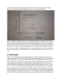
4.1 Proportinal Integral Derivative (PID) Controller
We used a Proportional–Integral–Derivative controller (PID controller) to control the speed
of our motor. The output of our PID controller is more or less as follows:
u(t)= Kp*e(t) + Ki*Iout + Kd*Dout
Here,
u(t)= the output at time t, in our case this is the output speed of our motor.
e(t)=error at time t, which is the difference between the two sonars in our case.
Kp= proportional gain
Ki=integral gain
Kd= differential gain
Iout = integral output, the sum of all the errors from the beginning.
Dout = differential output, the rate of change of errors.
The variables affecting the autonomous control extended beyond the PID. They were more or
less as follows:
● Pre-filter for sonar readings to PID input
● PID update frequency
● Post-filter for PID output to motor input
We found that our desire to have frequent PID updates was in conflict with three things. The
first two concern Dout . The first is that a motor must be turned on for a minimum of about
500ms to give a useful impulse. The second is that the platform rarely rotates through more
than about a 1cm arc per 100mS (at the position of the sonars), so the value of Kd does not
accurately reflect the speed at which the platform is rotating. Suppose the PID is updated every
100ms and the error term has increased by 1 for 500ms, then the derivative value of the PID is
Kd*1 for each reading. We modified the PID to increase the memory of Dout , so that it compares
error terms that are five readings apart, rather than one. This helped give a greater, longer
impulse when the platform has rotated away from the wall for several readings.
Finally, we wanted to avoid having and I value that integrates over an infinite number of error
terms. Instead, we saved 50 error terms in a buffer which updates in constant time. The same
buffer is used to access the 5th last error term to compute the above Dout term. We found that
50 values causes too much overshoot, however. One solution we are discussing is reducing 50
to around 10, or maybe using an exponential decay for the integral output instead of summing
up all errors in an array. Implementing the latter is simple: Instead of Iout=Iout+e(t), we would use
Iout=c*Iout+e(t) where 0<c<1. Therefore, at time t + k, the weight of e(t) in the sum, Iout is (c^k)
e(t).
4.2 Gamepad
Python code to read data from the USB gamepad on a windows machine was provided. The
program was written by River Allen and although it has some threading issues it works fairly well
without modification. User input consists of twelve buttons, a directional pad, and two analog
sticks. Each of the twelve buttons is represented by a byte, which greater than zero if the button
is pressed and zero otherwise. The directional pad is represented as two bytes, one byte for
up/down and one for left/right. Each of these bytes has three status values, up/right = 1, down/
left = -1, neutral = 0. Pressing up and right would result in two bytes both set to 1. The analog
sticks are represented by two bytes each. One byte for up/down, one for right/left, similar to the
directional pad. Each byte ranges from -100 to 100 depending on how far the stick is pressed in
any given direction. This results in a total of 12 + 2 + 4 = 18 bytes of data when reading the user
input. The number of bytes used can be reduced significantly by using a bit vector to represent
the buttons and directional pad. Reducing the bytes down to 6 bytes is a trivial exercise. Despite
the ability to reduce the bytes down to 6 this change was implemented and then removed.
The reason this feature required changes in the base station and remote station with little
actual benefit in this current phase. The radio sends packets larger than 18 bytes anyway and
therefore the only communication that is reduced is on the serial port. Since the data updates
from the gamepad have a short delay leaving the original design has negligable performance
degredation.
After reading input from the gamepad the program forwards the input to the base station over
the serial UART connection. We encountered an error where the bytes read by the base station
were a shifted version of what was expected to be received from the PC. Initially we attempted
to flush the serial connection before initializing transfer however this did not fix the error. A
simple work around for the problem is adding a flag byte to the begining of the bytes sent to the
base station. It is essential that the flag byte value never occurs in any of the actual data bytes
that are sent. Since the analog sticks have the largest range (-100,100) any value outside of this
is a valid flag byte. When the base station reads a flag byte it knows it is synchronized with the
bytes and the input can be passed to the remote station.
4.3 Utilities
Initially manual tuning of remote station PID settings required changing the hard coded settings,
recompiling the source and uploading to the Arduino board. This is a very time consuming
process and the settings must be tweaked constantly while finding values that perform well. To
make matters worse if the environment the remote station is operating in changes or the weight
is added to the platform previously good values can become useless. Looking ahead to the
remaining phases of the project we decided that taking time to develop some helpful utilities in
phase one will save countless hours later.
Using Python and TkInter we created a simple GUI terminal that is able to echo serial port data
and live update the PID settings using the keyboard. This interface allows our team to quickly
adjust PID settings while the platform is powered on making finding the critical values much
easier. Each time the settings are updated the PID calculation is reset and started fresh to avoid
pollution from the previous error terms.
The real advantage of this terminal is continued development as the term progresses. Adding
features to remotely modify and debug the remote station will prove invaluable. A major feature
that is planned for project phase two is a live sensor data and PID error term plotter. The plotter
will graph and perform analysis on the actual sensor and control data live. This gives our team
much more precision than eyeballing what is occurring at the remote station or even using flat
text to calculate oscillation periods. Phase 3 plans include using the software to tune the PID
automatically with no user input.
4.5 Wireless Radio
A driver and example code for the wireless radio is provided by Neil’s lab guide. This code
is very clean and easy to understand. The main task is to design what communication the
base station and remote station need to handle. Clearly commands from user input using
the gamepad or utilities need to be passed to the remote station over the radio. It is useful
to have debugging information to flow from the remote station to the base station. Wireless
networking is particularly prone to data errors which must be handled in software. The radio
provides automatic retransmission attempts and an auto ack feature. Even if the auto ack is
received this does not gaurentee that data has not been lost. To handle this a simple master
slave configuration with application level acknowledgements is suggested. In our current phase
the need for reliability is not high and therefore we decided to handle lost transmissions by
repeating a command or just missing a data debug message. This granularity was sufficient
for this project. Future projects will need a more robust system with reliability built into our
communication.
The radio driver is straight forward to use. Here is a code snippet to get the radio going.
void setup() {
pinMode(RADIO_VCC, OUTPUT);
digitalWrite(RADIO_VCC, HIGH);
Radio_Init();
Radio_Configure_Rx(RADIO_PIPE_0, host_addr, ENABLE);
Radio_Configure(RADIO_2MBPS, RADIO_HIGHEST_POWER)
Radio_Set_Tx_Addr(DEST_ADDR);
delay(250);
}
It is important to define an I/O pin for the radio Vcc. This allows reseting the radio in software.
Without this the radio can get stuck when the board is reset but the radio isn’t as the receive
buffer can be full and block sending any packets. Also this is very useful for handling radio
errors. One thing to be careful about is race conditions for the receive buffer. This next snippet
shows a potential fatal flaw for the radio.
if( Radio_Receive(&in_packet) != RADIO_RX_MORE_PACKETS){
rxflag = 0;
}
This code was used on the provided debug server. Looking closely however reveals that if an
interrupt from the radio receiving a packet comes right before setting rxflag to 0 the software will
never go receive the packet which in turn kills the radio as the buffer is waiting to be received
from. The only remaining changes are to add packet types to the radio.h file and everything
flows smoothly.
Misunderstandings regarding the supplied radio code cost more hours than was spent actually
coding the modifications after the misunderstanding was cleared up. There are two versions of
the code currently available. The USB drive at the front of the class does not contain the current
version. This caused hours of fixing the drivers provided from the USB drive. The following day
Neil clarified that the USB drive had not been updated and we threw out our changes switching
to the new version supplied online. The cost from this mistake continued when the familiarity
with the initial code caused us to miss the define statement that was used to switch between the
Seeeduino and UNO configurations. With the software configuration still set to UNO the code
was uploaded to the Seeeduino with of course the wrong pins being used. The logic analyzer
showed that the SPI signals were not correct but it still took a long time to find out why. Another
time consuming error was caused by losing connectivity through the hardware by wires breaking
loose inside of the soldered headers. This can be generally indicated by radioInit() failing to
return. Verify the problem using a multimeter before looking for software errrors.
5 Lab Environment
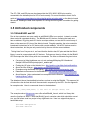
5.1 Eclipse Software
Eclipse seems to be the IDE of choice for the avr toolchain for most Arduino programmers.
Step by step tutorials for the project settings and installation are available at:
Neil’s lab guide
http://nrqm.ca/mechatronics-lab-guide/lab-guide-software-environment/
The Arduino playground
http://www.arduino.cc/playground/Code/Eclipse
Some better instructions for Mac OS X
http://robertcarlsen.net/2009/10/31/arduino-in-eclipse-989
Eclipse can be frustrating to first-time users, so we also used GNUmake.
See Section “Eclipsed by GNUmake” for an alternative.
5.2 Eclipsed by GNUmake
Eclipse is used in this course because it gives more control over source code and libraries
than the Arduino IDE does, however, it carries several disadvantages. Written in Java, it does
not run natively and hence, feels foreign on most machines. The instructions for configuring
the avr toolchain on Eclipse require about ten different steps and nearly as many menus and
windows. Troubleshooting the configuration is cumbersome because each page in the project
properties must be viewed separately and one cannot compare the properties of two projects
without leaving the properties window and switching to that of the other project. It is much more
efficient, and a more useful skill, to use GNUmake.
GNUmake intelligently interprets a special script for compiling projects in any language that
can be compiled from the terminal, and has been doing so since 1989. Learning GNUmake
for this class will serve us in other projects relevant to our research much more than Eclipse
can. Furthermore, the entire compilation procedure is visible at one time and a makefile can be
copied from project to project without any difficulty. Finally, the editing of files can be done in
our favourite source code editors, rather than Eclipse (which, for one thing, does not understand
Vim or Emacs commands).
We found a few makefiles for arduino and the avr toolchain on the Internet, but they all
needed some modification which required an understanding of how a makefile is written. The
GNUmake documentation at http://www.gnu.org/software/make/manual/make.html is well
written, and the first few chapters help understanding the basic elements of the makefile. For
example, a command looks like this.
target ... : prerequisites ...
recipe
...
...
The target is an output file, built from the prerequisites, using the command line command in the
recipe. Typically, these three elements are written with variables. For example,
# Compile: create object files from C++ source files.
.cpp.o:
$(CXX) -c $(ALL_CXXFLAGS) $< -o $@
Here, the first line is a comment and anything of the form $(*) is a variable, defined somewhere
in the makefile. The two strings $< and $@ are automatic variables, input and output. This
recipe essentially tells the terminal to compile $< with the C++ compiler chosen in $(CXX) and
output to the file $@ with flags defined in $(ALL_CXXFLAGS) as well as -c.
The Arduino IDE is updated frequently, and the newest makefiles we found referred to the file
structure in version 0017 and 0018. Furthermore, not all makefiles are made for Mac OSX.
These are the major makefile projects we found:
-From the arduino site and quite out of date. Several makefiles were stems of this one
http://www.arduino.cc/en/uploads/Hacking/Makefile
-Two independent projects.
http://mjo.tc/atelier/2009/02/arduino-cli.html
http://bleaklow.com/2010/06/04/a_makefile_for_arduino_sketches.html
-A github project that we found nearly by accident.
http://blog.codekills.net/archives/71-Makefile-for-Arduino-0017.html
https://gist.github.com/273821
-A makefile for windows under cygwin
http://www.tinymicros.com/wiki/Makefile_For_Arduino_Under_Cygwin/Windows
-About the AVR Toolchain
http://www.nongnu.org/avr-libc/user-manual/index.html
-Some explanation about libraries and archives
http://heather.cs.ucdavis.edu/~matloff/UnixAndC/CLanguage/Make.html#tth_sEc4
-More explanation about compiling arduino from the command line
http://www.sjbaker.org/wiki/index.php?title=Command_line_Arduino
-Very granular explanation about the Arduino build process
http://arduino.cc/en/Hacking/BuildProcess
A cmakefile was also provided to us privately by Paul Reimer. It helped our understanding of
makefiles, however we did not have the cmake variant of make installed.
None of these worked perfectly, so we wrote our own makefile from scratch. First to familiarize
ourselves with make, but also to eliminate complications like support for assembly and listing
files, present in the above files. Finally, we needed to ensure that external libraries were being
compiled correctly.
See the Appendix for our current makefile and commentary within it. We expect to make some
changes to this over the course of the semester.
5.3 Some errors
Here are a few errors and solutions.
When compiling
error: MCU "atmega328p" supported for assembler only
This appeared because we were using avr-gcc version 3.* and should have been using 4.*.
Run the command
$ avr-gcc --version
in a Mac OSX terminal to see the version and run
$ avr-gcc-select 4
to select the 4.* version.
Reference: http://www.pololu.com/docs/0J31/all
In the makefile
Makefile:149: *** missing separator. Stop.
make requires tabs in front of recipes, but some programs replace tabs with spaces. If this
happens, do a find and replace to go from 4 spaces (or 8, or whatever the number is you find in
front of the recipes) to tabs.
Output from compilation
… error: WProgram.h: No such file or directory
… error: Wire.h: No such file or directory
These will be followed by a string of errors every time you use something defined in those
header files and it means your compiler is not finding the appropriate libraries. Make sure that
you have -I(path to library) for each of these in the makefile.
5.4 Collaboration Tools
Our team relied on Apache Subversion (svn) for version control and source code sharing. For
the uninitiated, source code and other resources under version control is kept in an online
database, called a repository. We request what is called a “working version” of whichever
portion of the repository we would like. We may make changes and upload them, or update our
working versions from the repository. Local software, called an svn client, tells us the state of
repository, with respect to our working version.
When looking for a good svn tutorial, google is your friend. For Mac OS X, a very good svn
client is called “Versions” (free trial). Finally, we used assembla.com to host our repository.