1
User’s
Manual
Model EJA438W and EJA438N
Diaphragm Sealed Gauge
Pressure Transmitters
[Style: S2]
IM 01C22J01-01E
IM 01C22J01-01E
18th Edition
i
Model EJA438W and EJA438N
Diaphragm Sealed Gauge Pressure Transmitters
[Style: S2]
IM 01C22J01-01E 18th Edition
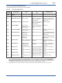
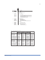
Contents
1.
Introduction................................................................................................ 1-1
Regarding This Manual................................................................................................. 1-1
2.
1.1
For Safe Use of Product ................................................................................... 1-2
1.2
Warranty.............................................................................................................. 1-3
1.3
ATEX Documentation........................................................................................ 1-4
Handling Cautions..................................................................................... 2-1
2.1
Model and Specifications Check...................................................................... 2-1
2.2
Unpacking........................................................................................................... 2-1
2.3
Storage................................................................................................................ 2-1
2.4
Selecting the Installation Location ................................................................. 2-1
2.5
Pressure Connection......................................................................................... 2-2
2.6
Waterproofing of Cable Conduit Connections............................................... 2-2
2.7
Restrictions on Use of Radio Transceiver...................................................... 2-2
2.8
Insulation Resistance and Dielectric Strength Test....................................... 2-2
2.9
Installation of Explosion Protected Type........................................................ 2-3
2.9.1
FM Approval........................................................................................ 2-3
2.9.2
CSA Certification................................................................................. 2-5
2.9.3
IECEx Certification.............................................................................. 2-7
2.9.4
ATEX Certification............................................................................... 2-8
2.9.5
TIIS Certification............................................................................... 2-10
2.10
EMC Conformity Standards............................................................................ 2-12
2.11
PED (Pressure Equipment Directive)............................................................ 2-12
2.12
Low Voltage Directive...................................................................................... 2-12
3.
Component Names................................................................................... 3-1
4.
Installation.................................................................................................. 4-1
4.1
Precautions ....................................................................................................... 4-1
4.2
Mounting the Diaphragm Seals ....................................................................... 4-1
4.3
Transmitter Mounting........................................................................................ 4-2
4.4
Affixing the Teflon Film..................................................................................... 4-3
4.5
Rotating Transmitter Section............................................................................ 4-3
4.6
Changing the Direction of Integral Indicator ................................................. 4-4
18th Edition: July 2015 (KP)
All Rights Reserved, Copyright © 1995, Yokogawa Electric Corporation
IM 01C22J01-01E
ii
5.
Wiring.......................................................................................................... 5-1
5.1
Wiring Precautions............................................................................................ 5-1
5.2
Selecting the Wiring Materials.......................................................................... 5-1
5.3
Connections of External Wiring to Terminal Box........................................... 5-1
5.4
6.
7.
5.3.1
Power Supply Wiring Connection....................................................... 5-1
5.3.2
External Indicator Connection............................................................ 5-1
5.3.3
BRAIN TERMINAL BT200 Connection.............................................. 5-2
5.3.4
Check Meter Connection.................................................................... 5-2
Wiring.................................................................................................................. 5-2
5.4.1
Loop Configuration............................................................................. 5-2
5.4.2
Wiring Installation................................................................................ 5-3
5.5
Grounding........................................................................................................... 5-4
5.6
Power Supply Voltage and Load Resistance.................................................. 5-4
Operation.................................................................................................... 6-1
6.1
Preparation for Starting Operation.................................................................. 6-1
6.2
Zero Point Adjustment...................................................................................... 6-2
6.2.1
When you can obtain Low Range Value from actual measured
value of 0% (0 kPa, atmospheric pressure);....................................... 6-2
6.2.2
When you cannot obtain Low Range Value from actual measured
value of 0%;........................................................................................ 6-3
6.3
Starting Operation............................................................................................. 6-3
6.4
Shutting Down Operation................................................................................. 6-3
6.5
Setting the Range Using the Range-setting Switch....................................... 6-4
BRAIN TERMINAL BT200 Operation....................................................... 7-1
7.1
7.2
7.3
BT200 Operation Precautions.......................................................................... 7-1
7.1.1
Connecting the BT200........................................................................ 7-1
7.1.2
Conditions of Communication Line..................................................... 7-1
BT200 Operating Procedures........................................................................... 7-2
7.2.1
Key Layout and Screen Display.......................................................... 7-2
7.2.2
Operating Key Functions.................................................................... 7-2
7.2.3
Calling Up Menu Addresses Using the Operating Keys..................... 7-4
Setting Parameters Using the BT200............................................................... 7-5
7.3.1
Parameter Summary.......................................................................... 7-5
7.3.2
Parameter Usage and Selection......................................................... 7-8
7.3.3
Setting Parameters............................................................................. 7-9
(1) Tag No. Setup .................................................................................... 7-9
(2) Calibration Range Setup..................................................................... 7-9
(3) Damping Time Constant Setup . ...................................................... 7-10
(4) Output Signal Low Cut Mode Setup ................................................ 7-11
(5) Change Output Limits ...................................................................... 7-11
(6) Integral Indicator Scale Setup........................................................... 7-11
(7) Unit Setup for Displayed Temperature . ........................................... 7-13
IM 01C22J01-01E
iii
(8) Operation Mode Setup . ................................................................... 7-13
(9) Output Status Display/Setup when a CPU Failure .......................... 7-13
(10) Output Status Setup when a Hardware Error Occurs ..................... 7-14
(11) Range Change while Applying Actual Inputs ................................... 7-14
(12) Zero Point Adjustment ..................................................................... 7-15
(13) Span Adjustment............................................................................... 7-16
(14) Test Output Setup ............................................................................ 7-17
(15) Ambient temperature zero shift compensation................................. 7-17
(16) User Memo Fields............................................................................. 7-18
7.4
7.5
8.
7.4.1
Displaying Measured Data............................................................... 7-19
7.4.2
Display Transmitter Model and Specifications.................................. 7-19
Self-Diagnostics............................................................................................... 7-19
7.5.1
Checking for Problems..................................................................... 7-19
7.5.2
Errors and Countermeasures........................................................... 7-21
Maintenance............................................................................................... 8-1
8.1
Overview............................................................................................................. 8-1
8.2
Calibration Instruments Selection................................................................... 8-1
8.3
Calibration.......................................................................................................... 8-1
8.4
Disassembly and Reassembly......................................................................... 8-3
8.5
9.
Displaying Data Using the BT200................................................................... 7-19
8.4.1
Replacing the Integral Indicator.......................................................... 8-3
8.4.2
Replacing the CPU Board Assembly.................................................. 8-4
Troubleshooting................................................................................................. 8-4
8.5.1
Basic Troubleshooting........................................................................ 8-5
8.5.2
Troubleshooting Flow Charts.............................................................. 8-5
General Specifications............................................................................. 9-1
9.1
Standard Specifications.................................................................................... 9-1
9.2
Model and Suffix Codes.................................................................................... 9-4
9.3
Optional Specifications..................................................................................... 9-6
9.4
Dimensions......................................................................................................... 9-9
Installation and Operating Precautions for TIIS Intrinsically Safe Equipment
........................................................................................................... EX-A03E
Installation and Operating Precautions for TIIS Flameproof Equipment
........................................................................................................... EX-B03E
Customer Maintenance Parts List
DPharp EJA Series Transmitter Section.........................................CMPL 01C22A01-02E
Models EJA438W and EJA438N Diaphragm Sealed
Gauge Pressure Transmitter
(Pressure-detector Section).............................................. CMPL 01C22J03-01E
Revision Information
IM 01C22J01-01E
1.
1-1
<1. Introduction>
Introduction
Thank you for purchasing the DPharp electronic
pressure transmitter.
NOTE
The DPharp Pressure Transmitters are precisely
calibrated at the factory before shipment. To ensure
correct and efficient use of the instrument, please
read this manual thoroughly and fully understand
how to operate the instrument before operating it.
For FOUNDATION FieldbusTM, PROFIBUS PA
and HART protocol versions, please refer to
IM 01C22T02-01E, IM 01C22T03-00E and IM
01C22T01-01E respectively, in addition to this
manual.
Regarding This Manual
• The following safety symbol marks are used in
this manual:
• This manual should be passed on to the end
user.
• The contents of this manual are subject to
change without prior notice.
• All rights reserved. No part of this manual may
be reproduced in any form without Yokogawa’s
written permission.
• Yokogawa makes no warranty of any kind with
regard to this manual, including, but not limited
to, implied warranty of merchantability and
fitness for a particular purpose.
• If any question arises or errors are found, or if
any information is missing from this manual,
please inform the nearest Yokogawa sales
office.
• The specifications covered by this manual are
limited to those for the standard type under the
specified model number break-down and do not
cover custom-made instruments.
• Please note that changes in the specifications,
construction, or component parts of the
instrument may not immediately be reflected
in this manual at the time of change, provided
that postponement of revisions will not cause
difficulty to the user from a functional or
performance standpoint.
• Yokogawa assumes no responsibilities for this
product except as stated in the warranty.
WARNING
Indicates a potentially hazardous situation which,
if not avoided, could result in death or serious
injury.
CAUTION
Indicates a potentially hazardous situation which,
if not avoided, may result in minor or moderate
injury. It may also be used to alert against unsafe
practices.
IMPORTANT
Indicates that operating the hardware or software
in this manner may damage it or lead to system
failure.
NOTE
Draws attention to information essential for
understanding the operation and features.
Direct current
• If the customer or any third party is harmed by
the use of this product, Yokogawa assumes
no responsibility for any such harm owing to
any defects in the product which were not
predictable, or for any indirect damages.
IM 01C22J01-01E
1.1 For Safe Use of Product
For the protection and safety of the operator
and the instrument or the system including the
instrument, please be sure to follow the instructions
on safety described in this manual when handling
this instrument. In case the instrument is handled in
contradiction to these instructions, Yokogawa does
not guarantee safety. Please give your attention to
the followings.
(a) Installation
• The instrument must be installed by an expert
engineer or a skilled personnel. The procedures
described about INSTALLATION are not
permitted for operators.
• In case of high process temperature, care
should be taken not to burn yourself because
the surface of body and case reaches a high
temperature.
• The instrument installed in the process is under
pressure. Never loosen the process connector
bolts to avoid the dangerous spouting of
process fluid.
• During draining condensate from the
pressuredetector section, take appropriate care
to avoid contact with the skin, eyes or body, or
inhalation of vapors, if the accumulated process
fluid may be toxic or otherwise harmful.
• When removing the instrument from hazardous
processes, avoid contact with the fluid and the
interior of the meter.
1-2
<1. Introduction>
(c) Operation
• Wait 10 min. after power is turned off, before
opening the covers.
(d) Maintenance
• Please do not carry out except being written
to a maintenance descriptions. When these
procedures are needed, please contact nearest
YOKOGAWA office.
• Care should be taken to prevent the build up of
drift, dust or other material on the display glass
and name plate. In case of its maintenance, soft
and dry cloth is used.
(e) Explosion Protected Type Instrument
• Users of explosion proof instruments should
refer first to section 2.9 (Installation of an
Explosion Protected Instrument) of this manual.
• The use of this instrument is restricted to those
who have received appropriate training in the
device.
• Take care not to create sparks when accessing
the instrument or peripheral devices in a
hazardous location.
(f) Modification
• Yokogawa will not be liable for malfunctions or
damage resulting from any modification made
to this instrument by the customer.
• All installation shall comply with local installation
requirement and local electrical code.
(b) Wiring
• The instrument must be installed by an expert
engineer or a skilled personnel. The procedures
described about WIRING are not permitted for
operators.
• Please confirm that voltages between the
power supply and the instrument before
connecting the power cables and that the
cables are not powered before connecting.
IM 01C22J01-01E
<1. Introduction>
1-3
1.2 Warranty
• The warranty shall cover the period noted on
the quotation presented to the purchaser at the
time of purchase. Problems occurred during the
warranty period shall basically be repaired free
of charge.
• In case of problems, the customer should
contact the Yokogawa representative from
which the instrument was purchased, or the
nearest Yokogawa office.
• If a problem arises with this instrument,
please inform us of the nature of the problem
and the circumstances under which it
developed, including the model specification
and serial number. Any diagrams, data and
other information you can include in your
communication will also be helpful.
• Responsible party for repair cost for the
problems shall be determined by Yokogawa
based on our investigation.
• The Purchaser shall bear the responsibility for
repair costs, even during the warranty period, if
the malfunction is due to:
- Improper and/or inadequate maintenance by
the purchaser.
- Failure or damage due to improper handling,
use or storage which is out of design
conditions.
- Use of the product in question in a location
not conforming to the standards specified by
Yokogawa, or due to improper maintenance
of the installation location.
- Failure or damage due to modification or
repair by any party except Yokogawa or an
approved representative of Yokogawa.
- Malfunction or damage from improper
relocation of the product in question after
delivery.
- Reason of force majeure such as fires,
earthquakes, storms/floods, thunder/
lightening, or other natural disasters, or
disturbances, riots, warfare, or radioactive
contamination.
IM 01C22J01-01E
<1. Introduction>
1-4
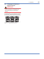
1.3 ATEX Documentation
This procedure is only applicable to the countries in European Union.
GB
DK
SK
CZ
I
LT
E
LV
NL
EST
PL
SF
SLO
P
H
F
BG
D
RO
S
M
GR
IM 01C22J01-01E
2.
2-1
<2. Handling Cautions>
Handling Cautions
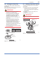
2.2 Unpacking
This chapter describes important cautions
regarding how to handle the transmitter. Read
carefully before using the transmitter.
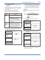
The EJA Series pressure transmitters are
thoroughly tested at the factory before shipment.
When the transmitter is delivered, visually check
them to make sure that no damage occurred during
shipment.
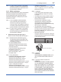
Also check that all transmitter mounting hardware
shown in Figure 2.1 is included. If the transmitter
was ordered without the mounting bracket, the
transmitter mounting hardware is not included. After
checking the transmitter, repack it in the way it was
delivered until installation.
Transmitter
mounting bolt
U-bolt
Mounting bracket
U-bolt nut
Figure 2.1
F0201.ai
Transmitter Mounting Hardware
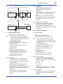
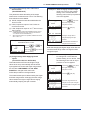
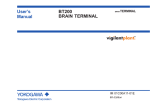
2.1 Model and Specifications
Check
The model name and specifications are indicated
on the name plate attached to the case. If the
reverse operating mode was ordered (reverse
signal), ‘REVERSE’ will be inscribed in field*1.
When moving the transmitter to the installation site,
keep it in its original packaging. Then, unpack the
transmitter there to avoid damage on the way.
2.3 Storage
The following precautions must be observed when
storing the instrument, especially for a long period.
(a) Select a storage area which meets the following
conditions:
• It is not exposed to rain or water.
• It suffers minimum vibration and shock.
• It has an ambient temperature and relative
humidity within the following ranges.
Ambient temperature:
-40 to 85°C without integral indicator
-30 to 80°C with integral indicator
Relative humidity:
5% to 100% R.H. (at 40°C)
Preferred temperature and humidity:
approx. 25°C and 65% R.H.
(b) When storing the transmitter, repack it as nearly
as possible to the way it was packed when
delivered from the factory.
(c) If storing a transmitter that has been used,
thoroughly clean the diaphragm surface of the
diaphragm seal (pressure-detector section), so
that no measured fluid remains on them. Also
make sure before storing that the pressuredetector and transmitter assemblies are
securely mounted.
2.4 Selecting the Installation
Location
The transmitter is designed to withstand severe
environmental conditions. However, to ensure
stable and accurate operation for years, observe
the following precautions when selecting an
installation location.
: Refer to USER'S MANUAL
F0202.ai
Figure 2.2
Name Plate Example of TIIS Flameproof
Type
IM 01C22J01-01E
(a) Ambient Temperature
Avoid locations subject to wide temperature
variations or a significant temperature gradient.
If the location is exposed to radiant heat from
plant equipments, provide adequate thermal
insulation and/or ventilation.
(b) Ambient Atmosphere
Avoid installing the transmitter in a corrosive
atmosphere. If the transmitter must be installed
in a corrosive atmosphere, there must be
adequate ventilation as well as measures to
prevent intrusion or stagnation of rain water in
conduits.
(c) Shock and Vibration
Select an installation site suffering minimum
shock and vibration (although the transmitter is
designed to be relatively resistant to shock and
vibration).
(d) Installation of Explosion-protected Transmitters
Explosion-protected transmitters can be
installed in hazardous areas according to the
types of gases for which they are certified.
See Subsection 2.9 “Installation of Explosion
Protected Type Transmitters.”
2.5 Pressure Connection
WARNING
• Instrument installed in the process is under
pressure. Never loosen or tighten the flange
bolts to avoid the dangerous spouting of
process fluid.
• Since the accumulated process fluid may be
toxic or otherwise harmful, take appropriate
care to avoid contact with the skin, eyes
or body, or inhalation of vapors even after
dismounting the instrument from process line
for maintenance.
The following precautions must be observed
in order to safely operate the transmitter under
pressure.
(a) Never apply a pressure higher than the
specified maximum working pressure.
(b) Never loosen or tighten the bolts securing the
diaphragm seal flanges when the assembly
is under pressure. Do it after releasing the
process pressure if required.
2-2
<2. Handling Cautions>
2.6 Waterproofing of Cable
Conduit Connections
Apply a non-hardening sealant to the threads
to waterproof the transmitter cable conduit
connections.
(See Figure 5.7, 5.8 and 5.10.)
2.7 Restrictions on Use of Radio
Transceiver
IMPORTANT
Although the transmitter has been designed to
resist high frequency electrical noise, if a radio
transceiver is used near the transmitter or its
external wiring, the transmitter may be affected
by high frequency noise pickup. To test for such
effects, bring the transceiver in use slowly from a
distance of several meters from the transmitter,
and observe the measurement loop for noise
effects. Thereafter, always use the transceiver
outside the area affected by noise.
2.8 Insulation Resistance and
Dielectric Strength Test
Since the transmitter has undergone insulation
resistance and dielectric strength tests at the factory
before shipment, normally these tests are not
required.
However, if required, observe the following
precautions in the test procedures.
(a) Do not perform such tests more frequently than
is absolutely necessary. Even test voltages that
do not cause visible damage to the insulation
may degrade the insulation and reduce safety
margins.
(b) Never apply a voltage exceeding 500 V DC
(100 V DC with an internal lightning protector)
for the insulation resistance test, nor a voltage
exceeding 500 V AC (100 V AC with an internal
lightning protector) for the dielectric strength
test.
(c) Before conducting these tests, disconnect
all signal lines from the transmitter terminals.
Perform the tests in the following procedure:
IM 01C22J01-01E
• Insulation Resistance Test
1)Short-circuit the + and – SUPPLY terminals in
the terminal box.
2)Turn OFF the insulation tester. Then connect
the insulation tester plus (+) lead wire to the
shorted SUPPLY terminals and the minus (–)
leadwire to the grounding terminal.
3)Turn ON the insulation tester power and
measure the insulation resistance. The voltage
should be applied short as possible to verify
that the insulation resistance is at least 20 MΩ.
4)After completing the test and being very careful
not to touch exposed conductors disconnect
the insulation tester and connect a 100 kΩ
resistor between the grounding terminal and
the shortcircuiting SUPPLY terminals. Leave
this resistor connected at least one second to
discharge any static potential. Do not touch the
terminals while it is discharging.
• Dielectric Strength Test
1)Short-circuit the + and – SUPPLY terminals in
the terminal box.
2)Turn OFF the dielectric strength tester. Then
connect the tester between the shorted
SUPPLY terminals and the grounding terminal.
Be sure to connect the grounding lead of the
dielectric strength tester to the ground terminal.
3)Set the current limit on the dielectric strength
tester to 10 mA, then turn ON the power and
gradually increase the test voltage from ‘0’ to
the specified voltage.
4)When the specified voltage is reached, hold it
for one minute.
5)After completing this test, slowly decrease the
voltage to avoid any voltage surges.
2.9 Installation of Explosion
Protected Type
In this section, further requirements and differences
and for explosionproof type instrument are
described.
For explosionproof type instrument, the description
in this chapter is prior to other description in this
users manual.
For the intrinsically safe equipment and
explosionproof equipment, in case the instrument
is not restored to its original condition after any
repair or modification undertaken by the customer,
intrinsically safe construction or explosionproof
2-3
<2. Handling Cautions>
construction is damaged and may cause dangerous
condition. Please contact Yokogawa for any repair
or modification required to the instrument.
NOTE
For FOUNDATION Fieldbus and PROFIBUS
PA explosion protected type, please refer to
IM 01C22T02-01E and IM 01C22T03-00E
respectively.
CAUTION
This instrument is tested and certified as
intrinsically safe type or explosionproof
type. Please note that the construction of
the instrument, installation, external wiring,
maintenance or repair is strictly restricted, and
non-observance or negligence of this restriction
would result in dangerous condition.
WARNING
To preserve the safety of explosionproof
equipment requires great care during mounting,
wiring, and piping. Safety requirements also
place restrictions on maintenance and repair
activities. Please read the following sections very
carefully.
2.9.1 FM Approval
a. FM Intrinsically Safe Type
Caution for FM intrinsically safe type. (Following
contents refer “DOC. No. IFM012-A12 P.1 and
2.”)
Note 1. Model EJA Series pressure transmitters
with optional code /FS1 are applicable for
use in hazardous locations.
• Applicable Standard: FM3600, FM3610,
FM3611, FM3810, ANSI/NEMA250
• Intrinsically Safe for Class I, Division 1,
Groups A, B, C & D. Class II, Division 1,
Groups E, F & G and Class III, Division 1
Hazardous Locations.
• Nonincendive for Class I, Division 2, Groups
A, B, C & D. Class II, Division 2, Groups E,
F & G and Class III, Division 1 Hazardous
Locations.
IM 01C22J01-01E
• Outdoor hazardous locations, NEMA 4X.
• Temperature Class: T4
• Ambient temperature: –40 to 60°C
Note 2. Entity Parameters
• Intrinsically Safe Apparatus Parameters
[Groups A, B, C, D, E, F and G]
Vmax = 30 V
Ci = 22.5 nF
Imax = 165 mA
Li = 730 µH
Pmax = 0.9 W
* Associated Apparatus Parameters
(FM approved barriers)
Voc ≤ 30 V
Ca > 22.5 nF
Isc ≤ 165 mA
La > 730 µH
Pmax ≤ 0.9 W
• Intrinsically Safe Apparatus Parameters
[Groups C, D, E, F and G]
Vmax = 30 V
Ci = 22.5 nF
Imax = 225 mA
Li = 730 µH
Pmax = 0.9 W
* Associated Apparatus Parameters
(FM approved barriers)
Voc ≤ 30 V
Ca > 22.5 nF
Isc ≤ 225 mA
La > 730 µH
Pmax ≤ 0.9 W
•
Entity Installation Requirements
Vmax ≥ Voc or Vt, Imax ≥ Isc or It,
Pmax (IS Apparatus) ≥ Pmax (Barrier)
Ca ≥ Ci + Ccable, La ≥ Li + Lcable
Note 3. Installation
• Barrier must be installed in an enclosure that
meets the requirements of ANSI/ISA S82.01.
• Control equipment connected to barrier must
not use or generate more than 250 V rms or
V dc.
• Installation should be in accordance with
ANSI/ISA RP12.6 “Installation of Intrinsically
Safe Systems for Hazardous (Classified)
Locations” and the National Electric Code
(ANSI/NFPA 70).
• The configuration of associated apparatus
must be FMRC Approved.
• Dust-tight conduit seal must be used when
installed in a Class II, III, Group E, F and G
environments.
• Associated apparatus manufacturer’s
installation drawing must be followed when
installing this apparatus.
• The maximum power delivered from the
barrier must not exceed 0.9 W.
2-4
<2. Handling Cautions>
• Note a warning label worded
“SUBSTITUTION OF COMPONENTS
MAY IMPAIR INTRINSIC SAFETY,” and
“INSTALL IN ACCORDANCE WITH DOC.
No. IFM012-A12 P.1 and 2.”
Note 4. Maintenance and Repair
• The instrument modification or parts
replacement by other than authorized
representative of Yokogawa Electric
Corporation is prohibited and will void
Factory Mutual Intrinsically safe and
Nonincendive Approval.
[Intrinsically Safe]
Hazardous Location
Nonhazardous Location
Class I, II, III, Division 1,
Groups A, B, C, D, E, F, G
EJA Series Pressure
Transmitters
+
Supply
–
Safety Barrier
+
+
–
–
General
Purpose
Equipment
+
–
[Nonincendive]
Hazardous Location
Nonhazardous Location
Class I, II, Division 2,
Groups A, B, C, D, E, F, G
Class III, Division 1.
General
Purpose
Equipment
EJA Series Pressure
Transmitters
+
Supply
–
+
Not Use
Safety Barrier
–
F0203.ai
b. FM Explosionproof Type
Caution for FM explosionproof type.
Note 1. Model EJA Series differential, gauge,
and absolute pressure transmitters with
optional code /FF1 are applicable for use in
hazardous locations.
• Applicable Standard: FM3600, FM3615,
FM3810, ANSI/NEMA250
• Explosionproof for Class I, Division 1,
Groups B, C and D.
• Dust-ignitionproof for Class II/III, Division 1,
Groups E, F and G.
• Outdoor hazardous locations, NEMA 4X.
• Temperature Class: T6
• Ambient Temperature: –40 to 60°C
• Supply Voltage: 42 V dc max.
• Output signal: 4 to 20 mA
IM 01C22J01-01E
Note 2. Wiring
• All wiring shall comply with National Electrical
Code ANSI/NEPA70 and Local Electrical
Codes.
• When installed in Division 1, “FACTORY
SEALED, CONDUIT SEAL NOT
REQUIRED.”
Note 3. Operation
• Keep the “CAUTION” nameplate attached to
the transmitter.
CAUTION: OPEN CIRCUIT BEFORE
REMOVING COVER. SEAL ALL CONDUITS
WITHIN 18 INCHES. WHEN INSTALLED
IN DIV.1, “FACTORY SEALED, CONDUIT
SEAL NOT REQUIRED.” INSTALL IN
ACCORDANCE WITH THE INSTRUCTION
MANUAL IM 1C22.
• Take care not to generate mechanical
sparking when accessing to the instrument
and peripheral devices in a hazardous
location.
Note 4. Maintenance and Repair
• The instrument modification or parts
replacement by other than authorized
representative of Yokogawa Electric
Corporation is prohibited and will void
Factory Mutual Explosionproof Approval.
c. FM Intrinsically Safe Type/FM
Explosionproof Type
Model EJA Series pressure transmitters with
optional code /FU1 can be selected the type
of protection (FM Intrinsically Safe or FM
Explosionproof) for use in hazardous locations.
Note 1. For the installation of this transmitter,
once a particular type of protection is
selected, any other type of protection
cannot be used. The installation must be in
accordance with the description about the
type of protection in this instruction manual.
Note 2. In order to avoid confusion, unnecessary
marking is crossed out on the label other
than the selected type of protection when
the transmitter is installed.
2-5
<2. Handling Cautions>
2.9.2 CSA Certification
a. CSA Intrinsically Safe Type
Caution for CSA Intrinsically safe type.
(Following contents refer to “DOC No.
ICS003-A12 P.1-1 and P.1-2.”)
Note 1. Model EJA Series differential, gauge,
and absolute pressure transmitters with
optional code /CS1 are applicable for use
in hazardous locations
Certificate: 1053843
• Applicable Standard: C22.2 No.0, No.0.4,
No.25, No.30, No.94, No.142, No.157,
No.213
• Intrinsically Safe for Class I, Division 1,
Groups A, B, C & D. Class II, Division 1,
Groups E, F & G and Class III, Division 1
Hazardous Locations.
• Nonincendive for Class I, Division 2, Groups
A, B, C & D, Class II, Division 2, Groups F &
G, and Class III, Hazardous Locations. (not
use Safety Barrier)
• Encl. “Type 4X”
• Temperature Class: T4
• Ambient temperature: –40* to 60°C
* –15°C when /HE is specified.
• Process Temperature: 120°C max.
Note 2. Entity Parameters
• Intrinsically safe ratings are as follows:
Maximum Input Voltage (Vmax) = 30 V
Maximum Input Current (Imax) = 165 mA
Maximum Input Power (Pmax) = 0.9 W
Maximum Internal Capacitance (Ci) = 22.5nF
Maximum Internal Inductance (Li) = 730 μH
* Associated apparatus (CSA certified barriers)
Maximum output voltage (Voc) ≤ 30 V
Maximum output current (Isc) ≤ 165 mA
Maximum output power (Pmax) ≤ 0.9 W
Note 3. Installation
• All wiring shall comply with Canadian
Electrical Code Part I and Local Electrical
Codes.
• The instrument modification or parts
replacement by other than authorized
representative of Yokogawa Electric
Corporation and Yokogawa Corporation
of America is prohibited and will void
Canadian Standards Intrinsically safe and
nonincendive Certification.
IM 01C22J01-01E
[Intrinsically Safe]
Hazardous Location
Nonhazardous Location
Class I, II, III, Division 1,
Groups A, B, C, D, E, F, G
EJA Series Pressure
Transmitters
+
Supply
–
Safety Barrier
+
+
–
–
General
Purpose
Equipment
+
–
[Nonincendive]
Hazardous Location
Nonhazardous Location
Class I, II, Division 2,
Groups A, B, C, D, E, F, G
Class III.
General
Purpose
Equipment
EJA Series Pressure
Transmitters
+
Supply
2-6
<2. Handling Cautions>
–
+
Not Use
Safety Barrier
–
F0204.ai
b. CSA Explosionproof Type
Caution for CSA explosionproof type.
Note 1. Model EJA Series differential, gauge,
and absolute pressure transmitters with
optional code /CF1 are applicable for use
in hazardous locations:
Certificate: 1089598
• Applicable Standard: C22.2 No.0, No.0.4,
No.25, No.30, No.94, No.142
• Explosionproof for Class I, Division 1,
Groups B, C and D.
• Dust-ignitionproof for Class II/III, Division 1,
Groups E, F and G.
• Encl “Type 4X”
• Temperature Class: T6, T5, and T4
• Process Temperature:
85°C (T6), 100°C (T5), and 120°C (T4)
• Ambient Temperature: –40* to 80°C
• When installed in Division 2, “SEALS NOT
REQUIRED.”
Note 3. Operation
• Keep the “CAUTION” label attached to the
transmitter.
CAUTION: OPEN CIRCUIT BEFORE
REMOVING COVER.
OUVRIR LE CIRCUIT AVANT D´NLEVER
LE COUVERCLE.
• Take care not to generate mechanical
sparking when accessing to the instrument
and peripheral devices in a hazardous
location.
Note 4. Maintenance and Repair
• The instrument modification or parts
replacement by other than authorized
representative of Yokogawa Electric
Corporation and Yokogawa Corporation of
America is prohibited and will void Canadian
Standards Explosionproof Certification.
Non-Hazardous Hazardous Locations Division 1
Locations
Non-hazardous
Location
Equipment
42 V DC Max.
4 to 20 mA DC
Signal
50 cm Max.
Sealing Fitting
Conduit
EJA Series
Non-Hazardous Hazardous Locations Division 2
Locations
Non-hazardous
Location
Equipment
42 V DC Max.
4 to 20 mA DC
Signal
Sealing Fitting
F0205.ai
* –15°C when /HE is specified.
• Supply Voltage: 42 V dc max.
• Output Signal: 4 to 20 mA
Note 2. Wiring
• All wiring shall comply with Canadian
Electrical Code Part I and Local Electrical
Codes.
• In hazardous location, wiring shall be in
conduit as shown in the figure.
CAUTION: SEAL ALL CONDUITS WITHIN
50 cm OF THE ENCLOSURE.
UN SCELLEMENT DOIT ÊTRE INSTALLÉ À
MOINS DE 50 cm DU BÎTIER.
EJA Series
c. CSA Intrinsically Safe Type/CSA
Explosionproof Type
Model EJA Series pressure transmitters with
optional code /CU1 can be selected the type
of protection (CSA Intrinsically Safe or CSA
Explosionproof) for use in hazardous locations.
Note 1. For the installation of this transmitter,
once a particular type of protection is
selected, any other type of protection
cannot be used. The installation must be in
accordance with the description about the
type of protection in this instruction manual.
IM 01C22J01-01E
Note 2. In order to avoid confusion, unnecessary
marking is crossed out on the label other
than the selected type of protection when
the transmitter is installed.
2.9.3 IECEx Certification
Model EJA Series differential, gauge, and absolute
pressure transmitters with optional code /SU2
can be selected the type of protection (IECEx
Intrinsically Safe/type n or flameproof) for use in
hazardous locations.
Note 1. For the installation of this transmitter,
once a particular type of protection is
selected, any other type of protection
cannot be used. The installation must be in
accordance with the description about the
type of protection in this instruction manual.
Note 2. In order to avoid confusion, unnecessary
marking is crossed out on the label other
than the selected type of protection when
the transmitter is installed.
a. IECEx Intrinsically Safe Type / type n
Caution for IECEx Intrinsically safe and type n.
Note 1. Model EJA Series differential, gauge,
and absolute pressure transmitters with
optional code /SU2 are applicable for use
in hazardous locations.
• No. IECEx KEM 06.0007X
• Applicable Standard: IEC 60079-0:2004,
IEC 60079-11:1999, IEC 60079-15:2005,
IEC 60079-26:2004
• Type of Protection and Marking Code:
Ex ia IIC T4, Ex nL IIC T4
• Ambient Temperature: –40 to 60°C
• Max. Process Temp.: 120°C
• Enclosure: IP67
Note 2. Entity Parameters
• Intrinsically safe ratings are as follows:
Maximum Input Voltage (Ui) = 30 V
Maximum Input Current (Ii) = 165 mA
Maximum Input Power (Pi) = 0.9 W
Maximum Internal Capacitance (Ci) = 22.5nF
Maximum Internal Inductance (Li) = 730 μH
• Type “n” ratings are as follows:
Maximum Input Voltage (Ui) = 30 V
Maximum Internal Capacitance (Ci) = 22.5nF
Maximum Internal Inductance (Li) = 730 μH
2-7
<2. Handling Cautions>
• Installation Requirements
Uo ≤ Ui, Io ≤ Ii, Po ≤ Pi, Co ≥ Ci + Ccable,
Lo ≥ Li + Lcable, Uo, Io, Po, Co, and Lo are
parameters of barrier.
Note 3. Installation
• In any safety barreir used output current
must be limited by a resistor ‘R’ such that
Io = Uo/R.
• The safety barrier must be IECEx certified.
• Input voltage of the safety barrier must be
less than 250 Vrms/Vdc.
• The instrument modification or parts
replacement by other than authorized
representative of Yokogawa Electric
Corporation and will void IECEx Intrinsically
safe and type n certification.
• The cable entry devices and blanking
elements for type n shall be of a certified type
providing a level of ingress protection of at
least IP54, suitable for the conditions of use
and correctly installed.
• Electrical Connection:
The type of electrical connection is stamped
near the electrical connection port according
to the following marking.
Screw Size
Marking
ISO M20 × 1.5 female
M
ANSI 1/2 NPT female
A
Location of the marking
F0206.ai
Note 4. Operation
• WARNING:
WHEN AMBIENT TEMPERATURE ≥ 55°C,
USE THE HEAT-RESISTING CABLES ≥
90°C.
Note 5. Special Conditions for Safe Use
• WARNING:
IN THE CASE WHERE THE ENCLOSURE
OF THE PRESSURE TRANSMITTER IS
MADE OF ALUMINUM, IF IT IS MOUNTED
IN AN AREA WHERE THE USE OF ZONE
0 IS REQUIRED, IT MUST BE INSTALLED
SUCH, THAT, EVEN IN THE EVENT OF
RARE INCIDENTS, IGNITION SOURCES
DUE TO IMPACT AND FRICTION SPARKS
ARE EXCLUDED.
IM 01C22J01-01E
[Intrinsically Safe]
Hazardous Location
Nonhazardous Location
Group I/IIC, Zone 0
EJA Series Pressure
Transmitters
+
Supply
IECEx certified
Safety Barrier
+
+
–
–
–
General
Purpose
Equipment
+
–
[type n]
Hazardous Location
Nonhazardous Location
Group IIC, Zone 2
EJA Series Pressure
Transmitters
+
Supply
2-8
<2. Handling Cautions>
–
IECEx Certified
Equipment [nL]
+
Not Use
Safety Barrier
–
F0207.ai
b. IECEx Flameproof Type
Caution for IECEx flameproof type.
Note 1. Model EJA Series differential, gauge,
and absolute pressure transmitters with
optional code /SU2 are applicable for use
in hazardous locations:
• No. IECEx KEM 06.0005
• Applicable Standard: IEC 60079-0:2004,
IEC 60079-1:2003
• Type of Protection and Marking Code:
Ex d IIC T6...T4
• Enclosure: IP67
• Maximum Process Temperature:
120°C (T4), 100°C (T5), 85°C (T6)
• Ambient Temperature: –40 to 75°C (T4),
–40 to 80°C (T5), –40 to 75°C (T6)
• Supply Voltage: 42 V dc max.
• Output Signal: 4 to 20 mA dc
Note 2. Wiring
• In hazardous locations, the cable entry
devices shall be of a certified flameproof
type, suitable for the conditions of use and
correctly installed.
• Unused apertures shall be closed with
suitable flameproof certified blanking
elements. (The plug attached is certificated
as the flame proof IP67 as a part of this
apparatus.)
• In case of ANSI 1/2 NPT plug, ANSI
hexagonal wrench should be applied to
screw in.
Note 3. Operation
• WARNING:
AFTER DE-ENERGIZING, DELAY 10
MINUTES BEFORE OPENING.
• WARNING:
WHEN AMBIENT TEMPERATURE ≥ 70°C,
USE THE HEAT-RESISTING CABLES ≥
90°C.
• Take care not to generate mechanical
sparking when accessing to the instrument
and peripheral devices in a hazardous
location.
Note 4. Maintenance and Repair
• The instrument modification or parts
replacement by other than authorized
representative of Yokogawa Electric
Corporation is prohibited and will void IECEx
Certification.
2.9.4 ATEX Certification
(1) Technical Data
a. ATEX Intrinsically Safe Type
Caution for ATEX Intrinsically safe type.
Note 1. Model EJA Series differential, gauge,
and absolute pressure transmitters with
optional code /KS2 for potentially explosive
atmospheres:
• No. KEMA 02ATEX1030 X
• Applicable Standard: EN 50014:1997,
EN 50020:1994, EN 50284:1999
• Type of Protection and Marking code:
EEx ia IIC T4
• Temperature Class: T4
• Enclosure: IP67
• Process Temperature: 120°C max.
• Ambient Temperature: –40 to 60°C
Note 2. Electrical Data
• In type of explosion protection intrinsic
safety EEx ia IIC only for connection to a
certified intrinsically safe circuit with following
maximum values:
Ui = 30 V
Ii = 165 mA
Pi = 0.9 W
Effective internal capacitance; Ci = 22.5 nF
Effective internal inductance; Li = 730 μH
Note 3. Installation
• All wiring shall comply with local installation
requirements. (Refer to the installation
diagram)
IM 01C22J01-01E
2-9
<2. Handling Cautions>
Note 4. Maintenance and Repair
• The instrument modification or parts
replacement by other than authorized
representative of Yokogawa Electric
Corporation is prohibited and will void KEMA
Intrinsically safe Certification.
Note 3. Installation
• All wiring shall comply with local installation
requirement.
• The cable entry devices shall be of a certified
flameproof type, suitable for the conditions of
use.
Note 5. Special Conditions for Safe Use
• In the case where the enclosure of the
Pressure Transmitter is made of aluminium,
if it is mounted in an area where the use of
category 1 G apparatus is required, it must
be installed such, that, even in the event of
rare incidents, ignition sources due to impact
and friction sparks are excluded.
Note 4. Operation
• Keep the “CAUTION” label to the transmitter.
CAUTION: AFTER DE-ENERGIZING,
DELAY 10 MINUTES BEFORE OPENING.
WHEN THE AMBIENT TEMP. ≥ 70°C, USE
HEAT-RESISTING CABLES ≥ 90°C.
• Take care not to generate mechanical
sparking when accessing to the instrument
and peripheral devices in a hazardous
location.
[Installation Diagram]
Hazardous Location
Nonhazardous Location
Transmitter
Supply
+
+
–
–
Safety Barrier *1
Note 5. Maintenance and Repair
• The instrument modification or parts
replacement by other than authorized
representative of Yokogawa Electric
Corporation is prohibited and will void KEMA
Flameproof Certification.
(2) Electrical Connection
F0208.ai
*1:In any safety barriers used the output current must be
limited by a resistor “R” such that Imaxout-Uz/R.
b. ATEX Flameproof Type
Caution for ATEX flameproof type.
Note 1. Model EJA Series differential, gauge,
and absolute pressure transmitters
with optional code /KF21 for potentially
explosive atmospheres:
• No. KEMA 02ATEX2148
• Applicable Standard: EN 60079-0:2006,
EN 60079-1:2004
• Type of Protection and Marking Code:
Ex d IIC T6...T4
• Temperature Class: T6, T5, and T4
• Enclosure: IP67
• Maximum Process Temperature:
85°C (T6), 100°C (T5), and 120°C (T4)
• Ambient Temperature:
T4 and T6; –40* to 75°C, T5; –40* to 80°C
* –15°C when /HE is specified.
Note 2. Electrical Data
• Supply voltage: 42 V dc max.
• Output signal: 4 to 20 mA
The type of electrical connection is stamped
near the electrical connection port according to
the following marking.
Screw Size
Marking
ISO M20 × 1.5 female
M
ANSI 1/2 NPT female
A
Location of the marking
F0206.ai
(3) Installation
WARNING
• All wiring shall comply with local installation
requirement and local electrical code.
• There is no need of the conduit seal for
both of Division 1 and Division 2 hazardous
locations because this product is sealed at
factory.
• In case of ANSI 1/2 NPT plug, ANSI
hexagonal wrench should be applied to
screw in.
IM 01C22J01-01E
2-10
<2. Handling Cautions>
(4) Operation
WARNING
• OPEN CIRCUIT BEFORE REMOVING
COVER. INSTALL IN ACCORDANCE WITH
THIS USER’S MANUAL
• Take care not to generate mechanical
sparking when access to the instrument and
peripheral devices in hazardous locations.
*1: The third figure from the last shows the last one figure
of the year of production. For example, the production
year of the product engraved in “NO.” column on the
name plate as follows is 2001.
12A819857
132
The year 2001
*2:“180-8750” is a zip code which represents the
following address.
2-9-32 Nakacho, Musashino-shi, Tokyo Japan
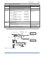
2.9.5 TIIS Certification
(5) Maintenance and Repair
a. TIIS Flameproof Type
WARNING
The instrument modification or parts replacement
by other than authorized Representative of
Yokogawa Electric Corporation is prohibited and
will void the certification.
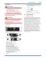
(6) Name Plate
Name plate
The model EJA Series pressure transmitter with
optional code /JF3, which has obtained certification
according to technical criteria for explosionprotected construction of electric machinery and
equipment (Standards Notification No. 556 from
the Japanese Ministry of Labor) conforming to IEC
standards, is designed for hazardous areas where
inflammable gases or vapors may be present. (This
allows installation in Division 1 and 2 areas)
To preserve the safety of flameproof equipment
requires great care during mounting, wiring, and
piping. Safety requirements also place restrictions
on maintenance and repair activities. Users
absolutely must read “Installation and Operating
Precautions for TIIS Flameproof Equipment” at the
end of this manual.
: Refer to USER'S MANUAL
Tag plate for flameproof type
Tag plate for intrinsically safe type
F0210.ai
MODEL: Specified model code.
STYLE: Style code.
SUFFIX: Specified suffix code.
SUPPLY: Supply voltage.
OUTPUT: Output signal.
MWP: Maximum working pressure.
CAL RNG: Specified calibration range.
DISP MODE: Specified display mode.
OUTPUT MODE: Specified output mode.
NO.: Serial number and year of production*1.
TOKYO 180-8750 JAPAN:
The manufacturer name and the
address*2.
IM 01C22J01-01E
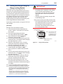
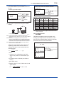
CAUTION
CAUTION
(For TIIS flameproof type without integral
indicator)
When the fill fluid near the sensor part moves
from within, the instrument outputs a failure
signal either high or low of the specific signal.
In that case, generate the alarm to identify that
the failure signal is output since the event may
invalidate the flameproof approval.
If the optional integral indicator is equipped, the
indicator identifies the alarm on its display.
Therefore, no other alarm generation is
necessary.
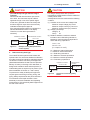
Hazardous Location
Nonhazardous Location
4 to 20 mA DC
Transmitter
1 to 5 V DC
Power
Supply
DCS
Display
F0211.ai
Figure 2.3
2-11
<2. Handling Cautions>
Example of using DCS (Distributed
Control System)
b. TIIS Intrinsically Safe Type
The model EJA Series pressure transmitter with
optional code /JS3, which has obtained certification
according to technical criteria for explosionprotected
construction of electric machinery and equipment
(Standards Notification No.556 from the Japanese
Ministry of Labor) conforming to IEC standards, is
designed for hazardous areas where explosive or
inflammable gases or vapors may be present. (This
allows installation in Division 0, 1 and 2 areas)
To preserve the safety of flameproof equipment
requires great care during mounting, wiring, and
piping. Safety requirements also place restrictions
on maintenance and repair activities. Users
absolutely must read “Installation and Operating
Precautions for TIIS Intrinsically Safe Equipment” at
the end of this manual.
For using a safety-barrier with a pressure
transmitter, the safety-barrier must be certified as
a safety-barrier itself.
A safety-barrier must be used under the following
condition.
(1) Condition of the current and voltage limits
Maximum output voltage (Uo) ≤ 28 V
Maximum output current (Io) ≤ 94.3 mA
Maximum output power (Po) ≤ 0.66 W
(2) Category and Group
Category ia
Group
IIC
(3) Relations between a maximum allowed
inductance and a field wiring inductance,
between a maximum allowed capacitance
and a field wiring capacitance.
Lo ≥ Li + Lw
Co ≥ Ci + Cw
(Li = 730μH, Ci=11nF)
Lo = Maximum external inductance
Li = Maximum internal inductance
Lw = Field wiring inductance
Go = Maximum external capacitance
Ci = Maximum internal capacitance
Cw = Field wiring capacitance
Hazardous Location
4 to 20 mA DC
Transmitter
Safety Barrier
Li=730 µH
Ci=11 nF
Figure 2.5
Nonhazardous
Location
Lw, Cw
Lo, Co
F0212.ai
Diagram for Connecting Safety
Barrier
IM 01C22J01-01E
<2. Handling Cautions>
2.10 EMC Conformity Standards
2.12 Low Voltage Directive
EN 61326-1 Class A, Table 2 (For use in industrial
locations)
Applicable standard: EN 61010-1
EN 61326-2-3
EN 61326-2-5 (for Fieldbus)
CAUTION
This instrument is a Class A product, and it is
designed for use in the industrial environment.
Please use this instrument in the industrial
environment only.
NOTE
YOKOGAWA recommends customer to apply
the Metal Conduit Wiring or to use the twisted
pair Shield Cable for signal wiring to conform the
requirement of EMC Regulation, when customer
installs the EJA Series Transmitters to the plant.
2.11 PED (Pressure Equipment
Directive)
2-12
(1) Pollution Degree 2
“Pollution degree” describes the degree to
which a solid, liquid, or gas which deteriorates
dielectric strength or surface resistivity
is adhering. “2” applies to normal indoor
atmosphere. Normally, only non-conductive
pollution occurs. Occasionally, however,
temporary conductivity caused by condensation
must be expected.
(2) Installation Category I
“Overvoltage category (Installation category)”
describes a number which defines a transient
overvoltage condition. It implies the regulattion
for impulse withstand voltage. “I” applies to
electrical equipment which is supplied from the
circuit when appropriate transient overvoltage
control means (interfaces) are provided.
(3) Altitude of installation site:
Max. 2,000 m above sea level
(4) Indoor/Outdoor use
EJA series of pressure transmitters are categorized
as pressure accessories of this directive 97/23/
EC, which corresponds to Article 3, Paragraph 3
of PED, denoted as Sound Engineering Practice
(SEP).
IM 01C22J01-01E
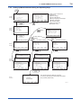
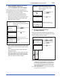
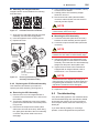
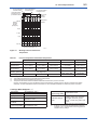
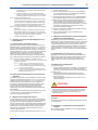
3.
3-1
<3. Component Names>
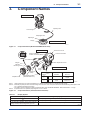
Component Names
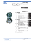
Transmitter section*
*See below for details.
Capillary tube
Cover flange
Diaphragm seal
Diaphragm
Flange
Pressure-detector section
F0301.ai
Figure 3.1
Component Names (Model EJA438W External View)
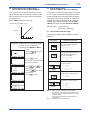
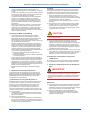
Terminal box cover
Transmitter section
External indicator
conduit connection (Note 1)
Conduit connection
CPU assembly
Zero-adjustment screw
Integral
indicator (Note 1)
Mounting screw
Pressure-detector section
Cover
flange
Setting pin
(CN4)
Amplifier cover
Range-setting switch (Note 1)
(See Subsection 6.5)
Setting pin (CN4)
position (Note 2)
Burn-out
direction
Output at
burn-out
H
L
HIGH
110% or
higher
H
L
LOW
-5% or
lower (Note3)
F0302.ai
Note 1: Options depend on your order specifications. For details, see Subsection 9.2, “Model and Suffix Codes.”
Note 2: • Insert the pin (CN4) as shown in the above figure into the H or L side. The pin is set to the H side for delivery (unless option code
/C1 is otherwise specified in the order).
• The setting can be confirmed by calling up parameter D52 using the BRAIN TERMINAL. Refer to Subsection. 7.3.2 (8).
Note 3: If optional code /F1 is specified, output signal is –2.5% or lower.
Figure 3.2
Component Names (Transmitter Section Details)
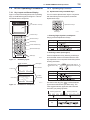
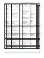
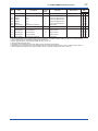
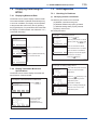
Table 3.1
Display Symbol
Display Symbol
Meaning of Display Symbol
The output signal being zero-adjusted is increasing.
The output signal being zero-adjusted is decreasing.
%, Pa, kPa, MPa, kgf/cm2, gf/cm2, mbar, bar, atm,
mmHg, mmH2O, inH2O, inHg, ftH2O, psi, Torr
Select one of these sixteen available engineering units for the display.
T0301.ai
IM 01C22J01-01E
4.
4-1
<4. Installation>
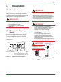
Installation
4.1 Precautions
Before installing the transmitter, read the cautionary
notes in Section 2.4, “Selecting the Installation
Location.” For additional information on the ambient
conditions allowed at the installation location, refer
to Subsection 9.1 “Standard Specifications.”
IMPORTANT
• When welding piping during construction,
take care not to allow welding currents to
flow through the transmitter.
• Do not step on this instrument after
installation.
Mount the diaphragm seals using the flanges
as shown in Figure 4.1. Figure 4.2 shows how
to mount the diaphragm seals on a tank. The
customer should prepare the mating flange, gasket,
bolts and nuts.
Flange
Bolt
Please use a gasket which has a bigger inside
diameter than that of gasket facing (Ød) on
diaphragm seal. In case a gasket which has a
smaller inside diameter than that of gasket facing
is used, it may cause an error as the gasket
prevents diaphragm from working correctly.
(Refer to Subsection 9.4 ‘Dimensions’)
IMPORTANT
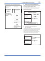
4.2 Mounting the Diaphragm
Seals
Diaphragm
IMPORTANT
Nut
• During the diaphragm seal installation,
ensure as far as possible that no seal liquid
head is applied to the diaphragm seal.
• Exercise care so as not to damage
diaphragm surface. Since the diaphragm
protrudes approx.
1mm from the flange surface, placing
the diaphragm seals with its diaphragm
surface facing downward may damage the
diaphragm surface.
• Do not sharply bend or twist capillary tube or
apply excessive stress to it.
IMPORTANT
Diaphragm seal
Install the sealed
diaphragm so that the
shank positions downward.
Ød
Gasket
The product is shipped with
these parts assembled.
Correctly install the diaphragm seals on
the high and low pressure sides of the
process, checking the label on each seal.
Capillary tube
F0401.ai
Figure 4.1
Mounting the Diaphragm Seals
F0402.ai
Figure 4.2
Installing the Diaphragm Seals to a
Tank
IM 01C22J01-01E
4-2
<4. Installation>
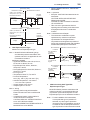
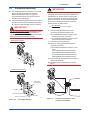
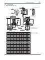
4.3 Transmitter Mounting
The transmitter can be mounted on a nominal
50 mm (2-inch) pipe using the mounting
bracket supplied, as shown in Figure 4.3
The transmitter can be mounted on either a
horizontal or a vertical pipe.
When mounting the bracket on the transmitter,
tighten the (four) bolts that hold the transmitter
to a torque of approximately 39 N·m {4 kgf·m}.
IMPORTANT
The transmitter should be installed at least 700
mm (when the model code of the material of the
wetted part is H, at least 1300 mm) below the
process connection to ensure a positive head
pressure of fill fluid. If it can not be installed at
least 700 mm below the process connection,
please use the equation below:
h=
IMPORTANT
Never loosen the four screws securing the cover
flange or the screws at the joints between the
capillary tube and cover flanges (if the seal liquid
leaks, the transmitter cannot be used).
Vertical pipe mounting
(P–P0)×dHg
×7.5×10⁻³ [mm]
ds
h: Vertical height between the process
connection and the transmitter (mm)
h≤0: Install the transmitter at least h (mm)
below the process connection
h>0: Install the transmitter at most h (mm)
above the process connection
P: Pressure in the tank (Pa abs)
P0:Minimum working pressure limit of the
transmitter (Pa abs)
If the ambient temperature range is –10 to
50°C.
5254 (Wetted parts material code S)
6980 (Wetted parts material code T)
13019 (Wetted parts material code H)
6980 (Wetted parts material code U)
ds: Specific gravity of fill fluid (at 25°C), refer to
GS 01C22J03-00E.
dHg:Specific gravity of the Mercury 13.6 (at
25°C)
Horizontal pipe mounting
h
(+)
Transmitter
mounting bolt
0
(–)
P
U-bolt nut
Mounting bracket
50mm (2-inch) pipe
Figure 4.3.
Transmitter Mounting
U-bolt
F0404.ai
F0403.ai
Figure 4.4
Example of Installation to Tank
(Caution on Installation)
IM 01C22J01-01E
4-3
<4. Installation>
4.4 Affixing the Teflon Film
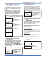
4.5 Rotating Transmitter Section
The FEP Teflon option includes a teflon film and
fluorinated oil.
Before mounting the diaphragm seal to the process
flange, affix the teflon film as follows :
The DPharp transmitter section can be rotated in
90° segments.
IMPORTANT
• Position the diaphragm seal so that the
diaphragm is in a upward position.
• Pour the fluorinated oil on the diaphragm
and gasket area covering it completely
and evenly. Be careful not to scratch the
diaphragm or change the its shape.
• Affix the teflon film over the diaphragm and
gasket area.
• Next, carefully inspect the cover and try
to identify any entrapped air between the
diaphragm and the teflon film. The air
must be removed to ensure accuracy. If air
pockets are present, use your fingers to
remove the air by starting at the center of the
diaphragm and work your way out.
• Place the gasket with the teflon film and affix
to the process flange.
(1) Remove the two Allen screws that fasten the
transmitter section and pressure-detector
section, using the Allen wrench supplied with
the transmitter.
(2) Rotate the transmitter section slowly in 90°
segments.
(3) Tighten the two Allen screws.
IMPORTANT
Do not rotate the transmitter section more than
180°.
Transmitter section
Rotate 90° or 180°
segments
Rotate 90° or 180°
segments
Conduit connection
Zero-adjustment
screw
Teflon film
PART No. Process flange size
F9347XA For 3inch (80 mm)
F9347YA For 2inch (50 mm)
Pressure-detector section
Fluorinated oil
[PART No.: F9145YN]
F0406.ai
Figure 4.6
Rotating Transmitter Section
Diaphragm
Gasket area
Diaphragm seal
F0405.ai
Figure 4.5
Affixing the Teflon Film
IM 01C22J01-01E
<4. Installation>
4-4
4.6 Changing the Direction of
Integral Indicator
IMPORTANT
Always turn OFF power, release pressure and
remove a transmitter to non-hazardous area
before disassembling and reassmbling an
indicator.
An integral indicator can be installed in the following
three directions. Follow the instructions in section
8.4 for removing and attaching the integral indicator.
F0407.ai
Figure 4.7
Integral Indicator Direction
IM 01C22J01-01E
5.
5-1
<5. Wiring>
Wiring
5.1 Wiring Precautions
IMPORTANT
• Lay wiring as far as possible from electrical
noise sources such as large capacity
transformers, motors, and power supplies.
• Remove electrical connection dust cap
before wiring.
• All threaded parts must be treated with
waterproofing sealant. (A non-hardening
silicone group sealant is recommended.)
• To prevent noise pickup, do not pass signal
and power cables through the same ducts.
• Explosion-protected instruments must
be wired in accordance with specific
requirements (and, in certain countries,
legal regulations) in order to preserve the
effectiveness of their explosionprotected
features.
• The terminal box cover is locked by an
Allen head bolt (a shrouding bolt) on
CENELEC, IECEx, and TIIS flameproof type
transmitters.
When the shrouding bolt is driven clockwise
by an Allen wrench, it is going in and cover
lock is released, and then the cover can be
opened. See Subsection 8.4 “Disassembly
and Reassembly” for details.
Refer to The “Installation and Operating
Precautions for TIIS Flameproof Equipment”
and “Installation and Operating Precautions
for TIIS Intrinsically Safe Equipment” at the
end of this manual for correct wiring.
5.2 Selecting the Wiring
Materials
(a) Use stranded leadwires or cables which are
the same as or better than 600 V grade PVC
insulated wire (JIS C3307) or equivalent.
(b) Use shielded wires in areas that are susceptible
to electrical noise.
(c) In areas with higher or lower ambient
temperatures, use appropriate wires or cables.
CAUTION
If the transmitter is flameproof and the ambient
temperature is 50°C or more, use cables having
a maximum allowable heat resistance of at
least 75°C in consideration of the instrument’s
generation of heat or the cables’ self-heating.
(d) In environment where oils, solvents, corrosive
gases or liquids may be present, use wires or
cables that are resistant to such substances.
(e) It is recommended that crimp-on solderless
terminal lugs (for 4 mm screws) with insulating
sleeves be used for leadwire ends.
5.3 Connections of External
Wiring to Terminal Box
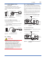
5.3.1 Power Supply Wiring Connection
Connect the power supply wiring to the SUPPLY +
and – terminals.
+
Transmitter terminal box
Power supply
–
F0501.ai
Figure 5.1
Power Supply Wiring Connection
5.3.2 External Indicator Connection
Connect wiring for external indicators to the CHECK
+ and – terminals.
(Note)Use a external indicator whose internal resistance is 10Ω
or less.
External indicator
Power supply
+
–
Transmitter terminal box
Figure 5.2
F0502.ai
External Indicator Connection
IM 01C22J01-01E
5-2
<5. Wiring>
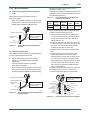
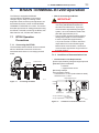
5.3.3 BRAIN TERMINAL BT200
Connection
5.4.1 Loop Configuration
Connect the BT200 to the SUPPLY + and
– terminals (Use hooks). The communication line
requires a reception resistor of 250 to 600Ω in
series.
Transmitter terminal box
Power supply
+
–
Ignore the polarity
since the BT200 is
AC-coupled to the
terminal box.
BT200
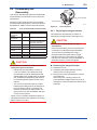
Since the DPharp uses a two-wire transmission
system, signal wiring is also used as power wiring.
DC power is required for the transmitter loop. The
transmitter and distributor are connected as shown
below.
For details of the power supply voltage and load
resistance, see Section 5.6; for communications
line requirements, see Subsection 7.1.2.
(1) General-use Type and Flameproof Type
Hazardous Location
Nonhazardous Location
F0503.ai
Figure 5.3
BT200 Connection
Transmitter terminal box
Distributor
(Power supply unit)
5.3.4 Check Meter Connection
Connect the check meter to the CHECK + and
– terminals (use hooks).
• A 4 to 20 mA DC output signal from the CHECK
+ and – terminals.
(Note)Use a check meter whose internal resistance is 10Ω or
less.
Power supply
+
Figure 5.4
Figure 5.5
F0505.ai
Connection between Transmitter and
Distributor
(2) Intrinsically Safe Type
Hazardous Location
Transmitter terminal box
Receiver
instrument
For intrinsically safe type, a safety barrier must be
included in the loop.
–
Check meter
+
–
F0504.ai
Check Meter Connection
Nonhazardous Location
Transmitter terminal box
Distributor
(Power supply unit)
5.4 Wiring
+
CAUTION
For the intrinsically safe equipment and
flameproof equipment, wiring materials and
wiring work for these equipment including
peripherals are strictly restricted. Users
absolutely must read “Installation and Operating
Precautions for TIIS Intrinsically Safe Equipment”
and “Installation and Operating Precautions for
TIIS Flameproof Equipment” at the end of this
manual prior to the work.
Receiver
instrument
–
Safety barrier
Figure 5.6
F0506.ai
Connection between Transmitter and
Distributor
IM 01C22J01-01E
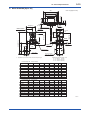
5.4.2 Wiring Installation
(1) General-use Type and Intrinsically Safe
Type
Make cable wiring using metallic conduit or
waterproof glands.
Flexible metal conduit
Apply a non-hardening
sealant to the threads
for waterproofing.
Wiring metal
conduit
Tee
Drain plug
• Measure the cable outer diameter in two
directions to within 1 mm.
• Calculate the average of the two diameters, and
use packing with an internal diameter nearest to
this value (see Table 5.1).
Table 5.1
• Apply a non-hardening sealant to the terminal
box connection port and to the threads on the
flexible metal conduit for waterproofing.
Figure 5.7
F0507.ai
Typical Wiring Using Flexible Metal
Conduit
(2) Flameproof Type (TIIS)
Wire cables through a flameproof packing adapter,
or using a flameproof metal conduit.
■ Wiring cable through flameproof packing
adapter for only TIIS flameproof type (see
Figure 5.8).
• Use only flameproof packing adapters
approved by Yokogawa.
• Apply a nonhardening sealant to the terminal
box connection port and to the threads on the
flameproof packing adapter for waterproofing.
Optional
Code
G11
G12
Flameproof Packings and Applicable
Cable Outer Diameters
Wiring Port Applicable
Identifying
Thread
Cable OD
Mark
Diameter
(mm)
16 8-10
8 to 10
G 1/2
10.1 to 12 16 10-12
Apply a non-hardening
sealant to the threads
for waterproofing.
Tee
Figure 5.8
G9601AM
Apply a non-hardnening
sealant to the threads for
waterproofing.
Flexible metal conduit
Drain plug
Part
Number
• Mounting flameproof packing adapter body to
conduit connection (see Figure 5.9)
1)Screw the flameproof packing adapter into
the terminal box until the O-ring touches the
wiring port (at least 6 full turns), and firmly
tighten the lock nut.
2)Insert the cable through the union cover, the
union coupling, the clamp nut, the clamp ring,
the gland, the washer, the rubber packing,
and the packing box, in that order.
3)Insert the end of the cable into the terminal
box.
4)Tighten the union cover to grip the cable.
When tightening the union cover, tighten
approximately one turn past the point where
the cable will no longer move up and down.
Proper tightening is important. If it is too tight,
a circuit break in the cable may occur; if not
tight enough, the flameproof effectiveness
will be compromised.
5)Fasten the cable by tightening the clamp nut.
6)Tighten the lock nut on the union cover.
7)Connect the cable wires to each terminal.
Flameproof packing adapter
Wiring metal
conduit
5-3
<5. Wiring>
F0508.ai
Typical Cable Wiring Using Flameproof
Packing Adapter
O-ring
Adapter body
Lock nut
Wrench
Packing box
Rubber packing
Washer
Gland
Clamp ring
Figure 5.9
Clamp nut
Union coupling
Lock nut
Wrench
Union cover
Cable
F0509.ai
Installing Flameproof Packing Adapter
IM 01C22J01-01E
■ Flameproof metal conduit wiring
• A seal fitting must be installed near the terminal
box connection port for a sealed construction.
• Apply a non-hardening sealant to the threads of
the terminal box connection port, flexible metal
conduit and seal fitting for waterproofing.
Non-hazardous area
Hazardous area
Apply a non-hardening
sealant to the threads
of these fittings for
waterproofing
Flameproof
heavy-gauge
steel conduit
Drain plug
Transmitter terminal box
Ground terminal
(Inside)
Gas sealing device
Flameproof flexible
metal conduit
Tee
5-4
<5. Wiring>
Seal fitting
After wiring, impregnate the fitting
with a compound to seal tubing.
F0510.ai
Figure 5.10 Typical Wiring Using Flameproof Metal
Conduit
5.5 Grounding
Grounding is always required for the proper
operation of transmitters. Follow the domestic
electrical requirements as regulated in each
country. For a transmitter with built-in lightning
protector, grounding should satisfy Class C
requirements (ground resistance of 10Ω or less).
Ground terminal
(Outside)
F0511.ai
Figure 5.11 Ground Terminals
5.6 Power Supply Voltage and
Load Resistance
When configuring the loop, make sure that the
external load resistance is within the range in the
figure below.
(Note)In case of an intrinsically safe transmitter, external load
resistance includes safety barrier resistance.
600
External
load
resistance
R (Ω)
R=
E–10.5
0.0236
Communication
applicable range
BRAIN and HART
250
Ground terminals are located on the inside and
outside of the terminal box. Either of these terminals
may be used.
0
WARNING
For TIIS flameproof type and intrinsically safe,
grounding should satisfy Class D requirements
(grounding resistance, 100Ω or less).
10.5
16.4
24.7
42
Power supply voltage E (V DC)
F0512.ai
Figure 5.12 Relationship between Power Supply
Voltage and External Load Resistance
IM 01C22J01-01E
6.
6-1
<6. Operation>
Operation
6.1 Preparation for Starting
Operation
Confirming that Transmitter is Operating
Properly
The Model EJA438W and EJA438N diaphragm
sealed gauge pressure transmitter measures
the pressure of liquids, gases, and steam. This
section describes the operation procedure for the
EJA438W as shown in Figure 6.1 when measuring
pressure in a tank.
Confirmation using the BT200
(a) Confirm that there is no leak in the connecting
part of each diaphragm seal mounting flange.
(b) Turn ON power and connect the BT200.
Open the terminal box cover and connect the
BT200 to the SUPPLY + and – terminals.
(c) Using the BT200, confirm that the transmitter is
operating properly. Check parameter values or
change the setpoints as necessary.
For BT200 operating procedures, see Chapter
7. If the transmitter is equipped with an integral
indicator, its indication can be used to confirm
that the transmitter is operating properly.
• If the wiring system is faulty, ‘communication
error’ appears on the display.
• If the transmitter is faulty, ‘SELF CHECK
ERROR’ appears on the display.
PARAM
C60:SELF CHECK
ERROR
communication error
DATA
Communication error
(Faulty wiring)
DIAG
PRNT
Self-diagnostic error
(Faulty transmitter)
F0602.ai
Confirmation using the integral indicator
• If the wiring system is faulty, the display is
blank.
• If the transmitter is faulty, an error number will
appear on the display according to the nature of
the error.
Self-diagnostic error
(Faulty transmitter)
Diaphragm seal
ESC
F0603.ai
NOTE
If any of the error indications above appears on
the display of the integral indicator or BT200,
refer to Subsection 7.5.2 for corrective action.
Capillary tube
Pressure transmitter
Verify and Change Transmitter
Parameter Setting and Values
The following parameters are the minimum settings
required for operation. The transmitter has been
shipped with these parameters. To confirm or
change the values, see Subsection 7.3.3.
Transmitter mounting pipe
50mm (2 inches)
Figure 6.1
• Measuring range … See Subsection 7.3.3 (2)
• Operation mode … See Subsection 7.3.3 (7)
F0601.ai
Liquid Flow Measurement
IM 01C22J01-01E
6.2 Zero Point Adjustment
Adjust the zero point after operating preparation is
completed.
IMPORTANT
Do not turn off the power to the transmitter
immediately after a zero adjustment. Powering
off within 30 seconds after a zero adjustment
will return the adjustment back to the previous
settings.
The zero point adjustment can be made in either
way: using the zero-adjustment screw of the
transmitter or the BT200 operation.
For output signal checking, display the parameter
A10: OUTPUT (%) in the BT200.
BT200
Output signal (%)
display
PARAM
A10:OUTPUT(%)
0.0 %
A11:ENGR OUTPUT
DIAG
PRNT
6.2.1 When you can obtain Low Range
Value from actual measured value of
0% (0 kPa, atmospheric pressure);
For pressure measurement using gauge pressure
transmitters, follow the step below before zero point
adjustment.
1) Close the tap valve (main valve).
2) Loosen the fill plug so that the pressure applied
to the transmitter is only the head of the seal
liquid.
3) Adjust the zero point at this status.
4) After the adjustment, close the fill plug and then
gradually open the tap valve.
Using the Transmitter Zero-adjustment
Screw
Before adjusting a screw, check that the parameter
J20: EXT ZERO ADJ displays ENABLE. See
Subsection 7.3.3 (11) for the setting procedure.
Use a slotted screwdriver to turn the zeroadjustment screw. Turn the screw clockwise
to increase the output or counterclockwise to
decrease the output. The zero point adjustment
can be made with a resolution of 0.01% of the
setting range. Since the degree of zero adjustments
varies with the screw turning speed, turn the screw
slowly for fine adjustment and quickly for coarse
adjustment.
A20:AMP TEMP
DATA
6-2
<6. Operation>
ESC
Zero-adjustment Screw
Using the BT200
Zero-adjustment screw
Zero point can be adjusted by simple key operation
of the BT200.
F0604.ai
After reviewing this parameter you are prepared
to adjust the zero point. When making the zero
adjustment on a pressure transmitter, the process
pressure value does not have to be set to the low
limit of the measurement range (0%). In such case,
adjust the transmitter output signal to the actual
measured value obtained from a high-accuracy
pressure measuring instrument.
Select parameter J10: ZERO ADJ, and press the
ENTER key twice. The zero point will be adjusted
automatically to the output signal 0% (4 mA DC).
Confirm that the setting value displayed for the
parameter is ‘0.0%’ before pressing the ENTER
key. See Subsection 7.3.3 (11) for BT200 operating
procedures.
A display when parameter
SET
J10:ZERO ADJ
-0.0 %
+ 000.0
J10 is selected.
Press
key
twice for 0% output 4 mA DC.
CLR
ESC
F0605.ai
IM 01C22J01-01E
6-3
<6. Operation>
6.2.2 When you cannot obtain Low Range
Value from actual measured value of
0%;
Convert the actual measured value obtained by a
digital manometer or a glass gauge into %.
[Example]
The measuring range of 50 to 250 kPa; the actual
measured value of 130 kPa.
Actual measured value=
130-50
x100=40.0%
250-50
Using the Transmitter Zero-Adjustment
Screw
Turn the screw to match the output signal to the
actual measured value in %.
Using the BT200
Select the parameter J10: ZERO ADJ. Change
the set point (%) displayed for the parameter to the
actual measured value (%), and press the ENTER
key twice.
See Subsection 7.3.3 (11) for operation details.
A display at J10
SET
J10:ZERO ADJ
-0.0 %
+ 000.0
CLR
ESC
Change setting to the actually
SET
J10:ZERO ADJ
-0.0 %
+ 040.0
measured value (40.0%).
Press
key twice
6.3 Starting Operation
After completing the zero point adjustment, use the
procedure below to start operation.
1) Confirm the operating status.
There will be cases in which the output signal
exhibits wide fluctuations (hunting) due to
periodic variation in the process pressure. In
such cases, BT200 operation can dampen the
transmitter output signal. Confirm the hunting
using a receiving instrument or the integral
indicator, and set the optimum damping time
constant. See Subsection 7.3.2 (3), “Damping
Time Constant Setup.”
2) After confirming the operating status, perform
the following.
IMPORTANT
• Remove the BT200 from the terminal box,
and confirm that none of the terminal screws
are loosened.
• Close the terminal box cover and the
amplifier cover. Screw each cover in tightly
until it will not turn further.
• Two covers are required to be locked on the
CENELEC, IECEx, and TIIS Flameproof
type transmitters. An Allen head bolts
(shrouding bolts) are provided under edge
of the each cover for locking. When a
shrouding bolts are driven counterclockwise
by an Allen wrench, it is coming out and
locks up a cover. (See page 8-4)
After locking, the covers shoud be confirmed
not to be opened.
• Tighten the zero-adjustment cover mounting
screw to fix the cover in position.
for 40% output 10.4 mA DC.
CLR
ESC
F0606.ai
6.4 Shutting Down Operation
Turn off the power.
NOTE
Whenever shutting down the transmitter for a
long period, detach the transmitter (diaphragm
seals) from the tank.
IM 01C22J01-01E
6.5 Setting the Range Using the
Range-setting Switch
With actual pressure being applied to the
transmitter, the range-setting switch (push-button)
located on the optional integral indicator plate and
the external zero-adjustment screw allow users to
change (re-range) the low- and high-limit values for
the measurement range (LRV and HRV) without
using BT200. However, other changes in the
display settings (scale range and engineering unit)
for the integral indicator requires BT200.
Follow the procedure below to change the LRV and
HRV settings.
[Example]
Rerange LRV to 0 and HRV to 3 MPa.
1) Connect the transmitter and apparatus as
shown in Figure 8.1 and warm up for at least
five minutes.
2) Press the range-setting push-button.
The integral indicator then displays “LSET.”
3) Apply a pressure of 0 kPa (atmospheric
pressure) to the transmitter. (Note 1)
4) Turn the external zero-adjustment screw in the
desired direction. The integral indicator displays
the output signal in %. (Note 2)
5) Adjust the output signal to 0% (1 V DC) by
rotating the external zero-adjustment screw.
Doing so completes the LRV setting.
6) Press the range-setting push-button. The
integral indicator then displays “HSET.”
7) Apply a pressure of 3 MPa to the transmitter.
6-4
<6. Operation>
IMPORTANT
• Do not turn off the power to the transmitter
immediately after completion of the change
in the LRV and/or HRV setting(s). Note
that powering off within thirty seconds after
setting will cause a return to the previous
settings.
• Changing LRV automatically changes HRV
to the following value.
HRV=previous HRV+(new LRV–previous LRV)
• If the range-setting push-button and external
zero-adjustment screw are not touched
during a range-change operation, the
transmitter automatically switches back to
the normal operation mode.
Integral indicator
Note : Use a thin bar which
has a blunt tip, e.g.,
a hexagonal wrench,
to press the rangesetting push-button
Range-setting switch
(Push-button)
F0607.ai
Figure 6.3
Range-setting Switch
(Note 1)
8) Turn the external zero-adjustment screw in the
desired direction. The integral indicator displays
the output signal in %. (Note 2)
9) Adjust the output signal to 100% (5 V DC) by
rotating the external zero-adjustment screw.
Doing so completes the HRV setting.
10) Press the range-setting push-button. The
transmitter then switches back to the normal
operation mode with the measurement range of
0 to 3 MPa.
Note 1: Wait until the pressure inside the pressure-detector
section has stabilized before proceeding to the next step.
Note 2: If the pressure applied to the transmitter exceeds the
previous LRV (or HRV), the integral indicator may display
error number “Er.07” (In this case, the output signal
percent and “Er.07” are displayed alternately every two
seconds).
Although “Er.07” is displayed, you may proceed to the
next step. However, should any other error number be
displayed, take the appropriate measure in reference to
Subsection 7.5.2, “Errors and Countermeasures.”
IM 01C22J01-01E
7.
7-1
<7. BRAIN TERMINAL BT200 Operation>
BRAIN TERMINAL BT200 Operation
The DPharp is equipped with BRAIN
communications capabilities, so that range
changes, Tag No. setup, monitoring of selfdiagnostic results, and zero point adjustment can
be handled by remote control via BT200 BRAIN
TERMINAL or CENTUM CS console. This section
describes procedures for setting parameters using
the BT200. For details concerning the BT200, see
IM 01C00A11-01E, “BT200 User’s Manual.”
7.1 BT200 Operation
Precautions
7.1.1 Connecting the BT200
The transmitter and the BT200 can be connected
either to the BT200 connection hooks in the
transmitter terminal box or to a relaying terminal
board.
• Note for Connecting the BT200
IMPORTANT
• Analog output may change temporally in
connecting with BRAIN terminal due to
an initial current flowed to it. To prevent
communication signal affecting the upper
system, it is recommended to install a lowpass filter (approximately 0.1s).
• Communication signal is superimposed on
analog output signal. It is recommended
to set a low-pass filter (approximately
0.1s) to the receiver in order to reduce the
output effect from communication signal.
Before online-communication, confirm that
communication signal does not give effect on
the upper system.
7.1.2 Conditions of Communication Line
• Communication Line Requirements
Relaying
terminals
Control room
Terminal board
Distributor
[Protocol specification] Yokogawa original protocol
[Modulation] Burst modulation
0: 2400Hz
1: Signal without carrier
[Baud rate] 1200bps
[Communication signal]
host to device: +/- 0.5V (load resistance 250Ω)
device to host: +/- 2mA
Cable resistance Rc
F0701.ai
Figure 7.1
Connecting the BT200
Power
supply
cc
Load
resistance R
Cable
resistance Rc
● Loop resistance = R + 2Rc
= 250 to 600Ω
● Loop capacitance = 0.22 µF max.
Figure 7.2
DPharp
BT200
F0702.ai
Conditions of Communication Line
IM 01C22J01-01E
7-2
<7. BRAIN TERMINAL BT200 Operation>
7.2 BT200 Operating Procedures
7.2.2 Operating Key Functions
7.2.1 Key Layout and Screen Display
(1) Alphanumeric Keys and Shift Keys
Figure 7.3 shows the arrangement of the operating
keys on the BT200 keypad, and Figure 7.4 shows
the BT200 screen component.
You can use the alphanumeric keys in conjunction
with the shift keys to enter symbols, as well as
alphanumeric keys.
LCD
(21 character × 8 lines)
Alphanumeric keys
Shift keys
F0705.ai
a.Entering Digits, Symbols, and Spaces
Function keys
Simply press the alphanumeric keys.
Movement keys
Entry
ENTER key
Key-in Sequence
–4
Power ON/OFF key
Alphanumeric keys
0.3
1
–9
F0706.ai
b.Entering Letters (A through Z)
Shift keys
F0703.ai
Figure 7.3
BT200 Key Layout
MENU SCREEN
MENU
A:DISPLAY
B:SENSOR TYPE
SET
ADJ
Left-side letter on the
alphanumeric key
Entry
ESC
Parameters
IC
Function
commands
BT200 Screen Component
J. B
F0707.ai
PRNT
F0704.ai
Figure 7.4
Key-in Sequence
W
PARAMETER SCREEN
PARAM
A10:OUTPUT
100.0 %
A11:ENGR. OUTPUT
1000 mmH20
A20:AMP TEMP
23 deg C
DATA
DI
AG
Right-side letter on
the alphanumeric key
Menu choices
Screen title
HOME
Messages
BATTERY
Press an alphanumeric key following a shift key to
enter the letter shown on that side which the shift
key represents. You must press the shift key before
entering each letter.
Use the function key [F2] CAPS to select between
uppercase and lowercase (for letters only). The
case toggles between uppercase and lowercase
each time you press [F2] CAPS.
Entering uppercase
CODE
CAPS
CLR
ESC
Entry
Entering lowercase
CODE
caps
CLR
ESC
Key-in Sequence
to lower case
Boy
(B)
(o)
(y)
F0708.ai
IM 01C22J01-01E
<7. BRAIN TERMINAL BT200 Operation>
7-3
Use the function key [F1] CODE to enter symbols.
The following symbols will appear in sequence, one
at a time, at the cursor each time you press [F1]
CODE:
/ . − , + * ) ( ’ & % $ # ” !
To enter characters next to these symbols, press [>]
to move the cursor.
Entry
Key-in Sequence
symbol command
l/m
(I)
(/)
(m)
F0709.ai
(2) Function Keys
The functions of the function keys depend on the
function commands on display.
MENU
A:DISPLAY
B:SENSOR TYPE
HOME
SET
ADJ
ESC
Function commands
Function keys
F0710.ai
Function Command List
Command
ADJ
CAPS/caps
CODE
CLR
DATA
DEL
DIAG
ESC
HOME
NO
OK
PARM
SET
SLOT
UTIL
*COPY
*FEED
*LIST
*PON/
POFF
*PRNT
*GO
*STOP
Function
Displays the ADJ menu
Selects uppercase or lowercase
Selects symbols
Erases input data or deletes all data
Updates parameter data
Deletes one character
Calls the self-check panel
Returns to the most recent display
Displays the menu panel
Quits setup and returns to the previous
display
Proceeds to the next panel
Enters the parameter number setup mode
Displays the SET menu
Returns to the slot selection panel
Calls the utility panel
Prints out parameters on display
Paper feed
Lists all parameters in the menu
Automatic printout mode on or off
Changes to the print mode
Starts printing
Cancels printing
* Available on BT200-P00 (with printer).
IM 01C22J01-01E
7-4
<7. BRAIN TERMINAL BT200 Operation>
7.2.3 Calling Up Menu Addresses Using the Operating Keys
--WELCOME-BRAIN TERMINAL
ID: BT200
STARTUP
SCREEN check connection
push ENTER key
UTIL
The utility screen contains the
following items.
1. BT200 ID settings
2. Security code settings
3. Switching language of messages
(Japanese or English)
4. LCD contrast setting
5. Adjusting printout tone
(BT200-P00 only)
UTILITY
1.ID
2.SECURITY CODE
3.LANGUAGE SELECT
4.LCD CONTRAST
5.PRINTER ADJUST
FEED
esc
(UTIL)
INITIAL
DATA
SCREEN
PARAM
01:MODEL
EJA438W-DA
02:TAG NO.
YOKOGAWA
03:SELF CHECK
GOOD
FUNC
1.MENU
2.UPLOAD TO BT200
3.DOWNLOAD TO INST
4.PRINT ALL DATA
(ESC)
OK
HOME
(SET)
(HOME MENU SCREEN)
MENU
SCREEN
PARAMETER
SCREEN
SETUP
SCREEN
SET
ESC
HOME
SET
(ADJ MENU SCREEN)
MENU
J.ADJUST
K.TEST
M.MEMO
P:RECORD
ADJ
ESC
PARAM
A60:SELF CHECK
GOOD
PARAM
C60:SELF CHECK
GOOD
PARAM
A21:CAPSULE TEMP
26.5 deg C
DATA DIAG PRNT
PARAM
C22:HIGH RANGE
100 kPa
DATA DIAG PRNT
ESC
PARAM
A10:OUTPUT(%)
50.0 %
DATA DIAG
PRNT
ESC
A11:ENGR,
OUTPUT
20.0 M
A20:AMP TEMP
24.5 deg C
DATA DIAG PRNT
ESC
CAPS
HOME
ESC
PARAM
C10:TAG NO.
YOKOGAWA
DATA DIAG
ESC
C20:PRESS
UNITPRNT
kPa
C21:LOW RANGE
0 kPa
DATA DIAG PRNT
ESC
SET
ADJ
ESC
PARAM
J60:SELF CHECK
GOOD
PARAM
J10:ZERO ADJ
0.0 %
DATA DIAG
ESC
J11:ZERO
DEV PRNT
22.2 %
J20:EXT. ZERO ADJ
ENABLE
DATA DIAG PRNT
ESC
See “BT200 Instruction Manual” for details
concerning uploading and downloading parameters
and printouts (BT200-P00).
SET
C10:TAG NO.
YOKOGAWA
YOKOGAWA
CODE
ESC
(ADJ)
MENU
C.SETTING
D.AUX SET 1
E.AUX SET 2
H:AUTO SET
ADJ
ADJ
(SET MENU SCREEN)
MENU
A.DISPLAY
B.SENSOR TYPE
HOME
SET
CLR
ESC
F0711.ai
IM 01C22J01-01E
7-5
<7. BRAIN TERMINAL BT200 Operation>
7.3 Setting Parameters Using the BT200
7.3.1 Parameter Summary
Instruments to which applicable:
F: Differential pressure transmitters
P: Pressure transmitters
L: Liquid level transmitters
EJA110, EJA120, EJA118W, EJA118N, EJA118Y, and EJA115
EJA310, EJA430, EJA438W, and EJA438N
EJA210 and EJA220
Model+capsule type
Tag number
Self-diagnostic result
Measured data display
Output (in %)
Output (in engineering units)
Amplifier temperature
Capsule temperature
–
–
–
–
–
–
–
–
16 alphanumerics
GOOD/ERROR
Menu name
–5 to 110%*3
–19999 to 19999
Unit specified in D30
Unit specified in D30
Applicability
F P L
–
–
Unit specified in D31*1
–32000 to 32000
–
SELF CHECK
Static pressure
Input (indicated as the value
after zeroing)
Self-diagnostic messages
–
B
B10
B11
B20
B21
B30
B40
B60
C
C10
SENSOR TYPE
MODEL
STYLE NO.
LRL
URL
MIN SPAN
MAX STAT.P.
SELF CHECK
SETTING
TAG. NO.
Sensor type
Model+span
Style number
Lower range-limit
Upper range-limit
Minimum span
Maximum static pressure*6
Self-diagnostic messages
Setting data
Tag number
–
–
–
–
–
–
–
–
–
GOOD/ERROR, CAP MODULE FAULT, AMP
MODULE FAULT, OUT OF RANGE, OUT OF SP
RANGE*1, OVER TEMP (CAP), OVER TEMP (AMP),
OVER OUTPUT, OVER DISPLAY, ILLEGAL LRV,
ILLEGAL HRV, ILLEGAL SPAN, and ZERO ADJ OVER
Menu name
16 uppercase alphanumerics
C20
PRESS UNIT
Measurement range units
C21
LOW RANGE
C22
HIGH RANGE
C30
AMP DAMPING
Measurement range, lower
range value
Measurement range, higher
range value
Damping time constant
C40
OUTPUT MODE Output mode and integral
indicator mode
C60
SELF CHECK
–
No.
Item
01
02
03
A
A10
A11
A20
A21
A30
A40
MODEL
TAG NO.
SELF CHECK
DISPLAY
OUTPUT (%)
ENGR. OUTPUT
AMP TEMP
CAPSULE
TEMP
STATIC PRESS
INPUT
A60
Description
Self-diagnostic messages
Rewritability
Remarks
Default Value
–32000 to 32000
–32000 to 32000
–32000 to 32000
Same as A60
Menu name
16 alphanumerics
Selected from mmH2O,
mmAq, mmWG, mmHg, Torr,
Pa, hPa, kPa, MPa, mbar, bar,
gf/cm2, kgf/cm2, inH2O, inHg,
ftH2O, psi, or atm
–32000 to 32000(but within
measurement range)
–32000 to 32000(but within
measurement range)
Selected from 0.2*2, 0.5, 1.0,
2.0, 4.0, 8.0, 16.0, 32.0, or
64.0 sec.
Selected from OUT:LIN; DSP:
LIN, OUT:LIN; DSP:SQR,
OUT:SQR; DSP:SQR
Same as A60
As specified when
ordered.
As specified when
ordered.
As specified when
ordered.
As specified when
ordered.
2.0 s
As specified when
ordered.
If not specified, OUT:
LIN; DSP: LIN.
–
–
–
IM 01C22J01-01E
No.
D
D10
D11
7-6
<7. BRAIN TERMINAL BT200 Operation>
Item
Description
Rewritability
Auxiliary setting data 1
Low cut
Low cut mode
D15
D16
D20
AUX SET 1
LOW CUT
LOW CUT
MODE
OUT LIMIT(L)
OUT LIMIT(H)
DISP SELECT
–
Lower output range-limit
Upper output range-limit
Display selection
D21
D22
DISP UNIT
DISP LRV
D23
DISP HRV
D30
D31
TEMP UNIT
STAT. P. UNIT
Engineering unit for display
Engineering range, lower
range value
Engineering range, higher
range value
Temperature setting units
Static pressure setting units
D40
REV OUTPUT
Output reversal
D45
H/L SWAP
D52
D53
BURN OUT
ERROR OUT
Impulse piping accessing
direction
CPU error
Hardware error
D60
E
E10
E14
SELF CHECK
AUX SET 2
DFS MODE
TEMP SELECT
E15
TEMP ZERO
E30
E50
E60
H
H10
BI DIRE MODE
AUTO
RECOVER
SELF CHECK
AUTO SET
AUTO LRV
H11
AUTO HRV
H60
J
J10
J11
J15
J20
SELF CHECK
ADJUST
ZERO ADJ
ZERO DEV.
SPAN ADJ
EXT. ZERO ADJ
J30
AOUTPUT 4mA
Self-diagnostic messages
Auxiliary setting data 2
DFS mode
Reference temperature
sensor
Zero shift conpensation
setup
Bidirectional mode
Auto-recover from sensor
error
Self-diagnostic messages
Automatic setup
Automatic measurement
range lower range value
setup
Automatic measurement
range higher range value
setup
Self-diagnostic messages
Adjustment data
Automatic zero adjustment
Manual zero adjustment
Manual span adjustment
External zero-adjustment
screw permission
4mA adjustment
J31
J60
K
K10
OUTPUT 20mA
ASELF CHECK
TEST
OUTPUT in %
20mA adjustment
Self-diagnostic messages
Tests
Test output % setting
K60
SELF CHECK
Self-diagnostic messages
–
Remarks
Menu name
0.0 to 20.0%
LINEAR/ZERO
–5.0 to 110.0%
–5.0 to 110.0%
NORMAL %/USER SET,
USER & %/INP PRES, PRES
&%
8 uppercase alphanumerics
–19999 to 19999
Default Value
10.0%
LINEAR
–5.0%*7
110.0%
As specified when
ordered.
As specified when
ordered.
–19999 to 19999
As specified when
ordered.
deg C/deg F
deg C
As specified when
Selected from mmH2O,
mmAq, mmWG, mmHg, Torr, ordered. If not
Pa, hPa, kPa, MPa, mbar, bar, specified, MPa.
gf/cm2, kgf/cm2, inH2O, inHg,
ftH2O, psi, or atm
NORMAL/REVERSE
If not specified,
NORMAL.
NORMAL
NORMAL/REVERSE*4
Applicability
F P L
–
–
–
HIGH
HIGH
HIGH/LOW, –5 to 110%*3
HOLD/HIGH/LOW,
–5 to 110%*3
Same as A60
Menu name
OFF/ON*5
AMP. TEMP/CAP. TEMP*5
ON
CAP. TEMP
±10.00*5
0.00
OFF/ON
OFF/ON
OFF
ON
– –
–
–
Same as A60
Menu name
–32000 to 32000
–32000 to 32000
–
–
Same as A60
Menu name
–5 to 110.0%*3
–
–
–
Displays the same
data as C21.
Displays the same
data as C22.
–
–
–
–10.00 to 10.00%
ENABLE/INHIBIT
0.00%
–10.00 to 10.00%
0.00%
–
–
–10.00 to 10.00%
Same as A60
Menu name
–5 to 110.0%*3 Displays
‘ACTIVE’ while executing
Same as A60
0.00%
IM 01C22J01-01E
No.
M
M10
M20
M30
M40
M50
M60
P
P10
P11
P12
P13
P60
7-7
<7. BRAIN TERMINAL BT200 Operation>
Item
MEMO
MEMO 1
MEMO 2
MEMO 3
MEMO 4
MEMO 5
SELF CHECK
RECORD
ERROR REC 1
ERROR REC 2
ERROR REC 3
ERROR REC 4
SELF CHECK
Description
Memo
Memo
Memo
Memo
Memo
Memo
Self-diagnostic messages
History of the errors
Last error
One time before
Two time before
Three time before
Self-diagnostic messages
Rewritability
–
–
–
–
Remarks
Menu name
8 uppercase alphanumerics
8 uppercase alphanumerics
8 uppercase alphanumerics
8 uppercase alphanumerics
8 uppercase alphanumerics
Same as A60
Display the error
Display the error
Display the error
Display the error
Same as A60
Default Value
Applicability
F P L
*1: In case of Model EJA120A, static pressure cannot be measured. The display is always 0 MPa, but this is not a measured value.
*2: When Optional code /F1 is specified, substitute the value with 0.1.
*3: When Optional code /F1 is specified, substitute the value –5 with –2.5.
*4: Not applicable for Model EJA115.
*5: Applicable only for Model EJA118W, EJA118N, EJA118Y, EJA438W, and EJA438N.
*6: See MWP(max. working pressure) on the nameplate. B40 shows an approximate value of maximum pressure for the capsule.
*7: Unless otherwise specified by order. When optional code /F1 is specified, substitute the value –5 with –2.5.
IM 01C22J01-01E
<7. BRAIN TERMINAL BT200 Operation>
7.3.2 Parameter Usage and Selection
Before describing the procedure for setting
parameters, we present the following table showing
how the parameters are used and in what case.
Table 7.1
7-8
IMPORTANT
If the transmitter is turned off within 30 seconds
after parameters have been set, the set data
will not be stored and the terminal returns to
previous settings.
Parameter Usage and Selection
Setup Item
Tag No. setup
P. 7-9
Calibration range setup
P. 7-9
Description
Sets the Tag No. (using 16 alphanumeric characters).
Note: Up to 8 alphanumerics (upper case letters) can be used in the BT100.
Sets the calibration range for 4 to 20 mA DC. Sets three data items: range unit, input
value at 4 mA DC (LRV), and input value at 20 mA DC (HRV).
Damping time constant setup
P. 7-10
Output signal low cut mode
setup
P. 7-11
Change the output limits
P. 7-11
Integral indicator scale range
and unit setup
P. 7-11
Adjusts the output response speed for 4 to 20 mA DC.
Can be set in 9 increments from 0.2 to 64 s.
Used to stabilize output near 0%: forcing output to 0% for input below a specific value.
Unit setup for displayed
temperature
P. 7-13
Operation mode (normal/
reverse signal) setup
P. 7-13
Output status display/setup
when a CPU failure
P. 7-13
Output status setup when a
hardware error occurs
P. 7-14
Range change (while applying
actual inputs)
P. 7-14
Zero point adjustment
P. 7-15
Span adjustment
P. 7-16
Test output (fixed current output)
setup
P. 7-17
Ambient temperature zero shift
compensation
P. 7-17
User memo fields
P. 7-18
Note: LRV and HRV can be specified with range value specifications up to 5 digits (excluding any
decimal point) within the range of –32000 to 32000.
Change the range of normal output.
Sets the following 5 types of integral indicator scale ranges and units:
% scale indicator, user set scale indicator, alternate indication of user set scale and
% scale, input pressure display, alternate indication of input pressure and % scale
When using the user set scale, 4 types of data can be set:
user set scale setting, unit (BT200 only), display value at 4 mA DC (LRV), and
display value at 20 mA DC (HRV).
Note: LRV and HRV can be specified with range value specifications up to 5 digits
(excluding any decimal point) within the range of –19999 to 19999.
Sets a unit for temperatures displayed on the BT200.
Reverses the direction for 4 to 20 mA DC output relative to input.
Reverse mode is used for applications in which safety requires that output be driven
toward 20 mA if input is lost.
Displays the status of 4 to 20 mA DC output when a CPU failure. The parameter of the
standard unit is fixed to the high limit value.
Sets the status of the 4 to 20 mA DC output when an abnormal status is detected
with the capsule or the amplifier as the result of self-diagnosis. One of the following
statuses; last held, high limit, and low limit values, can be selected.
Range for 4 to 20 mA DC signal is set with actual input applied. Sets 20 mA DC output
precisely with respect to user’s reference instrument output. Note that DPharp is
calibrated with high accuracy before shipment, so span should be set using the normal
range setup.
Adjusts zero point. This can be done either using the external zero-adjustment screw
on the transmitteror using the BT200.
Adjust the characterization curve. All the transmitters are calibrated at factory and this
adjustment is normally not necessary for most cases. Use for specific purposes.
Used for loop checks.
Output can be set freely from –5% to 110% in 1% steps.
Allows user to compensate the zero shift by ambient temperature effect on capillary
tubes.
Allows user to enter up to 5 items of any desired text in up to 8 uppercase alphanumeric
characters per item.
IM 01C22J01-01E
7.3.3 Setting Parameters
Set or change the parameters as necessary. After
completing these, do not fail to use the “DIAG”
key to confirm that “GOOD” is displayed for the
selfdiagnostic result at _60: SELF CHECK.
(1) Tag No. Setup
(C10: TAG NO)
Use the procedure below to change the Tag No. Up
to 16 alphanumeric characters can be entered.
Set TAG NO. and press the
key.
SET
C10:TAG NO.
YOKOGAWA
FIC-1a _
CODE
caps
CLE
ESC
When you have made an entry mistake, return
the cursor
using the key, then reenter.
This is the panel for confirming
set data. The set data items flash.
When all items have been
confirmed, press the
again. (To go back to the setting
panel, press the
(NO) key.
SET
C10:TAG NO.
YOKOGAWA
FIC-1a
PRINTER OFF
F2:PRINTER ON
FEED POFF
NO
• Example: Set a Tag No. to FIC-1a
Press the
the BT200.
key to turn on
<When power is off>
SET
C10:TAG NO.
FIC-1a
FEED
Connect DPharp and BT200
using a communication cable and
press the
key.
--WELCOME-BRAIN TERMINAL
ID: BT200
check connection
push ENTER key
UTIL
FEED
PARAM
01:MODEL
EJA438W-DA
02:TAG NO.
YOKOGAWA
03:SELF CHECK
GOOD
SET
ADJ
HOME
SET
ADJ
CODE
CAPS
a. Setting Calibration Range Unit
(C20: PRESS UNIT)
ESC
Select C10: TAG NO. and press
the
key.
ESC
Set the new TAG NO. (FIC-1a).
FOKOGAWA
SET
C10:TAG NO.
YOKOGAWA
YOKOGAWA
ESC
Press the
(SET) key to
display the SET menu panel.
Select C: SETTING and press the
key.
MENU
C10:TAG NO.
YOKOGAWA
C20:PRESS UNIT
kPa
C21:LOW RANGE
0 kPa
DATA DIAG PRNT
PARAM
C10:TAG NO.
FIC-1a
C20:PRESS UNIT
kPa
C21:LOW RANGE
0 kPa
DATA DIAG PRNT
OK
(2) Calibration Range Setup
ESC
MENU
C:SETTING
D:AUX SET 1
E:AUX SET 2
H:AUTO SET
NO
The DPharp TAG NO. was
overwritten.
Press the
(OK) key to
return to the parameter panel.
Press the
(NO) key to
return to the setting panel.
Displays the name of connected
DPharp model, TAG NO. and
diagnostics information. Press the
(OK) key after confirmation.
OK
MENU
A:DISPLAY
B:SENSOR TYPE
HOME
7-9
<7. BRAIN TERMINAL BT200 Operation>
F0712-2.ai
The unit is set at the factory before shipment if
specified at the time of order. Follow the procedure
below to change the unit.
• Example: Change the unit from mmH2O to
kPa.
SET
C20:PRESS UNIT
mmH20
< mmWG >
< mmHG >
< Torr >
< kPa >
Use the
or
key to select “kPa.”
Press the
ESC
SET
C20:PRESS UNIT
kPa
key twice
to enter the setting.
Press the
(OK) key.
FIKOGAWA
CLR
ESC
FICOGAWA
FIC-GAWA
FIC-1AWA
FIC-1aWA
FIC-1a
F0712-1.ai
FEED
NO
OK
mmH2O
mmAq
mmWG
mmHg
Torr
kPa
MPa
mbar
bar
gf/cm2
kgf/cm2
inH2O
inHg
ftH2O
psi
atm
Pa
hPa
F0713.ai
IM 01C22J01-01E
b. Setting Calibration Range Lower Range
Value and Higher Range Value
(C21: LOW RANGE, C22: HIGH RANGE)
These range values are set as specified in the
order before the instrument is shipped. Follow the
procedure below to change the range.
• The measurement span is determined by
the high and low range limit values. In this
instrument, changing the low range value also
automatically changes the high range value,
keeping the span constant.
• Example 1: With present settings of 0 to
30 kPa, set the lower range value
to 0.5 kPa.
Set 0.5.
Press the
enter the setting.
SET
C21:LOW RANGE
0 kPa
+
0.5
DEL
CLR
NO
SET
C20:PRESS UNIT
kPa
C21:LOW RANGE
0.5 kPa
C22:HIGH RANGE
30.5 kPa
DATA DIAG PRNT
Press the
• Example 2: With present settings of 0 to
30 kPa, set the Higher range
value to10 kPa.
Set 10.
Press the
to enter the setting.
SET
C22:HIGH RANGE
30 kPa
+
10
DEL
CLR
ESC
Press the
SET
C22:HIGH RANGE
10 kPa
FEED
NO
PARAM
C20:PRESS UNIT
kPa
C21:LOW RANGE
0 kPa
C22:HIGH RANGE
10 kPa
DATA DIAG PRNT
key twice
(OK) key.
OK
The low range value is not
changed, so the span changes.
ESC
key twice to
F0715.ai
(3) Damping Time Constant Setup
(C30: AMP DAMPING)
ESC
SET
C21:LOW RANGE
0.5 kPa
FEED
7-10
<7. BRAIN TERMINAL BT200 Operation>
(OK) key.
When the instrument is shipped, the damping time
constant is set at 2.0 seconds. Follow the procedure
below to change the time constant.
OK
The higher range value is
changed while the span remains
constant.
ESC
(Span = Higher range value – Lower range value )
• Example: Change from 2.0 sec to 4.0 sec.
SET
C30:AMP DAMPING
2.0 sec
<
2.0 sec
<
4.0 sec
<
8.0 sec
<
16.0 sec
F0714.ai
• Note, however, that changing the higher range
value does not cause the lower range value to
change.
Thus, changing the higher range value also
changes the span.
• Calibration range can be specified with range
value specifications up to 5 digits (excluding
any decimal point) for low or high range limits
within the range of –32000 to 32000.
ESC
SET
C30:AMP DAMPING
4.0 sec
FEED
NO
>
>
>
>
Use the
or
key to select 4.0 sec.
Press the
key twice
to enter the setting.
Press the
(OK) key.
OK
0.2sec
0.5sec
1.0sec
2.0sec
4.0sec
8.0sec
16.0sec
32.0sec
64.0sec
F0716.ai
Note 1: The damping time constant set here is the damping time
constant for the amplifier assembly. The damping time
constant for the entire transmitter is the sum of the values
for the amplifier assembly and for the capsule assembly.
For the capsule assembly damping time constant (fixed),
see the “General Specifications” found at the end of this
manual. (See Chapter 9.)
Note 2: When optional code /F1 is specified, the minimum value
for setting becomes 0.1 seconds.
IM 01C22J01-01E
7-11
<7. BRAIN TERMINAL BT200 Operation>
(4) Output Signal Low Cut Mode Setup
(D10: LOW CUT, D11: LOW CUT MODE)
(5) Change Output Limits
(D15: OUT LIMIT(L), D16: OUT LIMIT(H))
Low cut mode can be used to stabilize the output
signal near the zero point. The low cut point can be
set in a range from 0 to 20% of output. (Hysteresis
of cut point: ±1%)
The range of normal output is preset at factory from
-5.0 to 110.0% unless otherwise specified, and the
output is limited with these upper and lower values.
This output range can be changed, for example, to
meet the requirements of NAMUR, etc. within the
settable range. Set the lower limit with D15:OUT
LIMIT(L) and upper limit with D16:OUT LIMIT(H).
Select “ZERO” as the low cut mode.
LOW CUT mode ZERO at 10%
Settable range: −5.0 to 110.0 (%)
Lower limit < Upper limit
50
Output(%)
(6) Integral Indicator Scale Setup
The following 5 displays are available for integral
indicators.
10
0
10
Input(%)
50
F0717.ai
● Example: Change the low cut setting range
from 5% to 10%, and the low
cut mode from LINEAR to ZERO.
Set “10.”
SET
D10:LOW CUT
5.0 %
+
10.0
Press the
key twice to
D20: DISP SELECT
and Display
NORMAL %
USER SET
ESC
Press the
SET
D10:LOW CUT
10.0 %
setting panel is displayed.
FEED
NO
Use the
Press the
PARAM
D10:LOW CUT
10.0 %
D11:LOW CUT MODE
ZERO
D20:DISP SELECT
NORMAL %
DATA DIAG PRNT
Indicates user set and % alternately
in 3 second intervals.
A10:OUTPUT (%)
45.6 %
A11:ENGR. OUTPUT
20.0 M
key
key twice to
INP PRES
enter the setting.
Press the
SET
D11:LOW CUT MODE
ZERO
NO
or
to select “ZERO.”
ESC
FEED
USER & %
OK
SET
D11:LOW CUT MODE
LINEAR
< LINEAR >
< ZERO
>
Indicates values depending on the
Engineering range (D22, D23).(Note 1)
Units set using Engineering unit
(D21) are not indicated.
A11:ENGR.OUTPUT
20.0 M
(OK) key.
Next, the [D11: LOW CUT MODE]
Indicates –5 to 110% range
depending on the Measurement
range (C21, C22).
A10:OUTPUT (%)
45.6 %
enter the setting.
CLR
Description
and Related parameters
(OK) key.
Indicates input pressure.(Note 2)
Indication limits –19999 to 19999.
A40:INPUT
456 kPa
PRES & %
OK
Indicates input pressure and %
alternately in 3 second intervals.
A10:OUTPUT (%)
45.6 %
A40:INPUT
456 kPa
ESC
F0719.ai
F0718.ai
Note 1: Scale range can be specified with range limit
specifications up to 5 digits (excluding any decimal
point) for low or high range limits within the range of
–19999 to 19999.
The range with decimals is available to the third
decimal place.
Note 2: It indicates the value after zeroing.
IM 01C22J01-01E
See (a.) through (c.) for each setting procedure.
% indication and
input pressure
indication
User-set engineering
unit display
D20: DISP SELECT
NORMAL %
INP PRES
PRES & %
D20: DISP SELECT
USER SET
USER & %
Transmitter is set
Set for user-set
engineering unit display.
for “% display” when
shipped.
7-12
<7. BRAIN TERMINAL BT200 Operation>
D21: DISP UNIT
Set a unit to be
displayed on the BT200.
a. Display Selection (D20: DISP SELECT)
Follow the instructions given to the below to change
the range of integral indication scales.
When USER SET is selected, the user set values
of integral indication and A11: ENGR. OUTPUT
parameter are indicated.
• Example: Set the integral indicator scale to
engineering units display.
SET
D20:DISP SELECT
NORMAL %
<NORMAL %>
<USER SET>
<USER & %>
<INP PRES>
Use the
or
key
to select “USER SET.”
Press the
ESC
SET
D20:DISP SELECT
USER SET
key twice to
enter the setting.
Press the
(OK) key.
D22: DISP LRV
Set a numeric value for
engineering unit for 4 mA
output (LRV).
FEED
NO
OK
The “%” disappears from the
integral indicator display.
F0721.ai
D23: DISP HRV
Set a numeric value for
engineering unit for 20 mA
output (HRV).
F0720.ai
b. Setting User-set Engineering Unit
(D21: DISP UNIT)
This parameter allows entry of the engineering units
to be displayed on the BT200. When the instrument
is shipped, this is set as specified in the order.
Follow the procedure below to change this setting.
This parameter need not be set for % display.
• Example: Set an engineering unit M.
Set “M.”
SET
D21:DISP UNIT
Press the
M_
key twice to
enter the setting.
CODE
CAPS
CLR
ESC
Press the
SET
D21:DISP UNIT
M
FEED
NO
(OK) key.
OK
F0722.ai
IM 01C22J01-01E
c. Lower and Higher Range Value Setup in
Engineering Unit
(D22: DISP LRV, D23: DISP HRV)
(8) Operation Mode Setup
(D40: REV OUTPUT)
These parameter items are used to set the lower
and higher range values for the engineering unit
display.
This parameter allows the direction of the 4 to 20
mA output to be reversed with respect to input.
Follow the procedure below to make this change.
• Example: Change 4 to 20 mA output to 20 to
4 mA output.
When the instrument is shipped, these are set
as specified in the order. Follow the procedure
below to change these settings. Note that these
parameters need not be set for % display.
Setting LRV
DEL
SET
D23:DISP HRV
100M
+
50
Press the
CLR
key twice to
ESC
Press the
SET
D23:DISP HRV
50M
FEED
NO
DATA
key twice to
enter the setting.
F0725.ai
Setting of HIGH or LOW is enabled. This is done
with the pin (CN4) on the CPU assembly. See
Chapter 3 for details.
Standard specifications
(OK) key.
The parameter is set to HIGH. If a failure, the
transmitter outputs the signal of 110% or higher.
The parameter D53: ERROR OUT is set to HIGH
from the factory.
OK
UNT
LRV
50M
HRV
50M
DIAG PRNT
Press the
ESC
Set “50.”
enter the setting.
DEL
to select REVERSE.
This parameter displays the status of 4 to 20 mA
DC output if a CPU failure occurs. In case of a
failure, communication is disabled.
key twice to
ESC
Setting HRV
key
enter the setting.
Press the
CLR
or
(9) Output Status Display/Setup when a CPU
Failure
(D52: BURN OUT)
Set “–50.”
SET
D22:DISP LRV
0M
50
Use the
SET
D40:REV OUTPUT
NORMAL
< NORMAL >
< REVERSE>
• Example: Set lower range value (LRV) to –50
and higher range value (HRV) to 50.
PARAM
D21:DISP
M
D22:DISP
D23:DISP
7-13
<7. BRAIN TERMINAL BT200 Operation>
Optional code/C1
ESC
F0723.ai
(7) Unit Setup for Displayed Temperature
(D30: TEMP UNIT)
*1:
When the instrument is shipped, the temperature
units are set to degC. Follow the procedure below
to change this setting. Note that changing the
unit here changes the unit for A20: AMP TEMP
(amplifier temperature) and A21: CAPSULE TEMP
(capsule temperature).
• Example: Change the unit for the temperature
display.
Use the
SET
D30:TEMP UNIT
deg C
< deg C >
< deg F >
or
The parameter is set to LOW. If a failure, output
which is –5%*1 or lower is generated. The
parameter D53: ERROR OUT is set to LOW from
the factory.
When optional code /F1 is specified, substitute the value
with –5 with –2.5.
• Example: Standard specifications
D52: BURN
HIGH
OUT
pin (CN4) position: H
• Example: Optional code/C1
D52: BURN
LOW
OUT
pin (CN4) position: L
F0726.ai
key
to select “deg F.”
Press the
ESC
key twice to
enter the setting.
F0724.ai
IM 01C22J01-01E
7-14
<7. BRAIN TERMINAL BT200 Operation>
(10)Output Status Setup when a Hardware
Error Occurs
(D53: ERROR OUT)
This parameter allows the setting of the output
status when a hardware error occurs. The following
three selections are available.
(a) HOLD; Outputs the last value held before the
error occurred.
(b) HIGH; Outputs an output of 110% when an
error has occurred.
(c) LOW; Outputs an output of −5%*1 when an error
has occurred.
Note: A hardware error means CAP MODULE FAULT of Er.01
or AMP MODULE FAULT of Er. 02 which are shown in
7.5.2 “Errors and Countermeasures.”)
*1: When optional code /F1 is specified, substitute the value
with –5 with –2.5.
• Example: Set the output status to LOW when
a hardware error occurs.
SET
D53:ERROR OUT
HIGH
<
HIGH>
<
LOW>
<
HOLD>
Use the
or
ESC
SET
H10:AUTO LRV
0 kPa
+
0
Press the
key twice.
The lower range value is
changed to 0.5 kPa.
ESC
SET
H10:AUTO LRV
0.5000 kPa
FEED
NO
PARAM
H10:AUTO LRV
0.5000 kPa
H11:AUTO HRV
30.500 kPa
H60:SELF CHEC
GOOD
DATA DIAG PRNT
Press the
(OK) key.
OK
The higher range value is
changed keeping the span
constant.
ESC
Parameters C21 and C22 are
changed at the same time.
key
to select “LOW.”
Press the
• Example 1: When changing the lower range
value to 0.5 kPa for the present
setting of 0 to 30 kPa, take the
following action with input pressure
of 0.5 kPa applied.
key twice to
enter the setting.
F0728.ai
Note that changing the higher range value does not
cause the lower range value to change but does
change the span.
F0727.ai
(11)Range Change while Applying Actual
Inputs
(H10: AUTO LRV, H11: AUTO HRV)
This feature allows the lower and higher range
values to be set up automatically with the actual
input applied. If the lower and higher range values
are set, C21: LOW RANGE and C22: HIGH
RANGE are changed at this same time.
Follow the procedure in the figure below.
The measurement span is determined by the higher
and lower range values. Changing the lower range
value results in the higher range value changing
automatically, keeping the span constant.
• Example 2: When the higher range value is to
be changed to 10 kPa with the
present setting of 0 to 30 kPa, take
the following action with an input
pressure of 10 kPa applied.
SET
H11:AUTO HRV
30 kPa
+
30
Press the
key twice.
The higher range value is
changed to 10 kPa.
ESC
Press the
SET
H11:AUTO HRV
10.000 kPa
FEED
NO
PARAM
H10:AUTO LRV
0 kPa
H11:AUTO HRV
10.000 kPa
H60:SELF CHECK
GOOD
DATA DIAG PRNT
(OK) key.
OK
The lower range value is not
changed, so the span changes.
Parameter C22 is changed at the
ESC
same time.
F0729.ai
IM 01C22J01-01E
7-15
<7. BRAIN TERMINAL BT200 Operation>
(12)Zero Point Adjustment
(J10: ZERO ADJ, J11: ZERO DEV, J20: EXT
ZERO ADJ)
The DPharp supports several adjustment methods.
Select the method best suited for the conditions of
your application.
Note that output signal can be checked by
displaying parameter A10:OUTPUT (%) on the
BT200.
Adjustment
Description
Method
Using the
Set the present input to 0%.
BT200
Adjust for 0% output at input level of
0%.
Adjust output to the reference value
obtained using other means.
If the input level cannot easily be
made 0% (because of tank level, etc.),
adjust output to the reference value
obtained using other means, such as
a sight glass.
Using the
Adjust zero point using the zeroexternal
adjustment screw on the transmitter.
zeroThis permits zero adjustment without
adjustment using the BT200. Accurately adjust the
screw
output current to 4 mA DC or other target
output value using an ammeter that
accuratly reads output currents.
(a) Follow the procedure below when setting the
present output to 0% (4 mA).
SET
J10:ZERO ADJ
0.0 %
+ 000.0
Press the
CLR
FEED
A10:OUTPUT (%)
0.0 %
key twice.
Measurement range: 50 to 250 kPa, Actual value:
130 kPa.
Actual value
Actual = –Measurement range lower range value
x 100
value(%)
Measurement range higher range value
–Measurement range lower range value
=
130–50
x 100=40.0%
250–50
(b)-1 Follow the procedure below to use J10:
ZERO ADJ.
Enter the present actual level,
SET
J10:ZERO ADJ
0.0 %
+ 040.0
40%.
Press the
CLR
Press the
key twice.
ESC
The output is changed to 40%.
A10:OUTPUT (%)
40.0 %
F0731.ai
Present output is 41.0%.
A10:OUTPUT (%)
41.0 %
Output error = 40.0–41.0 = –1.0%.
Since “J11: ZERO DEV.” contains
the previous correction, obtain the
correction value by adding –1.0%
Zero adjustment is completed.
NO
Present output is 41.0%.
A10:OUTPUT (%)
41.0 %
SET
J11:ZERO DEV.
2.50 %
0
ESC
SET
J10:ZERO ADJ
0.0 %
[Example]
(b)-2 Follow the procedure below to use J11:
ZERO DEV.
Output is 0.5%.
A10:OUTPUT (%)
0.5 %
(b) In tank level measurement, if the actual level
cannot be brought to zero for zero adjustment,
then the output can be adjusted to correspond
to the actual level obtained using another
measuring instrument such as a glass gauge.
ESC
(OK) key.
Set the correction value, 1.50.
SET
J11:ZERO DEV.
2.50 %
1.50
OK
Output is 0%.
to it. 2.50% + (–1.0%) = 1.50%
Press the
key twice.
ECS
F0730.ai
A10:OUTPUT (%)
40.0 %
The output is changed to 40%.
F0732.ai
When the zero point is adjusted, the displayed
value of A40 is as follows.
IM 01C22J01-01E
<7. BRAIN TERMINAL BT200 Operation>
7-16
[Example]
(13)Span Adjustment
When the zero point is shifted by 20 kPa for the
actual pressure, the parameter of A40 indicates 50
kPa.
Each DPharp EJA series transmitter is factory
characterized according to the specification.
Mounting position effects or zero shifts caused by
static pressure are typically compensated by a zero
adjustment.
70 kPa
50 kPa
20 kPa
0 kPa
Zero adjustment
volume(J11)
Zero
adjustment
Actual differential
pressure/pressure
Input value
of A40
0 kPa
F0733.ai
(c) Zero Point Adjustment Using the External Zero
Adjustment Screw
• Enabling/inhibiting of zero point adjustment
using the external zero-adjustment screw on
the transmitter (J20: EXT ZERO ADJ)
Follow the procedure below to enable or inhibit zero
point adjustment from the zero-adjustment screw
on the transmitter.
This is set to “ENABLE” when the instrument is
shipped.
• Example: Inhibiting zero adjustment by the
external zero-adjustment screw
Use the
SET
J20:EXIT ZERO ADJ
ENABLE
< ENABLE >
< INHIBIT>
or
Press the
Therefore, the zero point adjustment should always
be performed before the upper point adjustment in
order to maintain the pitch between zero and 100%
points within the calibration range.
You can manually perform the trimming procedure
by using J15: SPAN ADJ.
• Span adjustment value
The span adjustment value is calculated as
follows.
P1 – A40 ×100
P1
P1: Actual differential pressure/pressure value
A40: Input (indicated as the value after zeroing)
Span adjustment value (%) =
Measurement pressure
key
A40
to select “INHIBIT.”
ESC
A span adjustment is a function to correct the slope
error from a zero point in characterizing 100% point
(HRV). This function can be used when span drifts
may be caused or characterization to the specific
pressure standard is required.
key twice to
enter the setting.
F0734.ai
• Zero point adjustment using external zeroadjustment screw on the transmitter
0
P1
Applied pressure
F0735.ai
Turn the zero-adjustment screw on the outside of
the transmitter case using a slotted screwdriver.
Turn the screw to the right to increase the zero point
or to the left to decrease the zero output; the zero
adjusts in increments of 0.01% of the range setting.
Note that the amount of adjustment to the zero point
changes according to the speed at which the screw
is turned. To make fine adjustments, turn the screw
slowly; to make coarse adjustments, turn the screw
quickly.
Note: When a zero point adjustment has been made, do not turn
off the transmitter less than 30 seconds after adjustment.
IM 01C22J01-01E
(14)Test Output Setup
(K10: OUTPUT X%)
• Example: For the range of 0 to 30 kPa.
A40: INPUT = 30.15 kPa
J15: SPAN ADJ = 0.15 %
Suppose that a standard pressure of 30 kPa is applied
and the value of the parameter of A40:INPUT is 30.15 kPa.
Firstly, obtain the slope error for the span as follows;
Span adjustment value (%) =
P1 – A40
×100
P1
30.00 – 30.15
=
×100 = −0.5 (%)
30.00
Add −0.5% to 0.15% of the current value to calculate the
accumulated span adjustment value.
0.15 + (−0.50) = –0.35
This feature can be used to output a fixed current
from 3.2 mA (–5%) to 21.6 mA (110%) for loop
checks.
• Example: Output 12 mA (50%) fixed current.
Set “50.0%.”
SET
K10:OUTPUT X %
0.0 %
+
050.0
Press the
ESC
SET
K10:OUTPUT X %
50.0 % ACTIVE
DEL
FEED
Set −0.35.
Press
CLR
“Active” is displayed while this is
being executed.
OK
(OK) key to cancel
the fixed current output.
F0737.ai
Note: When optional code /F1 is specified, output range is from
3.6 mA(–2.5%) to 21.6 mA(110%).
Press the
NO
NO
key twice.
ESC
SET
J15:SPAN ADJ
-0.35 %
key twice to
output a fixed current at 50%.
Press the
SET
J15:SPAN ADJ
0.15 %
0.35
FEED
7-17
<7. BRAIN TERMINAL BT200 Operation>
(OK) key.
IMPORTANT
OK
Note: Enter 0.00 to J15: SPAN ADJ to reset the
span adjustment to the initial value at the
shipment.
F0736.ai
• Test output is held for approximately 10
minutes, and then released automatically
after the time has elapsed. Even if the
BT200 power supply is turned off or the
communication cable is disconnected during
test output, it is held for approximately 10
minutes.
• Press the [F4] (OK) key to release test output
immediately.
(15)Ambient temperature zero shift
compensation
This function is used to compensate the zero shift
by the ambient temperature effect on the capillary
tubes.
(1) DFS Mode Setup (E10: DFS MODE) when
using the function, set the DFS MODE to “ON”
to enable or “OFF” to disable.
To set to “ON,” follow the procedure below.
● Set the DFS mode to “ON”.
Use the
SET
E10:DFS MODE
OFF
< OFF >
< ON >
or
key to select “ON”.
Press the
ESC
key twice to
enter the setting.
Press the
(OK) key.
F0738.ai
IM 01C22J01-01E
7-18
<7. BRAIN TERMINAL BT200 Operation>
(2) Reference Temperature Sensor Setup
(E14:TEMP SELECT)“CAP.TEMP” is selected
for use.
Follow the procedure below.
● Enter the value of K obtained from the
equation(1)
● Set the TEMP SELECT to “CAP.TEMP”.
Use the
SET
E14:TEMP SELECT
AMP.TEMP
< AMP.TEMP >
< CMP.TEMP >
Enter “0.15.”
SET
E15:TEMP ZERO
0.00
0.15
Press the
key twice to
enter the setting.
CLR
or
ESC
Press the
(OK) key.
key to select “CAP.TEMP”.
Press the
ESC
F0741.ai
key twice to
Table A. Constant value[B] of fill Fluid
enter the setting.
(OK) key.
F0739.ai
(3) Zero Shift Compensation Setup (E15:TEMP
ZERO)
h
Transmitter body
Constant value [B]
Press the
Fill fluid
code
mmH2O
kgf/cm2
kPa
mBar
atm
inH2O
psi
mmHg
A,C
B
D
E
0.76
0.000076
0.00745
0.07453
0.000074
0.02992
0.00108
0.05592
0.87
0.000087
0.00853
0.08532
0.000084
0.03425
0.00124
0.06401
1.45
0.000145
0.01422
0.14220
0.000140
0.05709
0.00206
0.10669
0.75
0.000075
0.00736
0.07355
0.000073
0.02953
0.00167
0.05518
Note: Select the constant value of [B] from the actual unit used
shown in the table.
F0740.ai
Note 1: When the transmitter is positioned lower than the
diaphragm seal part, the value of “h” must have a negative
sign (–).
Note 2: The function is engaged in a built-in temperature
sensor in the transmitter body.The temperature deviation
between the transmitter body and capillaries should be
minimized to achieve optimal performance of the function.
Note3: When the span changes, reenter the newly obtained
value of K to E15:TEMP ZERO.
Obtain the compensation value of K from the
equation(1) below.Then enter the value to
execute.The value can be rounded off to two
decimal places.
k = – h × B × 100 ............ (1)
Span
where,
h: Distance from a diaphragm seal (high
side) to the position of a transmitter (low
side)
B: Constant value of fill fluid (see Table A.
below)
span: |HRV–LRV|
(16)User Memo Fields
(M: MEMO)
This feature provides 5 user memo fields, each
holding up to 8 alphanumeric characters. Up to 5
items such as inspection date, inspector, and other
information can be saved in these fields.
• Example: Save an inspection date of January
30, 1995.
Set “95.1.30” in the order of year,
PARAM
M10:MEMO 1
month, and day.
M20:MEMO 2
Press the
M30:MEMO 3
DATA
DIAG
PRNT
ESC
key twice to
enter the setting.
SET
M10:MEMO 1
95.1.30_
ESC
F0742.ai
Example: When h=–3m, fill fluid code A, and
span=15kPa,
K = – (–3) × 0.00745 × 100 = +0.15
15
IM 01C22J01-01E
7.4 Displaying Data Using the
BT200
7.5 Self-Diagnostics
7.5.1 Checking for Problems
7.4.1 Displaying Measured Data
The BT200 can be used to display measured data.
The measured data is updated automatically every
7 seconds. In addition, the display can be updated
to the present data value at any time by pressing
the [F1](DATA) key. For parameters associated with
the display of measured data, see Subsection 7.3.1,
“Parameter Summary.”
The following four areas can be checked.
(a) Whether connections are good.
(b) Whether BT200 was properly operated.
(c) Whether settings were properly entered.
(d) History of the errors.
See examples below.
Press the
--WELCOME-BRAIN TERMINAL
ID: BT200
MENU
A:DISPLAY
B:SENSOR TYPE
SET
(1) Identifying Problems with BT200
• Example 1: Connection errors
• Example: Display output.
HOME
7-19
<7. BRAIN TERMINAL BT200 Operation>
check connection
push ENTER key
ADJ
UTIL
ESC
PARAM
A10:OUTPUT (%)
XX.X %
A11:ENGR.OUTPUT
YY.Y %
A20:AMP TEMP
ZZ deg C
DATA DIAG PRNT
PARAM
A10:OUTPUT (%)
Display “A10: OUTPUT (%).”
key.
When the panel shown on the left
appears, press the
key.
FEED
Since communications will be
unsuccessful if there is a problem
communication error
in the connection to the BT200,
ESC
communi
ESC
Data is updated automatically
at 7-second intervals.
the display at the left will appear.
Recheck the connection.
Press the
(OK) key.
A11:ENGR.OUTPUT
F0745.ai
A20:AMP TEMP
F0743.ai
7.4.2 Display Transmitter Model and
Specifications
The BT200 can be used to display the model and
specifications of the transmitter.
• Example: View transmitter model name.
MENU
A:DISPLAY
B:SENSOR TYPE
HOME
SET
ADJ
Press
.
• Example 2: Setting entry errors
PARAM
01:MODEL
EJA438W-DA
02:TAG NO.
YOKOGAWA
03:SELF CHECK
ERROR
PARAM
C20:PRESS UNIT
kPa
C21:LOW RANGE
600 kPa
C22:HIGH RANGE
600 kPa
DATA DIAG PRNT
The initial data panel shows the
result of current transmitter
diagnostics.
OK
Press the
diagnostics panel
ESC
FEED
PRNT
(C60: SELF CHECK).
An error message is displayed
DIAG
C60:SELF CHECK
ERROR
<
ERROR
>
<
ILLEGAL LRV >
ESC
(DIAG) key in the
parameter panel to go to the
when an error occurs in the
diagnostics panel.
ESC
F0746.ai
PARAM
B10:MODEL
EJA438W-DA
B11:STYLE NO.
S1.01
B20:LRL
- 98.07 kPa
DATA DIAG PRNT
For the associated
parameters, see
Subsection 7.3.1,
Parameter Summary.
ESC
F0744.ai
IM 01C22J01-01E
<7. BRAIN TERMINAL BT200 Operation>
• Example 3: Checking the history of the errors
Connect the BT200 to the
transmitter, and call item “P.”
MENU
J:ADJUST
K:TEST
M:MEMO
P:RECORD
HOME
SET
ADJ
PARAM
P10:ERROR REC 1
ERROR
P11:ERROR REC 2
ERROR
P12:ERROR REC 3
GOOD
DATA DIAG PRNT
ESC
7-20
(2) Checking with Integral Indicator
NOTE
If an error is detected in the self-diagnostic, an
error number is displayed on the integral
indicator. If there is more than one error, the
error number changes at two-second intervals.
See Table 7.2 regarding the error numbers.
ESC
P10: “ERROR REC 1” displays the last error.
P11: “ERROR REC 2” displays the error one time before
the last error occurred.
P12: “ERROR REC 3” displays the error two times before
the last error occurred.
P13: “ERROR REC 4” displays the error three times
before the last error occurred.
The history of up to four errors can be stored. When the
5th error has occurred, it is stored in “P10”. The error
stored in “P13” will be deleted, and then, the error in “P12”
will be copied to “P13”. In this sequence, the history of the
most previously occurred error will be removed from
memory.
“GOOD” will be displayed if there was no previous error.
F0748.ai
Figure 7.5
Identifying Problems Using the Integral
Indicator
Select P10: ERROR REC1 and
press the
key to
display the error message.
SET
P10:ERROR REC 1
ERROR
<
ERROR
>
<
ILLEGAL LRV >
<
ILLEGAL HRV >
ESC
<(a) SETUP PANEL>
For the details of the messages listed below, see Table
7.5.1 Error Message Summary.
CAP MODULE FAULT OVER TEMP (CAP)
ILLEGAL LRV
AMP MODULE FAULT OVER TEMP (AMP)
ILLEGAL HRV
OUT OF RANGE
OVER OUTPUT
ILLEGAL SPAN
OUT OF SP RANGE
OVER DISPLAY
ZERO ADJ OVER
Note 1: Press the
key twice in the setting panel
(panel 1) to clear all error message (P10 to P13)
information.
Note 2: After two hours from when an error occurs, the
error message of that error will be recorded.
Therefore, if you switch off the transmitter within
two hours from when the error occurs, there is no
history of that error stored in the transmitter, and
this function is meaningless.
F0747.ai
IM 01C22J01-01E
7-21
<7. BRAIN TERMINAL BT200 Operation>
7.5.2 Errors and Countermeasures
The table below shows a summary of error messages.
Table 7.2
Integral
Indicator
Display
Error Message Summary
BT200 Display
Cause
Output Operation during
Error
Countermeasure
None
GOOD
---
ERROR
Er.01
CAP MODULE FAULT Capsule problem.*1
Outputs the signal (Hold,
High, or Low) set with
parameter D53.
Replace the capsule when
error keeps appearing even
after restart.*2
Er.02
AMP MODULE FAULT Amplifier problem.
Outputs the signal (Hold,
High, or Low) set with
parameter D53.
Replace amplifier.
Er.03
OUT OF RANGE
Input is outside
measurement range
limit of capsule.
Outputs high range limit
value or low range limit
value.
Check input.
Er.04
OUT OF SP RANGE
Static pressure exceeds Displays present output.
specified range.*3
Check line pressure (static
pressure).
Er.05
OVER TEMP (CAP)
Capsule temperature is
outside range
(–50 to 130°C).
Displays present output.
Use heat insulation or make
lagging to keep temperature
within range.
Er.06
OVER TEMP (AMP)
Amplifier temperature is Displays present output.
outside range
(–50 to 95°C).
Use heat insulation or make
lagging to keep temperature
within range.
Er.07
OVER OUTPUT
Output is outside high or Outputs high or low range Check input and range
low range limit value.
limit value.
setting, and change them as
needed.
Er.08
OVER DISPLAY
Displayed value is
outside high or low
range limit value.
Displays high or low range Check input and display
limit value.
conditions and modify them
as needed.
Er.09
ILLEGAL LRV
LRV is outside setting
range.
Holds output immediately
before error occurrence.
Check LRV and modify as
needed.
Er.10
ILLEGAL HRV
HRV is outside setting
range.
Holds output immediately
before error occurrence.
Check HRV and modify as
needed.
Er.11
ILLEGAL SPAN
SPAN is outside setting
range.
Holds output immediately
before error occurrence.
Check SPAN and change as
needed.
Er.12
ZERO ADJ OVER
Zero adjustment is too
large.
Displays present output.
Readjust zero point
*1:
*2:
*3:
This error code appears at a capsule problem or when an illegal overpressure is applied to the pressure sensor.
If the normal pressure is regained, the Er.01 will disappear according to the setting of the parameter of E50: AUTO RECOVER.
When the E50: AUTO RECOVER is set to ON(defalut setting), the Er.01 will disappear automatically. When the E50: AUTO
RECOVER is set to OFF, restart the transmitter to cancel Er.01. If no error code appears then, perform necessary adjustment such
as zero-adjustment to continue the operation. If the error code still exists, replace the capsule assembly.
For Model EJA120A, static pressure cannot be measured. The display is always 0 MPa, but this is not a measured value.
IM 01C22J01-01E
8.
8-1
<8. Maintenance>
Maintenance
8.1 Overview
WARNING
Since the accumulated process fluid may be
toxic or otherwise harmful, take appropriate care
to avoid contact with the body, or inhalation of
vapors during draining condensate or venting
gas in transmitter pressure-detector section even
after dismounting the instrument from process
line for maintenance.
Maintenance of the transmitter is easy due to its
modular construction. This chapter describes the
procedures for calibration, adjustment, and the
disassembly and reassembly procedures required
for component replacement.
Since the transmitters are precision instruments,
carefully and thoroughly read the following sections
for proper handling during maintenance.
IMPORTANT
• As a rule, maintenance of this transmitter
should be implemented in a maintenance
service shop where the necessary tools are
provided.
• The CPU assembly contains sensitive parts
that may be damaged by static electricity.
Exercise care so as not to directly touch
the electronic parts or circuit patterns on
the board, for example, by preventing static
electrification by using grounded wrist straps
when handling the assembly.
Also take precautions such as placing a
removed CPU assembly into a bag with an
antistatic coating.
8.2 Calibration Instruments
Selection
Table 8.1 shows the instruments required for
calibration. Select instruments that will enable
the transmitter to be calibrated or adjusted to the
required accuracy.
The calibration instruments should be handled
carefully so as to maintain the specified accuracy.
8.3 Calibration
Use the procedure below to check instrument
operation and accuracy during periodic
maintenance or troubleshooting.
1) Connect the instruments as shown in Figure 8.1
and warm up the instruments for at least five
minutes.
IMPORTANT
• To adjust the transmitter for highest
accuracy, make adjustments with the
power supply voltage and load resistance
including leadwire resistances set close to
the conditions under which the transmitter is
installed.
• If the measurement range 0% point is
0 kPa or shifted in the positive direction
(suppressed zero), the reference pressure
should be applied on the high pressure side,
as shown in the figure. If the measurement
range 0% point is shifted in the negative
direction (elevated zero), the reference
pressure should be applied using the
vacuum pump.
• Do not perform the calibration procedure
until the transmitter is at room temperature.
2) Apply reference pressures of 0%, 50%,
and 100% of the measurement range to the
transmitter.
Calculate the errors (differences between digital
voltmeter readings and reference pressures) as
the pressure is increased from 0% to 100% and
is decreased from 100% to 0%, and confirm
that the errors are within the required accuracy.
IM 01C22J01-01E
Table 8.1
Instruments Required for Calibration
Name
Power supply
Load resistor
Voltmeter
Digital
manometer
Pressure
generator
Pressure
source
8-2
<8. Maintenance>
Yokogawa-recommended Instrument
Model SDBT or SDBS distributor
Model 2792 standard resistor [250 Ω ±0.005%, 3 W]
Load adjustment resistor [100 Ω ±1%, 1 W]
Model 2501 A digital multimeter
Accuracy (10V DC range): ±(0.002% of rdg + 1 dgt)
Model MT220 precision digital manometer
1) For 10 kPa class
Accuracy: ± (0.015% of rdg + 0.015% of F.S.) · · for 0 to 10 kPa
± (0.2% of rdg + 0.1% of F.S.) · · · · · · for −10 to 0 kPa
2) For 130 kPa class
Accuracy: ± 0.02% of rdg · · · · · · · · · · · · · · · · · · for 25 to 130 kPa
± 5 digits · · · · · · · · · · · · · · · · · · · · · · · for 0 to 25 kPa
± (0.2% of rdg + 0.1% of F.S.) · · · · · · for −80 to 0 kPa
3) For 700 kPa class
Accuracy: ± (0.02% of rdg + 3 digits) · · · · · · · · · for 100 to 700 kPa
± 5 digits · · · · · · · · · · · · · · · · · · · · · · · for 0 to 100 kPa
± (0.2% of rdg + 0.1% of F.S.) · · · · · · for −80 to 0 kPa
4) For 3000 kPa class
Accuracy: ± (0.02% of rdg + 10 digits) · · · · · · · · for 0 to 3000 kPa
± (0.2% of rdg + 0.1% of F.S.) · · · · · · for −80 to 0 kPa
5) For 130 kPa abs class
Accuracy: ± (0.03% of rdg + 6 digits) · · · · · · · · · for 0 to 130 kPa abs
Model 7674 pneumatic pressure standard for 200 kPa {2 kgf/cm2},
25 kPa {2500 mmH2O}
Accuracy: ± 0.05% of F.S.
Dead weight gauge tester 25 kPa {2500 mmH2O}
Accuracy: ±0.03% of setting
Model 6919 pressure regulator (pressure pump)
Pressure range: 0 to 133 kPa {1000 mmHg}
Remarks
4 to 20 mA DC signal
Select a manometer having a
pressure range close to that of
the transmitter.
Requires air pressure supply.
Select a pressure generator
having a pressure range close
to that of the transmitter.
Prepare the vacuum pump for
negative pressure ranges.
Note: The above table contains the instruments capable of performing calibration to the 0.2% level. Since special maintenance and
management procedures involving traceability of each instrument to higher-level standards are required for calibration to the 0.1%
level, there are difficulties in calibration to this level in the field. For calibration to the 0.1% level, contact Yokogawa representatives
from which the instrument was purchased or the nearest Yokogawa office.
Mating calibration flange
Model MT220
precision digital manometer
P
If a pressure source
and a manometer
are combined:
Pressure source
Diaphragm seal
Reference
pressure
P
Model 7674 pneumatic
pressure standards
Load resistance, 250Ω
Rc
Load adjustment
resistance, 100Ω
R
If a pressure
generator is used:
Power
supply
E
V
Digital voltmeter
Figure 8.1
Supply pressure
F0801.ai
Instrument Connections
IM 01C22J01-01E
8-3
<8. Maintenance>
8.4 Disassembly and
Reassembly
This section describes procedures for disassembly
and reassembly for maintenance and component
replacement.
Always turn OFF power and shut off and release
pressures before disassembly. Use proper tools for
all operations. Table 8.2 shows the tools required.
Table 8.2
Shrouding Bolt
Shrouding Bolt
F0802.ai
Figure 8.2
Shrouding Bolts
Tools for Disassembly and Reassembly
Tool
Phillips
screwdriver
Slotted
screwdriver
Allen wrenches
Wrench
Torque wrench
Adjustable
wrench
Socket wrench
Socket driver
Tweezers
Quantity
Remarks
1
JIS B4633, No. 2
1
2
1
1
1
1
1
1
JIS B4648
One each, nominal 3 and
5 mm Allen wrenches
Width across flats, 17 mm
Width across flats, 16 mm
Width across flats, 5.5 mm
CAUTION
Precautions for CENELEC, IECEx, and TIIS
Flameproof Type Transmitters
• Flameproof type transmitters must be, as
a rule, removed to a non-hazardous area
for maintenance and be disassembled and
reassembled to the original state. For details,
see “Installation and Operating Precautions
for TIIS Flameproof Equipment” later in this
manual.
• Two covers are locked by each of an Allen
head bolt (shrouding bolt) on the flameproof
type transmitters. When a shrouding bolt
is driven clockwise by an Allen wrench, it is
going in and cover lock is released, and then
a cover can be opened.
When a cover is closed it should be locked by a
shrouding bolt without fail. Tighten the shrouding
bolt to a torque of 0.7 N·m.
8.4.1 Replacing the Integral Indicator
This subsection describes the procedure for
replacing an integral indicator. (See Figure 8.4)
CAUTION
Precautions for TIIS Flameproof Type
Transmitters
Users are prohibited by law from modifying the
construction of a flameproof type transmitter.
Thus the user is prohibited from using a
flameproof type transmitter with its integral
indicator removed, or from adding an integral
indicator to a transmitter. If such modification is
absolutely required, contact Yokogawa.
Removing the Integral Indicator
1) Remove the cover.
2) Supporting the integral indicator by hand,
loosen its two mounting screws.
3) Dismount the LCD board assembly from the
CPU assembly.
When doing this, carefully pull the LCD
board assembly straight forward so as not to
damage the connector between it and the CPU
assembly.
IM 01C22J01-01E
8-4
<8. Maintenance>
Attaching the Integral Indicator
Integral indicator can be installed in the following
three directions.
4) Use a socket driver (width across flats, 5.5mm)
to loosen the two bosses.
5) Carefully pull the CPU assembly straight
forward to remove it.
6) Disconnect the flat cable (cable with black
connector at the end) that connects the CPU
assembly and the capsule.
NOTE
F0803.ai
Figure 8.3
Installation Direction of Indicator
1) Align both the LCD board assembly and CPU
assembly connectors and engage them.
2) Insert and tighten the two mounting screws.
3) Replace the cover.
Output terminal cable
1) Connect the flat cable (with black connector)
between the CPU assembly and the capsule.
2) Connect the output terminal cable (with brown
connector).
Make certain that the cables are free of pinching
between the case and the CPU assembly edge.
LCD board
assembly
Integral
indicator
Boss
Mounting
screw
Figure 8.4
Mounting the CPU Assembly
NOTE
Press
forward
Cover
Be careful not to apply excessive force to the
CPU assembly when removing it.
Zero-adjustment
Flat cable screw pin
CPU assembly
Bracket
(for zero-adjustment
screw pin)
F0804.ai
Removing and Attaching LCD Board
Assembly and CPU Assembly
8.4.2 Replacing the CPU Board Assembly
This subsection describes the procedure for
replacing the CPU assembly. (See Figure 8.4)
Removing the CPU Assembly
1) Remove the cover. If an integral indicator is
mounted, refer to Subsection 8.4.1 and remove
the indicator.
2) Turn the zero-adjustment screw to the position
(where the screw head slot is horizontal) shown
in Figure 8.4.
3) Disconnect the output terminal cable (cable
with brown connector at the end). When doing
this, lightly press the side of the CPU assembly
connector and pull the cable connector to
disengage.
3) Align and engage the zero-adjustment screw
pin with the groove on the bracket on the CPU
assembly. Then insert the CPU board assembly
straight onto the post in the amplifier case.
4) Tighten the two bosses. If the transmitter is
equipped with an integral indicator, refer to
Subsection 8.4.1 to mount the indicator.
NOTE
Confirm that the zero-adjustment screw pin is
placed properly in the groove on the bracket prior
to tightening the two bosses. If it is not, the zeroadjustment mechanism will be damaged.
5) Replace the cover.
8.5 Troubleshooting
If any abnormality appears in the measured values,
use the troubleshooting flow chart below to isolate
and remedy the problem. Since some problems
have complex causes, these flow charts may not
identify all.
If you have difficulty isolating or correcting a
problem, contact Yokogawa service personnel.
IM 01C22J01-01E
8-5
<8. Maintenance>
8.5.1 Basic Troubleshooting
8.5.2 Troubleshooting Flow Charts
First determine whether the process variable
is actually abnormal or a problem exists in the
measurement system.
The following sorts of symptoms indicate that transmitter
may not be operating properly.
Example : • There is no output signal.
• Output signal does not change even though
process variable is known to be varying.
• Output value is inconsistent with value
inferred for process variable.
If the problem is in the measurement system,
isolate the problem and decide what corrective
action to take.
This transmitter is equipped with a self-diagnostic
function which will be useful in troubleshooting; see
Section 7.5 for information on using this function.
Does the self-diagnostic
indicate problem location?
: Areas where self-diagnostic offers support
Abnormalities appear in measurement.
YES
NO
Is process variable
itself abnormal?
NO
Inspect the
process system.
Connect BRAIN TERMINAL and check self-diagnostics.
Isolate problem in
measurement system.
YES
Does problem exist in
receiving instrument?
YES
Environmental conditions
Refer to Section 5.3 to check/correct
polarity at each terminal from power
supply to the terminal box.
Transmitter itself
NO
Refer to Section 5.6 for rated voltage
and load resistance.
Is there
continuity through the
transmitter loop wiring?
Do the loop numbers
match?
NO
Inspect receiver.
NO
Are power
supply voltage and load
resistance correct?
YES
YES
Refer to error message summary in
Subsection 7.5.2 to take actions.
Is power supply
polarity correct?
Measurement system problem
YES
NO
Find/correct broken conductor or
wiring error.
Contact Yokogawa service personnel.
Check/correct
environmental conditions.
Check transmitter.
F0805.ai
Operating conditions
Check/correct operating
conditions.
F0805.ai
Figure 8.5
Basic Flow and Self-Diagnostics
IM 01C22J01-01E
8-6
<8. Maintenance>
Output travels beyond 0% or 100%.
Large output error.
Connect BRAIN TERMINAL and check self-diagnostics.
Connect BRAIN TERMINAL and check self-diagnostics.
Does the selfdiagnostic indicate problem
location?
NO
Refer to error message summary in
Subsection 7.5.2 to take actions.
Is the
diaphragm seal correctly
connected to the
process?
YES
YES
YES
Check/correct polarity at each terminal
from power supply to the terminal box.
NO
Use the transmitter within the
measurement range shown on the
data plate.
YES
Adjust the zero point.
NO
YES
Avoid noise by providing complete
grounding, or using shielded wires.
NO
Secure it so that it is not moved by
wind or vibration.
Is transmitter
installed where there is
marked variation in
temperature?
NO
NO
Refer to Section 5.6 to obtain the rated
voltage and load resistance.
Is excess capillary secured?
Is zero point
adjusted correctly?
YES
NO
YES
Refer to error message summary in
Subsection 7.5.2 to take actions.
Is external noise
contained in the outout?
NO
Is the pressure as specified?
NO
Are power
supply voltage and load
resistance correct?
NO
Correct the connections.
Is power supply
polarity correct?
YES
Does the selfdiagnostic indicate problem
location?
YES
YES
Provide lagging and/or heat insulation,
or allow adequate ventilation.
Contact Yokogawa service personnel.
F0807.ai
Were appropriate
instruments used for
calibration?
YES
NO
Refer to Section 8.2 when selecting
instruments for calibration.
Is output adjusted correctly?
YES
NO
Adjust the output.
Contact Yokogawa service personnel.
F0808.ai
IM 01C22J01-01E
9.
General Specifications
9.1 Standard Specifications
Refer to IM 01C22T02-01E for FOUNDATION
Fieldbus communication type and IM 01C22T0300E for PROFIBUS PA communication type marked
with “◊”.
Performance Specifications
Damping Time Constant (1st order):
The sum of the amplifier and capsule damping
time constant must be used for the overall
time constant. Amp damping time constant is
adjustable from 0.2 to 64 seconds.
Functional Specifications
Span & Range Limits
Measurement
Span
and Range
0.06 to 3
Range
-0.1 to 3
EJA438W
Span
EJA438N
B
MPa
Span
0.46 to
14
Range -0.1 to 14
Span
0.46 to 7
Range -0.1 to 7
psi
(/D1)
8.6 to
430
-15 to
430
66 to
2000
-15 to
2000
66 to
1000
-15 to
1000
Failure Alarm:
Output status at CPU failure and hardware
error;
Up-scale:
110%, 21.6 mA DC or more(standard)
Down-scale:
-5%, 3.2 mA DC or less
-2.5%, 3.6 mA DC or less(Optional code /F1)
Note: Applicable for Output signal code D and E
See General Specifications sheet,
GS 01C22J03-00E.
A
9-1
<9. General Specifications>
bar
(/D3)
kgf/cm2
(/D4)
0.6 to 30 0.6 to 30
-1 to 30
-1 to 30
4.6 to
140
4.6 to 140
-1 to 140 -1 to 140
4.6 to 70 4.6 to 70
-1 to 70
-1 to 70
Measurement range is within the flange rating.
Zero Adjustment Limits:
Zero can be fully elevated or suppressed,
within the Lower and Upper Range Limits of the
capsule.
External Zero Adjustment “◊”:
External zero is continuously adjustable with
0.01% incremental resolution of span. Span
may be adjusted locally using the digital
indicator with range switch.
Capsule (Silicone Oil)
Time Constant (approx. sec)
A and B
0.2
When the capillary length 5 m and Fill fluid code
A.
Ambient Temperature Limits:
* Safety approval codes may affect limits.
–40 to 60°C (–40 to 140°F)
–30 to 60°C (–22 to 140°F) with LCD Display
Note: The ambient temperature limits must be within
the fill fluid operating temperature range, see
Table9.1.
Process Temperature Limits:
* Safety approval codes may affect limits.
See Table 9.1.
Working Pressure Limits
2.7 kPa abs {20 mmHg abs} to flange rating
pressure.
For atmospheric pressure or below, see Figure
9.1.
Output “◊”:
Two wire 4 to 20 mA DC output with digital
communications, linear or square root
programmable.
BRAIN or HART FSK protocol are
superimposed on the 4 to 20 mA signal.
IM 01C22J01-01E
Installation
Supply & Load Requirements “◊”:
* Safety approvals can affect electrical
requirements.
See Section 5.6, ‘Power Supply Voltage and
Load Resistance.’
Supply Voltage “◊”:
10.5 to 42 V DC for general use and flameproof
type
10.5 to 32 V DC for lightning protector (Optional
code /A)
10.5 to 30 V DC for intrinsically safe, Type n,
nonincendive, or non-sparking type
10.5 to 28 V DC for TIIS intrinsically safe type
EMC Conformity Standards:
EN 61326-1 Class A, Table 2 (For use in
industrial locations)
EN 61326-2-3
EN 61326-2-5 (for Fieldbus)
Immunity influence during the test
Differential pressure/pressure: Output shift is
specified within ±1% of 1/10 Max span.
Communication Requirements “◊”:
BRAIN
Communication Distance;
Up to 2 km (1.25 miles) when using CEV
polyethylene-insulated PVC-sheathed
cables.
Communication distance varies depending
on type of cable used.
Load Capacitance;
0.22 μF or less (see note)
Load Inductance;
3.3 mH or less (see note)
Input Impedance of communicating device;
10 kΩ or more at 2.4 kHz.
Note: For general-use and Flameproof type. For
Intrinsically safe type, please refer to ‘Optional
Specifications.’
9-2
<9. General Specifications>
HART
Communication Distance;
Up to 1.5 km (1 mile) when using multiple
twisted pair cables. Communication distance
varies depending on type of cable used.
Use the following formula to determine cable
length for specific applications:
65 x 106 (Cf + 10,000)
L=
−
(R x C)
C
Where:
L = length in meters or feet
R = resistance in Ω (including barrier
resistance)
C = cable capacitance in pF/m or pF/ft
Cf = maximum shunt capacitance of
receiving devices in pF/m or pF/ft
Physical Specifications
Wetted Parts Materials:
Diaphragm and other wetted parts;
See ‘Model and Suffix Codes’
Non-wetted Parts Materials:
Capillary tube;
SUS316
Protection tube;
SUS304, PVC-sheathed [Max. operating
temperature: 100°C (212°F)]
Fill Fluid;
See Table 9.1.
Housing;
Low copper cast-aluminum alloy with
polyurethane paint (Munsell 0.6GY3.1/2.0)
Degrees of Protection;
IP67, NEMA4X
Cover O-rings;
Buna-N, Fluoro-rubber (option)
Data plate and tag;
SUS304 or SUS316 (option)
Weight:
9.3 kg (20.5 lb): Model EJA438W, 2-inch
ANSI Class 150 flange, without mounting
bracket. Add 1.4 kg (3.1 lb) for JIS SCS14A
stainless steel amplifier housing.
Connections:
Refer to the ‘Model and Suffix Codes’ to
specify the process and electrical connection
type.
IM 01C22J01-01E
9-3
<9. General Specifications>
Process temperature
for fill fluid code B
Process temperature
for fill fluid code A
Transmitter ambient
temperature range
(For fill fluid code A,B)
Process temperature
for fill fluid code C
Flange max.
working
pressure
Atmospheric
pressure
100{750}
Working
pressure
kPa abs
{mmHg abs}
10{75}
2.7{20}
1{7.5}
0.1{0.75}
-50
0 50 100 150 200 250 300
Process Temperature (°C)
F0901.ai
Figure 9.1
Working Pressure and Process
Temperature
Table 9.1
Process Temperature and Ambient Temperature
Fill Fluid Code
Process
Temperature*1
Ambient
temperature*2
A
–10 to 250°C
(14 to 482°F)
–10 to 60°C
(14 to 140°F)
Working pressure
Specific gravity*3
*1:
*2:
*3:
*4:
Silicone Oil
B
–30 to 180°C
(–22 to 356°F)
–15 to 60°C
(5 to 140°F)
C
10 to 300°C
(50 to 572°F)
10 to 60°C
(50 to 140°F)
See Figure 9.1
1.07
0.94
1.09
Fluorinated Oil
D
–20 to 120°C
(–4 to 248°F)
–10 to 60°C
(–14 to 140°F)
51 kPa abs or more
{380 mmHg abs}
1.90 to 1.92
Ethylene Glycol
E
–50 to 100°C
(–58 to 212°F)
–40 to 60°C
(–40 to 140°F)
Vacuum pressure
not allowed
1.09
See Figure 9.1. ‘Working Pressure and Process Temperature.’
This ambient temperature is the transmitter ambient temperature.
Approximate values at a temperature of 25°C(77°F)
The pressure transmitter should be installed at least 600 mm below the process connection.
However, this value(600 mm) may be affected by ambient temperature, operating pressure, fill fluid or material of the wetted
diaphragm. Contact YOKOGAWA when the transmitter can not be installed at least 600 mm below the process connection.
< Settings When Shipped > “◊”
Tag Number
Output Mode
Display Mode
Operation Mode
Damping Time
Constant
Calibration Range
Lower Range Value
As specified in order *1
‘Linear’
‘Linear’
‘Normal’ unless otherwise
specified in order
‘2 sec.’
As specified in order
Calibration Range
As specified in order
Higher Range Value
Selected from mmH2O, mmAq,
mmWG, mmHg, Torr, Pa, hPa,
Calibration Range
kPa, MPa, mbar, bar, gf/cm2,
Units
kgf/cm2, inH2O, inHg, ftH2O, psi,
or atm.
(Only one unit can be specified)
*1:
If Tag No. is no more than 16 alphanumeric characters
(including - and ·), it will be written into the tag plate and
amplifier memory settings.
IM 01C22J01-01E
<9. General Specifications>
9-4
9.2 Model and Suffix Codes
Model EJA438W
Model
Suffix Codes
EJA438W . . . . . . . . . . . . . . . . . . . . . . . . . . . . . . . . . . . .
Output
-D . . . . . . . . . . . . . . . . . . . . . . . . . . . . . . . . . . .
Signal
-E . . . . . . . . . . . . . . . . . . . . . . . . . . . . . . . . . . .
-F . . . . . . . . . . . . . . . . . . . . . . . . . . . . . . . . . . .
-G . . . . . . . . . . . . . . . . . . . . . . . . . . . . . . . . . .
Measurement A . . . . . . . . . . . . . . . . . . . . . . . . . . . . . . . .
span (capsule) B . . . . . . . . . . . . . . . . . . . . . . . . . . . . . . . .
Wetted parts
material
S . . . . . . . . . . . . . . . . . . . . . . . . . . . . . .
H . . . . . . . . . . . . . . . . . . . . . . . . . . . . . .
T . . . . . . . . . . . . . . . . . . . . . . . . . . . . . .
U . . . . . . . . . . . . . . . . . . . . . . . . . . . . . .
Process flange rating J1 . . . . . . . . . . . . . . . . . . . . . . . . . .
J2 . . . . . . . . . . . . . . . . . . . . . . . . . .
J4 . . . . . . . . . . . . . . . . . . . . . . . . . .
J6 . . . . . . . . . . . . . . . . . . . . . . . . . .
A1 . . . . . . . . . . . . . . . . . . . . . . . . . .
A2 . . . . . . . . . . . . . . . . . . . . . . . . . .
A4 . . . . . . . . . . . . . . . . . . . . . . . . . .
D2 . . . . . . . . . . . . . . . . . . . . . . . . . .
D4 . . . . . . . . . . . . . . . . . . . . . . . . . .
D5 . . . . . . . . . . . . . . . . . . . . . . . . . .
Process flange
A . . . . . . . . . . . . . . . . . . . . . . . . size/material
B . . . . . . . . . . . . . . . . . . . . . . . . C . . . . . . . . . . . . . . . . . . . . . . . . D . . . . . . . . . . . . . . . . . . . . . . . . E . . . . . . . . . . . . . . . . . . . . . . . . F . . . . . . . . . . . . . . . . . . . . . . . . Cover flange bolts material A . . . . . . . . . . . . . . . . . . . . . .
B . . . . . . . . . . . . . . . . . . . . . .
Fill fluid
-A . . . . . . . . . . . . . . . . . . . -B . . . . . . . . . . . . . . . . . . . -C . . . . . . . . . . . . . . . . . . . -D . . . . . . . . . . . . . . . . . . . -E . . . . . . . . . . . . . . . . . . . ─
A . . . . . . . . . . . . . . . . .
Capillary length (m)
. . . . . . . . . . . . Installation
-9 . . . . . . . . . . . .
Electrical connection
0 . . . . . . . . . 2 . . . . . . . . . 3 . . . . . . . . . 4 . . . . . . . . . 5 . . . . . . . . . 7 . . . . . . . . . 8 . . . . . . . . . 9 . . . . . . . . . A . . . . . . . . . C . . . . . . . . . D . . . . . . . . . Integral indicator
D . . . . . . E . . . . . . N . . . . . . Mounting bracket
A . . .
B . . .
J . . .
N . . .
Optional codes
[Style: S2]
Description
Diaphragm sealed differential pressure transmitter (Flush diaphragm type)
4 to 20 mA DC with digital communication (BRAIN protocol)
4 to 20 mA DC with digital communication
(HART protocol, see IM 01C22T01-01E)
Digital communication
(FOUNDATION Fieldbus protocol, see IM 01C22T02-01E)
Digital communication (PROFIBUS PA protocol, see IM 01C22T03-00E)
0.06 to 3 MPa {0.6 to 30 kgf/cm2}
0.46 to 14 MPa {4.6 to 140 kgf/cm2}
[Diaphragm]
[Others]
JIS SUS316L
JIS SUS316L
Hastelloy C-276
Hastelloy C-276
Tantalum
Tantalum*1
Titanium
Titanium
JIS 10K
JIS 20K
JIS 40K
JIS 63K
ANSI class 150
P1 . . . . . . . . . . JPI class 150
ANSI class 300
P2 . . . . . . . . . . JPI class 300
ANSI class 600
P4 . . . . . . . . . . JPI class 600
DIN PN10/16
DIN PN25/40
DIN PN64
2-inch (50 mm) / JIS S25C
2-inch (50 mm) / JIS SUS304
2-inch (50 mm) / JIS SUS316
3-inch (80 mm) / JIS S25C
3-inch (80 mm) / JIS SUS304
3-inch (80 mm) / JIS SUS316
JIS SCM435
JIS SUS630
[Process temp.] [Ambient temp.]
For general use (silicone oil)
–10 to 250°C
–10 to 60°C
For general use (silicone oil)
–30 to 180°C
–15 to 60°C
For high temperature use (silicone oil)
10 to 300°C
10 to 60°C
For oil-prohibited use (fluorinated oil)
–20 to 120°C
–10 to 60°C
For low temperature use (ethylene glycol) –50 to 100°C
–40 to 60°C
Always A
Specify capillary length from 1 to 10 m in . (Example for 2 m: 02)
Horizontal impulse piping type, left side high pressure
G1/2 female, one electrical connection
1/2 NPT female, two electrical connections without blind plug
PG 13.5 female, two electrical connections without blind plug
M20 female, two electrical connections without blind plug
G1/2 female, two electrical connections and a blind plug
1/2 NPT female, two electrical connections and a blind plug
PG 13.5 female, two electrical connections and a blind plug
M20 female, two electrical connections and a blind plug
G1/2 female, two electrical connections and a SUS316 blind plug
1/2 NPT female, two electrical connections and a SUS316 blind plug
M20 female, two electrical connections and a SUS316 blind plug
Digital indicator
Digital indicator with the range setting switch
(None)
JIS SECC
2-inch pipe mounting (flat type)
JIS SUS304 2-inch pipe mounting (flat type)
JIS SUS316 2-inch pipe mounting (flat type)
(None)
/ Optional specification
Example: EJA438W-DASA1AA-AA02-92NA/
*1: In case of wetted parts material code T(Tantalum), maximum process temperature limits is 200°C.
IM 01C22J01-01E
Model EJA438N
Model
EJA438N
Output
Signal
9-5
<9. General Specifications>
Suffix Codes
........................................
-D . . . . . . . . . . . . . . . . . . . . . . . . . . . . . . . . . . . . . . -E . . . . . . . . . . . . . . . . . . . . . . . . . . . . . . . . . . . . . . -F . . . . . . . . . . . . . . . . . . . . . . . . . . . . . . . . . . . . . . -G . . . . . . . . . . . . . . . . . . . . . . . . . . . . . . . . . . . . . Measurement A . . . . . . . . . . . . . . . . . . . . . . . . . . . . . . . . . . . span (capsule) B . . . . . . . . . . . . . . . . . . . . . . . . . . . . . . . . . . . Wetted parts
material
S . . . . . . . . . . . . . . . . . . . . . . . . . . . . . . . . .
Process flange rating J1 . . . . . . . . . . . . . . . . . . . . . . . . . . . . . J2 . . . . . . . . . . . . . . . . . . . . . . . . . . . . . J4 . . . . . . . . . . . . . . . . . . . . . . . . . . . . . A1 . . . . . . . . . . . . . . . . . . . . . . . . . . . . . A2 . . . . . . . . . . . . . . . . . . . . . . . . . . . . . P1 . . . . . . . . . . . . . . . . . . . . . . . . . . . . . P2 . . . . . . . . . . . . . . . . . . . . . . . . . . . . . D2 . . . . . . . . . . . . . . . . . . . . . . . . . . . . . D4 . . . . . . . . . . . . . . . . . . . . . . . . . . . . . 2 . . . . . . . . . . . . . . . . . . . . . . . . . . . .
Diaphragm extension
4 . . . . . . . . . . . . . . . . . . . . . . . . . . . .
length (X2)
6 . . . . . . . . . . . . . . . . . . . . . . . . . . . .
Process flange
G . . . . . . . . . . . . . . . . . . . . . . . . . size/material
H . . . . . . . . . . . . . . . . . . . . . . . . . J . . . . . . . . . . . . . . . . . . . . . . . . . D . . . . . . . . . . . . . . . . . . . . . . . . . E . . . . . . . . . . . . . . . . . . . . . . . . . F . . . . . . . . . . . . . . . . . . . . . . . . . Cover flange bolts material
A . . . . . . . . . . . . . . . . . . . . . . .
B . . . . . . . . . . . . . . . . . . . . . . .
Fill fluid
-A . . . . . . . . . . . . . . . . . . . . -B . . . . . . . . . . . . . . . . . . . . -C . . . . . . . . . . . . . . . . . . . . -D . . . . . . . . . . . . . . . . . . . . -E . . . . . . . . . . . . . . . . . . . . ─
B . . . . . . . . . . . . . . . . . .
Capillary length (m)
. . . . . . . . . . . . . Installation
-9 . . . . . . . . . . . . .
Electrical connection
0 . . . . . . . . . 2 . . . . . . . . . 3 . . . . . . . . . 4 . . . . . . . . . 5 . . . . . . . . . 7 . . . . . . . . . 8 . . . . . . . . . 9 . . . . . . . . . A . . . . . . . . . C . . . . . . . . . D . . . . . . . . . Integral indicator
D . . . . . . E . . . . . . N . . . . . . Mounting bracket
A . . .
B . . .
J . . .
N . . .
Optional codes
[Style: S2]
Description
Diaphragm sealed differential pressure transmitter
(Extended diaphragm type)
4 to 20 mA DC with digital communication (BRAIN protocol)
4 to 20 mA DC with digital communication
(HART protocol, see IM 01C22T01-01E)
Digital communication
(FOUNDATION Fieldbus protocol, see IM 01C22T02-01E)
Digital communication
(PROFIBUS PA protocol, see IM 01C22T03-00E)
0.06 to 3 MPa {0.6 to 30 kgf/cm2}
0.46 to 7 MPa {46 to 70 kgf/cm2}
[Diaphragm]
[Pipe]
[Others]
JIS SUS316L
JIS SUS316
JIS SUS316
JIS 10K
JIS 20K
JIS 40K
ANSI class 150
ANSI class 300
JIP class 150
JIP class 300
DIN PN10/16
DIN PN25/40
X2 = 50 mm
X2 = 100 mm
X2 = 150 mm
4-inch (100 mm) / JIS S25C
4-inch (100 mm) / JIS SUS304
4-inch (100 mm) / JIS SUS316
3-inch (80 mm) / JIS S25C
3-inch (80 mm) / JIS SUS304
3-inch (80 mm) / JIS SUS316
JIS SCM435
JIS SUS630
[Process temp.] [Ambient temp.]
For general use (silicone oil)
–10 to 250°C –10 to 60°C
For general use (silicone oil)
–30 to 180°C –15 to 60°C
For high temperature use (silicone oil)
10 to 300°C 10 to 60°C
For oil-prohibited use (fluorinated oil)
–20 to 120°C –10 to 60°C
For low temperature use (ethylene glycol) –50 to 100°C –40 to 60°C
Always B
Specify capillary length from 1 to 10 m in . (Example for 2 m: 02)
Horizontal impulse piping type, left side high pressure
G1/2 female, one electrical connection
1/2 NPT female, two electrical connections without blind plug
PG 13.5 female, two electrical connections without blind plug
M20 female, two electrical connections without blind plug
G1/2 female, two electrical connections and a blind plug
1/2 NPT female, two electrical connections and a blind plug
PG 13.5 female, two electrical connections and a blind plug
M20 female, two electrical connections and a blind plug
G1/2 female, two electrical connections and a SUS316 blind plug
1/2 NPT female, two electrical connections and a SUS316 blind plug
M20 female, two electrical connections and a SUS316 blind plug
Digital indicator
Digital indicator with the range setting switch
(None)
JIS SECC
2-inch pipe mounting (flat type)
JIS SUS304 2-inch pipe mounting (flat type)
JIS SUS316 2-inch pipe mounting (flat type)
(None)
/ Optional specification
Example: EJA438N-DASA12GA-AB02-92NA/
IM 01C22J01-01E
9-6
<9. General Specifications>
9.3 Optional Specifications
For FOUNDATION Fieldbus explosion protected type, see IM 01C22T02-01E.
For PROFIBUS PA explosion protected type, see IM 01C22T03-00E.
Item
Description
FM Explosionproof Approval *1
Explosionproof for Class I, Division 1, Groups B, C and D
Dust-ignitionproof for Class II/III, Division 1, Groups E, F and G
Hazardous (classified) locations, indoors and outdoors (NEMA 4X)
Division 2, ‘SEALS NOT REQUIRED’,
Temp. Class: T6
Amb. Temp.: –40 to 60°C (–40 to 140°F)
FM Intrinsically safe Approval *1
Intrinsically Safe for Class I, Division 1, Groups A, B, C & D, Class II, Division 1,
Groups E, F & G and Class III, Division 1 Hazardous Locations.
Factory Mutual (FM)
Nonincendive for Class I, Division 2, Groups A, B, C & D, Class II, Division. 2,
Groups E, F & G, and Class III, Division 1 Hazardous Locations.
Enclosure: “NEMA 4X”, Temp. Class: T4, Amb. Temp.: –40 to 60°C (–40 to 140°F)
Intrinsically Safe Apparatus Parameters
[Groups A, B, C, D, E, F and G]
Vmax=30 V, Imax=165 mA, Pmax=0.9 W, Ci=22.5 nF, Li=730 μH
[Groups C, D, E, F and G]
Vmax=30 V, Imax=225 mA, Pmax=0.9 W, Ci=22.5 nF, Li=730 μH
Combined FF1 and FS1 *1
ATEX Flameproof Approval *2
Certificate: KEMA 02ATEX2148
II 2G Exd IIC T4, T5, T6
Amb. Temp.: T5; –40 to 80°C (–40 to 176°F), T4 and T6; –40 to 75°C (–40 to 167°F)
Max. process Temp.: T4; 120°C (248°F), T5; 100°C (212°F), T6; 85°C (185°F)
ATEX
ATEX Intrinsically safe Approval *2
Certificate: KEMA 02ATEX1030X
II 1G EEx ia IIC T4, Amb. Temp.: –40 to 60°C (–40 to 140°F)
Ui=30 V, Ii=165 mA, Pi=0.9 W, Ci=22.5 nF, Li=730 µH
CSA Explosionproof Approval *1
Certificate: 1089598
Explosionproof for Class I, Division 1, Groups B, C and D
Dustignitionproof for Class II/III, Division 1, Groups E, F and G
Division2 ‘SEALS NOT REQUIRED’ , Temp. Class: T4, T5, T6 Encl Type 4x
Max. Process Temp.: T4; 120°C (248°F), T5; 100°C (212°F), T6; 85°C (185°F)
Amb. Temp.: –40 to 80°C (–40 to 176°F)
Process Sealing Certification
Dual seal certified by CSA to the requirement of ANSI/ISA 12.27.01
No additional sealing required. Primary seal failure annunciation : at the zero
adjustment screw
Canadian Standards
CSA Intrinsically safe Approval *1
Association (CSA)
Certificate: 1053843
Intrinsically Safe for Class I, Groups A, B, C and D Class II and III, Groups E, F and G
Nonincendive for Class I, Division 2, Groups A, B, C and D Class II, Division 2,
Groups F and G and Class III (not use Safety Barrier)
Encl Type 4x, Temp. Class: T4, Amb. Temp.: –40 to 60°C (–40 to 140°F)
Vmax=30 V, Imax=165 mA, Pmax=0.9 W, Ci=22.5 nF, Li=730 µH
Process Sealing Certification
Dual seal certified by CSA to the requirement of ANSI/ISA 12.27.01
No additional sealing required. Primary seal failure annunciation : at the zero
adjustment screw
Combined CF1 and CS1 *1
Code
FF1
FS1
FU1
KF21
KS2
CF1
CS1
CU1
IM 01C22J01-01E
<9. General Specifications>
Item
Description
IECEx Intrinsically safe, type n and Flameproof Approval *3
Intrinsically safe and type n
Certificate: IECEx KEM 06.0007X
Ex ia IIC T4, Ex nL IIC T4 Enclosure: IP67
Amb. Temp.: –40 to 60°C (–40 to 140°F), Max. Process Temp.: 120°C (248°F)
Electrical Parameters:
[Ex ia] Ui=30 V, Ii=165 mA, Pi=0.9 W, Ci=22.5 nF, Li=730 µH
IECEx Scheme
[Ex nL] Ui=30 V, Ci=22.5 nF, Li=730 µH
Flameproof
Certificate: IECEx KEM 06.0005
Ex d IIC T6...T4 Enclosure: IP67
Max.Process Temp.: T4;120°C (248°F), T5;100°C (212°F), T6; 85°C (185°F)
Amb.Temp.: –40 to 75°C (–40 to 167°F) for T4, –40 to 80°C (–40 to 176°F) for T5,
–40 to 75°C (–40 to 167°F) for T6
TIIS Flameproof Approval, Ex do IIC T4X
Certificate: C15296 (Without integral indicator), C15297 (With integral indicator)
Amb. Temp.: –20 to 60°C, Process Temp.: –20 to 120°C
TIIS certification
TIIS Intrinsically safe Approval, Ex ia IIC T4
Certificate: C14632
Amb. Temp.: –20 to 60°C, Process Temp.: –20 to 120°C
1 pc.
Attached flameproof Electrical connection: G1/2 female
packing adapter
Applicable cable: O. D. 8 to 12 mm
2 pcs.
*1:
*2:
*3:
9-7
Code
SU2
JF3
JS3
G11
G12
Applicable for Electrical connection code 2 and 7 (1/2 NPT female).
Applicable for Electrical connection code 2, 4, 7 and 9 (1/2 NPT and M20 female).
Applicable for Electrical connection code 2, 4 and 7 (1/2 NPT and M20 female).
IM 01C22J01-01E
<9. General Specifications>
9-8
Description
Code
Amplifier cover only
P
Color change
Painting
Amplifier cover and terminal cover, Munsell 7.5 R4/14
PR
Coating change Epoxy resin-baked coating
X1
Exterior parts on the amprifier housing (name plates, tag plates, zero-adjustment
HC
316 SST exterior parts
screw, stopper screw) will become 316 or 316L SST.
Fluoro-rubber O-ring
All O-rings of amplifier housing. Lower limit of ambient temperature : –15°C (5°F)
HE
Transmitter power supply voltage: 10.5 to 32 V DC (9 to 32 V DC for FOUNDATION
Lightning protector
Fieldbus and PROFIBUS PA communication type)
A
Allowable current: Max. 6000 A (1×40 µs), Repeating 1000 A (1×40 µs) 100 times
Oil-prohibited use
Degrease cleansing treatment
K1
Oil-prohibited use with
Degrease cleansing and dehydrating treatment
K5
dehydrating treatment
D1
P calibration (psi unit )
(See Table for Span and Range
bar calibration (bar unit )
D3
Calibration units
Limits.)
M calibration (kgf/cm2 unit )
D4
Sealing treatment to JIS
Sealant (liquided silicone rubber) is coated on surfaces of JIS SUS630 nuts used for
Y
SUS630 nuts
cover flange mounting.
No serration
No serration work on the flange gasket surface ( for ANSI flange only )
Q
With FEP film and fluorinated oil. Working range: 20 to 150°C, 0 to 2 MPa {0 to 20
Teflon film
T
kgf/cm2} (Not usable under vacuum)
Operating temperature
Adjusting range: 80°C to maximum process temperature according to the specified
R
correction
fill fluid code
Capillary without PVC
When ambient temperature exceeds 100°C, or use of PVC is prohibited
V
sheaths
Fast response *2
Update time: 0.125 sec or less, see GS for the response time
F1
Failure alarm down-scale *1 Output status at CPU failure and hardware error is –5%, 3.2 mA or less.
C1
Failure alarm down-scale: output status at CPU failure and
C2
hardware error is –5%, 3.2 mA or less.
NAMUR NE43
Output signal limits:
*1
compliant
3.8 mA to 20.5 mA
Failure alarm up-scale: output status at CPU failure and
C3
hardware error is 110%, 21.6 mA or more.
Data configuration at factory Description into “Descriptor” parameter of HART protocol
CA
Stainless steel amplifier
Amplifier housing material: JIS SCS14A stainless steel (equivalent to JIS SUS316
E1
housing
cast stainless steel or ASTM CF-8M)
Gold-plate
Gold-plated diaphragm
A1
Stainless steel tag plate
SUS304 tag plate wired onto transmitter
N4
Process flange, Block
For model EJA438W
M05
Mill Certificate
Process flange, Block, Pipe, Base
For model EJA438W
M06
(Applicable
( Flange rating )
( Test Pressure )
model)
JIS 10K
2 MPa {20 kgf/cm2}
T41
EJA438W/
T42
JIS 20K
3 MPa {30 kgf/cm2}
EJA438N
T43
JIS 40K
3 MPa {30 kgf/cm2}
EJA438W
T45
JIS 63K
3 MPa {30 kgf/cm2}
ANSI/JPI Class 150 3 MPa {29.8 kgf/cm2}
T46
EJA438W/
EJA438N
ANSI/JPI Class 300 3 MPa {30 kgf/cm2}
T47
ANSI/JPI Class 600 3 MPa {30 kgf/cm2}
EJA438W
T49
Pressure test/Leak test
T31
JIS 10K
2 MPa {20 kgf/cm2}
EJA438W/ Nitrogen(N2) Gas
Certificate
EJA438N
Retention time:
JIS 20K
5 MPa {50 kgf/cm2}
T32
10 minutes T33
EJA438W
JIS 40K
10 MPa {100 kgf/cm2}
EJA438N
T34
JIS 40K
7 MPa {70 kgf/cm2}
EJA438W
T35
JIS 63K
14 MPa {140 kgf/cm2}
EJA438W/
2
ANSI/JPI Class 150 3 MPa {29.8 kgf/cm }
T36
EJA438N
ANSI/JPI Class 300 7.7 MPa {77 kgf/cm2}
EJA438W
T37
ANSI/JPI Class 300 7 MPa {70 kgf/cm2}
EJA438N
T38
ANSI/JPI Class 600 14 MPa {140 kgf/cm2}
EJA438W
T39
For B-capsule
For A-capsule
Item
*1:
*2:
Applicable for Output signal code D and E. The hardware error indicates faulty amplifier or capsule. When combining with Optional
code F1, output status for down-scale is –2.5%, 3.6 mA DC or less.
Applicable for Output signal code D and E. Write protection switch is attached for Output code E.
IM 01C22J01-01E
9-9
<9. General Specifications>
9.4 Dimensions
Model EJA438W [Style: S2]
25 (0.98)
34
(1.34)
øC
øg
f
øD
ød*1
Unit: mm(approx. inch)
t
n-øh
External indicator
conduit connection
(Optional)
110 (4.33)
Conduit
connection
12
(0.47)
197(7.76)
Ground
terminal
Open to
atmosphere
124
(4.88)
Zero
adjustment
92
(3.62)
47
(1.85)
333(13.11)
Terminal
side
ø78
(3.07)
Internal
indicator
(Optional)
(ø5mm)
Shrouding bolt*2
2-inch pipe
(O.D. 60.5mm)
Wetted parts material
code U (Titanium)
146(5.75)
140(5.51)
94(3.70)
*1: Indicates inside diameter of gasket
contact surface.
*2: Applicable only for ATEX, IECEx,
and TIIS Flameproof type.
Mounting bracket
(Flat-type, Optional)
Process flange size: 3-inch(80mm)
øD
øC
t
f*
n
øh
JIS 10K
185(7.28)
150(5.91)
130(5.12) 90(3.54)
18(0.71)
0
8
19(0.75)
JIS 20K
200(7.87)
160(6.30)
130(5.12) 90(3.54)
22(0.87)
0
8
23(0.91)
JIS 40K
210(8.27)
170(6.69)
130(5.12) 90(3.54)
32(1.26)
0
8
23(0.91)
JIS 63K
230(9.06)
185(7.28)
130(5.12) 90(3.54)
40(1.57)
0
8
25(0.98)
152.4(6)
130(5.12) 90(3.54) 23.9(0.94) 1.6(0.06)
4
19.1(0.75)
ANSI Class 300 209.6(8.25) 168.1(6.62) 130(5.12) 90(3.54) 28.5(1.12) 1.6(0.06)
8
22.4(0.88)
ANSI Class 600 209.6(8.25) 168.1(6.62) 130(5.12) 90(3.54) 31.8(1.25) 6.4(0.25)
8
22.4(0.88)
1.6(0.06)
4
19(0.75)
Flange Rating
ANSI Class 150 190.5(7.50)
152.4(6)
øg
ød
JPI Class 150
190(7.48)
JPI Class 300
210(8.27)
168.1(6.62) 130(5.12) 90(3.54) 28.5(1.12) 1.6(0.06)
8
22(0.87)
JPI Class 600
210(8.27)
168.1(6.62) 130(5.12) 90(3.54) 38.4(1.51) 6.4(0.25)
8
22(0.87)
DIN PN 10/16
200(7.78)
160(6.30)
130(5.12) 90(3.54)
20(0.79)
0
8
18(0.71)
DIN PN 25/40
200(7.78)
160(6.30)
130(5.12) 90(3.54)
24(0.94)
0
8
18(0.71)
DIN PN 64
215(8.46)
170(6.69)
130(5.12) 90(3.54)
28(1.10)
0
8
22(0.87)
130(5.12) 90(3.54)
24(0.94)
*: In case where process flange
material is JIS S25C, value of f is 0.
Process flange size: 2-inch(50 mm)
øD
øC
t
f*
n
øh
JIS 10K
155(6.10)
120(4.72)
100(3.94) 61(2.40)
16(0.63)
0
4
19(0.75)
JIS 20K
155(6.10)
120(4.72)
100(3.94) 61(2.40)
18(0.71)
0
8
19(0.75)
JIS 40K
165(6.50)
130(5.12)
100(3.94) 61(2.40)
26(1.02)
0
8
19(0.75)
JIS 63K
185(7.28)
145(5.12)
100(3.94) 61(2.40)
34(1.34)
0
8
23(0.91)
ANSI Class 150 152.4(6.00) 120.7(4.75) 100(3.94) 61(2.40) 19.1(0.75) 1.6(0.06)
4
19.1(0.75)
ANSI Class 300 165.1(6.50) 127.0(5.00) 100(3.94) 61(2.40) 22.4(0.88) 1.6(0.06)
8
19.1(0.75)
ANSI Class 600 165.1(6.50) 127.0(5.00) 100(3.94) 61(2.40) 31.8(1.25) 6.4(0.25)
8
19.1(0.75)
Flange Rating
øg
ød
JPI Class 150
152(6.10)
120.6(4.75) 100(3.94) 61(2.40) 19.5(0.77) 1.6(0.06)
4
19(0.75)
JPI Class 300
165(6.50)
127.0(5.00) 100(3.94) 61(2.40) 22.5(0.89) 1.6(0.06)
8
19(0.75)
JPI Class 600
165(6.50)
127.0(5.00) 100(3.94) 61(2.40) 31.9(1.26) 6.4(0.25)
8
19(0.75)
DIN PN 10/16
165(6.50)
125(4.92)
100(3.94) 61(2.40)
18(0.71)
0
4
18(0.71)
DIN PN 25/40
165(6.50)
125(4.92)
100(3.94) 61(2.40)
20(0.78)
0
4
18(0.71)
DIN PN 64
180(7.09)
135(5.31)
100(3.94) 61(2.40)
26(1.02)
0
4
22(0.87)
F0902.ai
IM 01C22J01-01E
<9. General Specifications>
9-10
Model EJA438N [Style: S2]
Unit: mm(approx. inch)
øD
øC
94(3.70)
110 (4.33)
Conduit
connection
12
(0.47)
197(7.76)
Ground
terminal
Open to
atmosphere
(ø5mm)
Zero
adjustment
92
(3.62)
47
(1.85)
124
(4.88)
Terminal
side
ø78
(3.07)
Internal
indicator
(Optional)
333(13.11)
n-øh
Shrouding bolt*1
2-inch pipe
(O.D. 60.5mm)
Mounting bracket
(Flat-type, Optional)
Diaphramg extension length code
2 : X2 = 50 mm (2 inch)
4 : X2 = 100 mm (4 inch)
6 : X2 = 150 mm (6 inch)
*1: Applicable only for ATEX, IECEx, and TIIS Flameproof type.
Process flange size : 4 inch (100 mm)
øD
øC
t
f*
n
øh
JIS 10K
210(8.72)
175(6.89)
155(6.10) 96(3.78)
18(0.71)
0
8
19(0.75)
JIS 20K
225(8.86)
185(7.28)
155(6.10) 96(3.78)
24(0.94)
0
8
23(0.91)
JIS 40K
250(9.84)
205(8.07)
155(6.10) 96(3.78)
36(1.42)
0
8
25(0.98)
ANSI Class 150 228.6(9.00) 190.5(7.50) 155(6.10) 96(3.78) 23.9(0.94) 1.6(0.06)
8
19.1(0.75)
ANSI Class 300 254(10.00) 200.2(7.88) 155(6.10) 96(3.78) 31.8(1.25) 1.6(0.06)
Flange Rating
146(5.75)
External indicator
conduit connection
(Optional)
ø30
(1.18)
120
(4.72)
140(5.51)
t
X2
14 (0.55)
øA
f
øg
øg
øA
8
22.4(0.88)
JPI Class 150
229(9.02)
190.5(7.50) 155(6.10) 96(3.78)
24(0.94)
1.6(0.06)
8
19(0.75)
JPI Class 300
254(10.00) 200.2(7.88) 155(6.10) 96(3.78)
32(1.26)
1.6(0.06)
8
22(0.87)
DIN PN 10/16
220(8.66)
180(7.09)
155(6.10) 96(3.78)
20(0.79)
0
8
18(0.71)
DIN PN 25/40
235(9.25)
190(7.48)
155(6.10) 96(3.78)
24(0.94)
0
8
22(0.87)
Process flange size : 3 inch (80 mm)
øD
øC
t
f*
n
øh
JIS 10K
185(7.28)
150(5.91)
130(5.12) 71(2.80)
18(0.71)
0
8
19(0.75)
JIS 20K
200(7.87)
160(6.30)
130(5.12) 71(2.80)
22(0.87)
0
8
23(0.91)
JIS 40K
210(8.27)
170(6.69)
130(5.12) 71(2.80)
32(1.26)
0
8
23(0.91)
152.4(6)
130(5.12) 71(2.80) 23.9(0.94) 1.6(0.06)
4
19.1(0.75)
ANSI Class 300 209.6(8.25) 168.1(6.62) 130(5.12) 71(2.80) 28.5(1.12) 1.6(0.06)
8
22.4(0.88)
1.6(0.06)
4
19(0.75)
168.1(6.62) 130(5.12) 71(2.80) 28.5(1.12) 1.6(0.06)
8
22(0.87)
Flange Rating
ANSI Class 150 190.5(7.50)
152.4(6)
øg
øA
JPI Class 150
190(7.48)
JPI Class 300
210(8.27)
DIN PN 10/16
200(7.78)
160(6.30)
130(5.12) 71(2.80)
20(0.79)
0
8
18(0.71)
DIN PN 25/40
200(7.78)
160(6.30)
130(5.12) 71(2.80)
24(0.94)
0
8
18(0.71)
130(5.12) 71(2.80)
* In case where process flange material is JIS S25C, value of f is 0.
24(0.94)
F0903.ai
IM 01C22J01-01E
<Installation and Operating Precautions for TIIS Intrinsically Safe Equipment>
1
Installation and Operating Precautions for TIIS Intrinsically Safe Equipment
Apparatus Certified Under Technical Criteria (IEC-compatible Standards) and from
“RECOMMENDED PRACTICES for Explosion-Protected Electrical Installations in General
Industries,” published in 1979
1. General
3. Terminology
The following describes precautions on electrical apparatus
of intrinsically safe construction (hereinafter referred to as
intrinsically safe apparatus).
Following the Labor Safety and Health Laws of Japan, an
intrinsically safe apparatus must undergo type tests in order
to be certified by the Technical Institute of Industrial Safety,
Inc. These tests are required to satisfy either the technical
criteria for electrical machinery and equipment in compliance
with explosionproof standards involving inflammable gases or
vapors and for machinery and equipment having explosionproof
performance (standards notification no. 556 from the Japanese
Ministry of Labor) (hereinafter referred to as technical criteria), in
conformity with IEC Standards, or the “Recommended Practice
for Explosion-Protected Electrical Installations in General
Industries,” published in 1979. Such a certified apparatus can be
used in hazardous locations where inflammable gases or vapors
may be present.
Certified apparatus includes a certification label and an
equipment nameplate with the specifications necessary for
explosion requirements as well as precautions on explosion
protection. Please confirm these precautionary items and use
them to meet specification requirements.
For electrical wiring and maintenance servicing, please refer
to “Internal Wiring Rules” in the Electrical Installation Technical
Standards as well as “USER’S GUIDELINES for Electrical
Installations for Explosive Gas Atmospheres in General
Industry,” published in 1994.
To meet intrinsically safe requirements, equipment that can be
termed an “intrinsically safe apparatus” must:
(1) be certified by the Technical Institute of Industrial Safety,
Inc. in accordance with the Labor Safety and Health Laws of
Japan and have the appropriate mark of certification labeled
on its case, and
(2) be used in compliance with the specifications marked on its
certification label, equipment nameplate and precautionary
information furnished.
(1) Intrinsically safe apparatus: Electrical apparatus in which all
the circuits are intrinsically safe circuits.
(2) Associated apparatus: Electrical apparatus in which there
are both intrinsically safe circuits and non-intrinsically safe
circuits that can affect the safety of intrinsically safe circuits.
(3) Safety barrier: A specific type of associated apparatus, which
consists mainly of safety barrier elements, and serves to
limit the flow of excessive electrical energy, which is capable
of causing ignition of a given explosive gas or vapour of a
non-intrinsically safe circuit into concerned intrinsically safe
circuits.
(4) Apparatus of category “ia”: Intrinsically safe electrical
apparatus and associated apparatus which are incapable of
causing ignition of a given explosive gas or vapour with the
appropriate safety factors such as:
- when up to two countable faults are applied and, in
addition,
- when non-countable faults produce an onerous condition.
(5) Apparatus of category “ib”: Intrinsically safe electrical
apparatus and associated apparatus which are incapable of
causing ignition of a given explosive gas or vapour, with the
appropriate safety factors such as:
- when up to one countable fault is applied and, in addition,
- when non-countable faults produce an onerous condition.
(6) Safety rating: A rating to be designated to intrinsically safe
apparatus as well as associated apparatus and is the
maximum rating allowable for maintaining intrinsic safety of
concerned intrinsically safe circuits.
Note: Intrinsically safe apparatus satisfy their performance under
specific conditions. They are not always absolutely safe under
every operational and environmental condition. In other words,
they are not safe products involved with factors such as chemical
reactions, geographical changes or the like other than affected by
electric energy from the equipment itself.
2. Electrical Apparatus of Intrinsic Safety Type of
Explosion-Protected Construction
The intrinsic safety type of explosion-protected construction is
a method of protection applicable to a circuit or part of a circuit
in which, under prescribed test conditions, no spark or thermal
effect, whether produced normally or accidentally, is capable
of causing a prescribed explosive gas to ignite. In other words,
electrical apparatus of this construction is intended to suppress
electrical energy thereby preventing ignition of a given explosive
gas atmosphere even though spark or high thermal effect occurs
in the electric circuitry.
Intrinsically safe electrical apparatus generally comprise
intrinsically safe apparatus installed in a hazardous location
and a safety barrier (associated apparatus), installed in a nonhazardous location, aimed at preventing electrical energy from
flowing into the electric circuitry of intrinsically safe apparatus.
However, battery-operated, portable intrinsically safe apparatus
or the like may be used alone.
4. Caution on Combining Intrinsically Safe
Apparatus and Safety Barriers
(1) A combination of certified intrinsically safe apparatus and
safety barriers needs to satisfy combination requirements.
If intrinsically safe apparatus specify safety barriers for
combination, safety barriers other than specified cannot be
used (see Note 1 for more details).
(2) Certified intrinsically safe systems specify specific safety
barriers in combination with intrinsically safe apparatus. So
safety barriers other than specified cannot be used (see
Note 2 for more details).
(3) Other than limitations of combining intrinsically safe
apparatus and safety barriers as given in (1) and (2) above,
two or more pieces of apparatus certified under different
standards cannot be combined with each other (see Note 3
for more details). In addition, bear in mind that classifications
of explosion protection such as “IIA,” “IIB” and “IIC” and
category “ia” and “ib” limit a combination of intrinsically safe
apparatus and safety barriers.
For more details, see the “Type Certificate Guide for
Explosion-Protected Construction for Electrical Machinery
and Equipment,” issued by the Japanese Ministry of Labour,
the Research Institute of Industrial Safety.
Note 1: Testing Apparatus
Intrinsically safe apparatus and safety barriers are assessed
individually to ensure that their safety requirements are satisfied.
Tested and certified intrinsically safe apparatus and safety
barriers incorporate individual certification numbers.
A combination of intrinsically safe apparatus and safety barriers
involves the following two limitations:
EX-A03E
2
<Installation and Operating Precautions for TIIS Intrinsically Safe Equipment>
(1) A safety barrier which meets the combination requirements
by referring to its safety rating and combination parameters
shall be selected.
(2) For pressure transmitters, pH transmitters, temperature
detectors and the like, safety barriers that can be combined
are already specified. Other safety barriers cannot be used.
Note 2: Testing Intrinsically Safe System
An assembly (as a system) in which intrinsically safe apparatus
and safety barriers are combined is assessed to ensure that its
safety requirements are satisfied. A tested and certified system
incorporates a certification number (intrinsically safe apparatus
and safety barriers have the same certification number).
Note 3: Impossible Combinations of Apparatus Certified Under Different
Standards
Intrinsically safe apparatus certified under technical criteria and
safety barriers certified under the “Recommended Practice for
Explosion-Protected Electrical Installations in General Industries”
(1979) and vice versa cannot be combined even if their
combination requirements are satisfied.
5. Installation of Intrinsically Safe Apparatus and
Safety Barriers
(1) Classification of installation location
Intrinsically safe apparatus may be installed, depending upon
applicable gases, in a hazardous area in Zone 0, 1 or 2 (Note 4
below), where the specified gases are present. However, note
that apparatus certified under Technical Criteria, in category “ib”
shall be installed only in Zone 1 or 2. Safety barriers (associated
apparatus) that are combined with these intrinsically safe
apparatus shall be installed only in a non-hazardous area. In
cases where safety barriers are installed in a hazardous area,
they shall be enclosed, for example, in a flameproof enclosure.
Note 4: Hazardous areas are classified in zones based upon the
frequency of the appearance and the duration of an explosive gas
atmosphere as follows:
Zone 0: An area in which an explosive gas atmosphere is
present continuously or is present for long periods.
Zone 1: An area in which an explosive gas atmosphere is likely
to occur in normal operation.
Zone 2: An area in which an explosive gas atmosphere is not
likely to occur in normal operation and if it does occur it
will exist for a short period only.
(2) Ambient temperature limits for intrinsically safe
apparatus
Intrinsically safe apparatus shall be installed in a location where
the ambient temperature ranges from –20° to +40°C (for those
certified under Technical Criteria) or –10° to +40°C (for those
certified under the “Recommended Practice for ExplosionProtected Electrical Installations in General Industries” (1979).
However, some field-mounted intrinsically safe apparatus
may be used at an ambient temperature up to 60°C. So,
specifications should be checked before installing intrinsically
safe apparatus.
If the intrinsically safe apparatus are exposed to direct sunshine
or radiant heat from plant facilities, appropriate thermal
protection measures shall be taken.
6. Wiring for Intrinsically Safe Circuits
In intrinsically safe construction, safety shall be maintained as
an intrinsically safe system involving intrinsically safe apparatus
and safety barriers connected thereto, and electrical wiring
(through intrinsically safe circuits) interconnected between them.
In other words, even when safety requirements are maintained
individually by intrinsically safe apparatus and safety barriers,
they shall not be affected by electrical or magnetic energy
caused by electrical wiring.
To make electrical wiring for intrinsically safe circuits, you must:
(a) refer to the equipment configuration diagram and make
electrical wiring properly;
(b) prevent intrinsically safe wiring from being contacted with
non-intrinsically safe wiring, and separate the intrinsically
safe circuit from other electrical circuits;
(c) prevent intrinsically safe wiring from being electrostatically
and magnetically affected by non-intrinsically safe wiring;
(d) reduce wiring inductance and capacitance produced
between the intrinsically safe apparatus and safety barrier
where possible, and use a shorter cable between the
intrinsically safe apparatus and safety barrier than specified
if the maximum permissible inductance of the cable is
specified as operating conditions;
(e) conform to conditions of installation such as wiring method,
earthing or the like, if any; and
(f) protect the outer sheath of cables from damage with
appropriate measures.
7. Maintenance and Inspection of Intrinsically Safe
Apparatus and Safety Barriers
Maintenance and inspection of intrinsically safe apparatus and
safety barriers shall be limited to within the instructions described
in applicable instruction manuals. If other than this is required,
contact the manufacturers. For more information, refer to the
“USER’S GUIDELINES for Electrical Installations for Explosive
Gas Atmospheres in General Industry” issued in 1994 by the
Japanese Ministry of Labour, the Research Institute of Industrial
Safety.
(1) Requirements for maintenance personnel
Maintenance and inspection of intrinsically safe apparatus and
safety barriers shall be conducted by maintenance personnel
skilled in intrinsically safe construction and installation of
electrical devices as well as capable of applying associated
rules.
(2) Maintenance and Inspection
(a) Visual inspection
Visually inspect the external connections of intrinsically safe
apparatus and safety barriers, and cables for damage or
corrosion as well as other mechanical and structural defects.
(b) Adjustments
Zero, span and sensitivity adjustments shall be made
with applicable adjusting potentiometers and mechanical
adjustment screws.
These maintenance adjustments shall be made in a nonhazardous location.
CAUTION
If intrinsically safe apparatus and safety barriers require
maintenance service and checking, a gas detector shall be
used to ensure that there is no explosive gas in the location
(maintenance servicing shall be conducted in a nonhazardous location).
(3) Repair
Intrinsically safe apparatus and safety barriers shall be repaired
by manufacturers.
(4) Prohibition of modifications and specification
changes
Do not attempt to make modifications or change specifications
which may affect safety.
EX-A03E
1
<Installation and Operating Precautions for TIIS Flameproof Equipment>
Installation and Operating Precautions for TIIS Flameproof Equipment
Apparatus Certified Under Technical Criteria (IEC-compatible Standards)
1. General
(4) Path length of joint surface
The following describes precautions on electrical apparatus of
flameproof construction (hereinafter referred to as flameproof
apparatus) in explosion-protected apparatus.
Following the Labour Safety and Health Laws of Japan,
flameproof apparatus is subjected to type tests to meet either
the technical criteria for explosionproof electrical machinery and
equipment (standards notification no. 556 from the Japanese
Ministry of Labour) (hereinafter referred to as technical criteria),
in conformity with the IEC Standards, or the “Recommended
Practice for Explosion-Protected Electrical Installations in
General Industries,” published in 1979. These certified apparatus
can be used in hazardous locations where explosive or
inflammable gases or vapours may be present.
Certified apparatus includes a certification label and an
equipment nameplate with the specifications necessary for
explosion requirements as well as precautions on explosion
protection. Please confirm these precautionary items and use
them to meet specification requirements.
For electrical wiring and maintenance servicing, please refer
to “Internal Wiring Rules” in the Electrical Installation Technical
Standards as well as “USER’S GUIDELINES for Electrical
Installations for Explosive Gas Atmospheres in General
Industry,” published in 1994.
To meet flameproof requirements, equipment that can be termed
“flameproof” must:
(1) Be certified by a Japanese public authority in accordance
with the Labour Safety and Health Laws of Japan and have
a certification label in an appropriate location on its case,
and
(2) Be used in compliance with the specifications marked on its
certification label, equipment nameplate and precautionary
information furnished.
On a joint surface, the length of the shortest path through
which flame flows from the inside to outside of the flameproof
enclosure. This definition cannot be applied to threaded joints.
2. Electrical Apparatus of Flameproof Type of
Explosion-Protected Construction
Electrical apparatus which is of flameproof construction is
subjected to a type test and certified by the Japanese Ministry
of Labour aiming at preventing explosion caused by electrical
apparatus in a factory or any location where inflammable gases
or vapours may be present. The flameproof construction is
of completely enclosed type and its enclosure shall endure
explosive pressures in cases where explosive gases or
vapours entering the enclosure cause explosion. In addition,
the enclosure construction shall be such that flame caused
by explosion does not ignite gases or vapours outside the
enclosure.
In this manual, the word "flameproof" is applied to the flameproof
equipment combined with the types of protection "e", "o", "i", and
"d" as well as flameproof equipment.
3. Terminology
(1) Enclosure
An outer shell of an electrical apparatus, which encloses live
parts and thus is needed to configure explosion-protected
construction.
(2) Shroud
A component part which is so designed that the fastening of joint
surfaces cannot be loosened unless a special tool is used.
(3) Enclosure internal volume
This is indicated by:— the total internal volume of the flameproof
enclosure minus the volume of the internal components essential
to equipment functions.
(5) Gaps between joint surfaces
The physical distance between two mating surfaces, or
differences in diameters if the mating surfaces are cylindrical.
Note: The permissible sizes of gaps between joint surfaces, the path
length of a joint surface and the number of joint threads are
determined by such factors as the enclosure’s internal volume,
joint and mating surface construction, and the explosion
classification of the specified gases and vapours.
4. Installation of Flameproof Apparatus
(1) Installation Area
Flameproof apparatus may be installed, in accordance with
applicable gases, in a hazardous area in Zone 1 or 2, where
the specified gases are present. Those apparatus shall not be
installed in a hazardous area in Zone 0.
Note: Hazardous areas are classified in zones based upon the
frequency of the appearance and the duration of an explosive gas
atmosphere as follows:
Zone 0: An area in which an explosive gas atmosphere is present
continuously or is present for long periods.
Zone 1: An area in which an explosive gas atmosphere is likely to
occur in normal operation.
Zone 2: An area in which an explosive gas atmosphere is not
likely to occur in normal operation and if it does occur it
will exist for a short period only.
(2) Environmental Conditions
The standard environmental condition for the installation of
flameproof apparatus is limited to an ambient temperature range
from –20°C to +40°C (for products certified under Technical
Criteria). However, some field-mounted instruments may be
certified at an ambient temperature up to +60°C as indicated
on the instrument nameplates. If the flameproof apparatus are
exposed to direct sunshine or radiant heat from plant facilities,
appropriate thermal protection measures shall be taken.
5. External Wiring for Flameproof Apparatus
Flameproof apparatus require cable wiring or flameproof metal
conduits for their electrical connections. For cable wiring,
cable glands (cable entry devices for flameproof type) to wiring
connections shall be attached. For metal conduits, attach sealing
fittings as close to wiring connections as possible and completely
seal the apparatus. All non-live metal parts such as the enclosure
shall be securely grounded.
For details, see the “USER’S GUIDELINES for Electrical
Installations for Explosive Gas Atmospheres in General
Industry,” published in 1994.
(1) Cable Wiring
• For cable wiring, cable glands (cable entry devices for
flameproof type) specified or supplied with the apparatus
shall be directly attached to the wiring connections to
complete sealing of the apparatus.
• Screws that connect cable glands to the apparatus are those
for G-type parallel pipe threads (JIS B 0202) with no sealing
property. To protect the apparatus from corrosive gases
or moisture, apply non-hardening sealant such as liquid
gaskets to those threads for waterproofing.
EX-B03E
2
<Installation and Operating Precautions for TIIS Flameproof Equipment>
• Specific cables shall be used as recommended by the
“USER’S GUIDELINES for Electrical Installations for
Explosive Gas Atmospheres in General Industry,” published
in 1994.
• In necessary, appropriate protective pipes (conduit or flexible
pipes), ducts or trays shall be used for preventing the cable
run (outside the cable glands) from damage.
• To prevent explosive atmosphere from being propagated
form Zone 1 or 2 hazardous location to any different
location or non-hazardous location through the protective
pipe or duct, apply sealing of the protective pipes in the
vicinity of individual boundaries, or fill the ducts with sand
appropriately.
• When branch connections of cables, or cable connections
with insulated cables inside the conduit pipes are made,
a flameproof or increased-safety connection box shall be
used. In this case, flameproof or increased-safety cable
glands meeting the type of connection box must be used for
cable connections to the box.
(2) Flameproof Metal Conduit Wiring
• For the flameproof metal conduit wiring or insulated
wires shall be used as recommended by the USER’S
GUIDELINES for Electrical Installations for Explosive Gas
Atmospheres in General Industry, published in 1994.
• For conduit pipes, heavy-gauge steel conduits conforming to
JIS C 8305 Standard shall be used.
• Flameproof sealing fittings shall be used in the vicinity of
the wiring connections, and those fittings shall be filled with
sealing compounds to complete sealing of the apparatus.
In addition, to prevent explosive gases, moisture, or flame
caused by explosion form being propagated through the
conduit, always provide sealing fittings to complete sealing
of the conduit in the following locations:
(a)In the boundaries between the hazardous and nonhazardous locations.
(b)In the boundaries where there is a different classification
of hazardous location.
• For the connections of the apparatus with a conduit pipe or
its associated accessories, G-type parallel pipe threads (JIS
B 0202) shall be used to provide a minimum of five-thread
engagement to complete tightness. In addition, since these
parallel threads do not have sealing property, non-hardening
sealant such as liquid gaskets shall thus be applied to those
threads for ensuring waterproofness.
• If metal conduits need flexibility, use flameproof flexible
fittings.
6. Maintenance of Flameproof Apparatus
To maintain the flameproof apparatus, do the following. (For
details, see Chapter 10 “MAINTENANCE OF EXPLOSIONPROTECTED ELECTRICAL INSTALLATION” in the USER’S
GUIDELINES for Electrical Installations for Explosive Gas
Atmospheres in General Industry.)
(2) Repair
If the flameproof apparatus requires repair, turn off the power
and transport it to a safety (non-hazardous) location. Observe
the following points before attempting to repair the apparatus.
(a) Make only such electrical and mechanical repairs as will
restore the apparatus to its original condition. For the
flameproof apparatus, the gaps and path lengths of joints
and mating surfaces, and mechanical strength of enclosures
are critical factors in explosion protection.
Exercise great care not to damage the joints or shock the
enclosure.
(b) If any damage occurs in threads, joints or mating surfaces,
inspection windows, connections between the transmitter
and terminal box, shrouds or clamps, or external wiring
connections which are essential in flameproofness, contact
Yokogawa Electric Corporation.
CAUTION
Do not attempt to re-process threaded connections or refinish
joints or mating surfaces.
(c) Unless otherwise specified, the electrical circuitry and
internal mechanisms may be repaired by component
replacement, as this will not directly affect the requirements
for flameproof apparatus (however, bear in mind that the
apparatus must always be restored to its original condition).
If you attempt to repair the flameproof apparatus, companyspecified components shall be used.
(d) Before starting to service the apparatus, be sure to check all
parts necessary for retaining the requirements for flameproof
apparatus. For this, check that all screws, bolts, nuts, and
threaded connections have properly been tightened.
(3) Prohibition of specification changes and
modifications
Do not attempt to change specifications or make modifications
involving addition of or changes in external wiring connections.
7. Selection of Cable Entry Devices for Flameproof
Type
IMPORTANT
The cable glands (cable entry devices for flameproof type)
conforming to IEC Standards are certified in combination
with the flameproof apparatus. So, Yokogawa-specified cable
entry devices for flameproof type shall be used to meet this
demand.
(1) Maintenance servicing with the power on.
Flameproof apparatus shall not be maintenance-serviced with
its power turned on. However, in cases where maintenance
servicing is to be conducted with the power turned on, with
the equipment cover removed, always use a gas detector
to check that there is no explosive gas in that location. If it
cannot be checked whether an explosive gas is present or not,
maintenance servicing shall be limited to the following two items:
(a) Visual inspection
Visually inspect the flameproof apparatus, metal conduits,
and cables for damage or corrosion, and other mechanical
and structural defects.
(b) Zero and span adjustments
These adjustments should be made only to the extent that
they can be conducted from the outside without opening the
equipment cover. In doing this, great care must be taken not
to cause mechanical sparks with tools.
References:
(1) Type Certificate Guide for Explosion-Protected Construction
Electrical Machinery and Equipment (relating to Technical
Standards Conforming to International Standards), issued by
the Technical Institution of Industrial Safety, Japan
(2) USER’S GUIDELINES for Electrical Installations for
Explosive Gas Atmospheres in General Industry (1994),
issued by the Japanese Ministry of Labour, the Research
Institute of Industrial Safety.
EX-B03E
Customer
Maintenance
Parts List
DPharp EJA Series
Transmitter Section
2
5
4
11
A
10
3
13
12
2
2
1
1
14
A
7-1
Item
Part No.
Qty
1
Bellow
F9341RA
F9341RJ
F9341JP
Below
2
2
3
2
1
6
7-1
7-2
8
9
10
11
12
13
14
F9341AR
–
Bellow
F9900RG
F9900RR
F9341KL
Below
F9342AB
F9342AL
F9342AJ
1
4
1
1
F9342AD
F9342AF
F9342AM
F9342BF
F9342BG
F9900RP
Y9612YU
Below
F9340NW
F9340NX
G9330DP
G9612EB
Bellow
F9341FM
F9341FJ
Below
F9342BL
F9342BM
F9342MK
F9300PB
9
5
7-2
Description
Cover
Cast-aluminum alloy
SCS14A stainless steel
O-ring
Case Assembly (Note 1)
Cast-aluminum alloy for G1/2
Cast-aluminum alloy for G1/2 (two electrical connections)
Cast-aluminum alloy for 1/2 NPT (two electrical connections)
Cast-aluminum alloy for M20 (two electrical connections)
Cast-aluminum alloy for Pg13.5 (two electrical connections)
F9341AA
F9341AC
F9341AE
F9341AH
F9341AJ
4
5
6
8
SCS14A stainless steel for 1/2 NPT (two electrical connections)
Name Plate
Screw
For cast-aluminum alloy case assembly
For SCS14A stainless steel case assembly
Tag Plate
CPU Assembly
For BRAIN protocol version (Except TIIS Intrinsically safe type)
For HART protocol version (Except TIIS Intrinsically safe type)
For BRAIN protocol version TIIS Intrinsically safe type (Optional code /JS3)
For BRAIN protocol version TIIS Intrinsically safe type with /F1(Optional code /JS3 and /F1)
For BRAIN protocol version (Optional code /F1)
For HART protocol version with write protection switch (Optional code /F1)
For FOUNDATION Fieldbus protocol
For FOUNDATION Fieldbus protocol with PID/LM function (Optional code /LC1)
2
2
1
1
1
2
2
Cap Screw
Screw
Plug
For Pg13.5
For M20
For G1/2
For 1/2 NPT
Cover Assembly
Cast-aluminum alloy
SCS14A stainless steel
LCD Board Assembly
Without range-setting switch
With range-setting switch
Mounting Screw
Label
For integral indicator
Note 1 : Applicable for BRAIN and HART Protocol version (Output signal code D and E).
For FOUNDATION Fieldbus protocol version (Output signal code F), contact Yokogawa local office.
All Rights Reserved. Copyright © 1995, Yokogawa Electric Corporation
Subject to change without notice.
CMPL 01C22A01-02E
14th Edition: Oct. 2008 (YK)
Customer
Maintenance
Parts List
Models EJA438W and EJA438N
Diaphragm Sealed
Gauge Pressure Transmitter
(Pressure-detector Section)
All Rights Reserved. Copyright © 1995, Yokogawa Electric Corporation
CMPL 01C22J03-01E
4th Edition: July 2001 (YK)
2
1
2
3
4
F9300AJ
—
—
Below
Y9625YU
1
1
2
EJA438N
Model
Item Part No.
EJA438W
Qty
2
Description
O-Ring
Flange
See Table 1
Bolt
Bolt
For JIS 10K
For JIS 20K, ANSI Class 150 and JPI Class 150
For JIS 40K, ANSI Class 300 and JPI Class 300
(for Flange Size 100 mm, 4 inch)
For JIS 40K, ANSI Class 300 and JPI Class 300
(for Flange Size 80 mm, 3 inch)
Y9630YU
Y9640YU
Y9635YU
5
6
7
8
9
Y9612HU
Below
F9270AW
F9300TA
D0117XL-A
Below
F9270AX
F9300TE
Below
F9270AY
F9273CZ
1
4
1
1
1
1
1
1
1
4
4
Screw, M6 x 12
Bracket Assembly
SECC Carbon Steel
SUS304 Stainless Steel
U-Bolt / Nut Assembly, SUS304 Stainless Steel
Bracket
SECC Carbon Steel
SUS304 Stainless Steel
Bolt
S15C Carbon Steel
SUS XM7 Stainless Steel
Table 1. Flange and Bolt Parts Number
Flange Material (Item 2)
Flange Rating
50 mm JIS 10K
50 mm JIS 20K
50 mm JIS 40K
50 mm JIS 63K
2 inch ANSI Class 150
2 inch ANSI Class 300
2 inch ANSI Class 600
2 inch JPI Class 150
2 inch JPI Class 300
2 inch JPI Class 600
80 mm JIS 10K
80 mm JIS 20K
80 mm JIS 40K
80 mm JIS 63K
3 inch ANSI Class 150
3 inch ANSI Class 300
3 inch ANSI Class 600
3 inch JPI Class 150
3 inch JPI Class 300
3 inch JPI Class 600
July 2001
Subject to change without notice.
S25C
Carbon Steel
SUS304
Stainless Steel
SUS316
Stainless Steel
Bolt (Item 3)
F9351KP
F9351KQ
F9351KR
F9351KS
F9351KT
F9351KU
F9351KV
F9351KW
F9351KX
F9351KY
F9351KA
F9351KB
F9351KC
F9351KD
F9351KE
F9351KF
F9351KG
F9351KH
F9351KJ
F9351KK
F9351GP
F9351GQ
F9351GR
F9351GS
F9351GT
F9351GU
F9351GV
F9351GW
F9351GX
F9351GY
F9351GA
F9351GB
F9351GC
F9351GD
F9351GE
F9351GF
F9351GG
F9351GH
F9351GJ
F9351GK
F9351WA
F9351WB
F9351WC
F9351YE
F9351WG
F9351WH
F9351WJ
F9351WN
F9351WP
F9351WQ
F9351WD
F9351WE
F9351WF
F9351YF
F9351WK
F9351WL
F9351WM
F9351WR
F9351WS
F9351WT
Y9520ZU
Y9525ZU
Y9530ZU
Y9540ZU
Y9525ZU
Y9530ZU
F9347VX
Y9525ZU
Y9530ZU
F9347VX
Y9525ZU
Y9530ZU
Y9540ZU
Y9545ZU
Y9530ZU
F9347VX
Y9540ZU
Y9530ZU
F9347VX
Y9540ZU
CMPL 01C22J03-01E
Revision Information
Title
: Model EJA438W and EJA438N
Diaphragm Sealed Gauge Pressure Transmitter
Manual No. : IM 01C22J01-01E
Edition
Date
Page
8th
Mar. 1998
1-1
5-1
10-1
10-3
10-6
2-9+
CMPL
9th
Sep. 1998
2-14
2-15
7-19
9-3
9-4
CMPL
10th
Feb. 2000
–
2-8
2-9
5-1
5-3
7-4
–
9-7
CMPL
Revised Item
1
Add FOUNDATION Fieldbus protcol version to ‘NOTE’ notice.
5.1
Add Item 6 to the Wiring Precautions.
10.1.1
Add FOUNDATION Fieldbus protocol.
10.1.2
Add Output signal code F.
10.1.3
Add Optional code A1.
Change the figure of terminal configuration.
CMPL 1C22A1-02E 3rd → 4th
Page 2 Add Item 7-2.
2.10
Delete EMC Conformity Standards Tables and move the section
to page 2-14.
2.10
Remove Page 2-15.
7.3.2(8) Correction made in BURN OUT figure.
9.1.2
Add Process flange size/material code F and C.
Add Electrical connection code 7, 8, and 9.
Add Process flange size/material code F and J.
Add Elactrical connection code 7, 8, and 9.
CMPL 1C22A1-02E 4th → 5th
Page 2 Add Part No. to Item 3 (For PG13.5 and M20).
Add Part No. to Item 10 (For 1/2 NPT, Pg13.5, and M20).
CMPL 1C22J3-01E 1st → 2nd
Page 4 Add 80 mm / 3-inch to Flange Rating and SUS316 Stainless
Steel Part No. to Flange material in Table 1.
Changed to Electronic File Format.
Revised a book in a new format.
(The location of contents and the associated page numbers may
not coincide with the one in old editions.)
Major Revised Items:
1. Explosion class and option code of JIS flameproof approval.
Explosion class: Ex ds IIC T4(old) to Ex do IIC T4X(new).
Option code: /JF1(old) to /JF3(new)
2. Option code for flameproof packing adapter for JIS flameproof
approval.
Option code: /G1 and /G2(old) to /G11 and /G12(new)
3. Add “Pa” and “hPa” as the unit for calibration range.
4. Part number change for CPU Board Assembly.
2.9
Add Figure 2.3 Example of using DCS.
2.10
Add AS/NZS 2064 1/2 to EMI, EMC Conformity Standards.
5.2
Add selection in the case of JIS flameproof type.
5.4.2
Change option code for flame packing adapter.
Option code: G1 and G2 → G11 and G12
Change Applicable cable O.D. and Identifying mark.
Part number: G9601AH → G9601AM
Change the figure of flame proof packing adapter in Figure 5.4.2c.
7.3.1
Add Pa and hPa to C20 and D31.
–
Installation and Operating Precautions for JIS Intrinsically Safe
and Explosionproof Equipment:
EX-A01E → EX-A03E, EX-B01E → EX-B03E
9.3
Add Optional code F1.
CMPL 1C22A1-02E 5th → 6th
Change a format.
Change and add Part No. of Item 7-1, CPU assembly:
Change; F9342BC → F9342BB, F9342BK → F9342BJ
Add; F9342AF, F9342AM
Change Part No. of Item 10, Plug:
G9330DK → G9330DP
CMPL 1C22J3-01E 3rd
Change a format.
IM 01C22J01-01E
Edition
Date
Page
11th
Sep. 2000
2-7
2-8
3-1
7-4,7-5
7-6
7-8
7-11
7-14
9-1
9-5
CMPL
12th
July 2001
2-10
7-4, 7-5
CMPL
Revised Item
2.9.4b
Change ambient Temperature limit and add Caution for cable
wiring.
2.9.5.b Add Caution for /JS3
3
Add Note for /F1
7.3.1
Add parameter E10, E14 and E15.
Add Note for /F1.
7.3.2
Add Ambient Temerature Zero Shift compcnsation.
7.3.3(3) Add Note for /F1.
7.3.3(8, 9, 12)
Add Note for /F1.
7.3.3(13) Add (13)Ambient Temerature Zero Shift compcnsation.
9.1
Change the capsule damping time constant.
9.3
Add /JS3 and delete /JS1.
Change Amb.Temp. for /KF1
CMPL 1C22A1-02E 6th → 7th
Add Parts No. to item 7-1 (For /JS3 and /F1)
Add Parts No. to item 7-2 (For /LC1)
CMPL 1C22A1-02E 7th → 8th
Add Note for Case Assembly
2.10
7.3.1
Change EMC Conformity number.
Add footnote (*6) to B40, Maximum static pressure in Parameter
Summary.
CMPL 1C22A1-02E 8th → 9th (Manual Change)
Change Part No. of CPU Assembly for BRAIN protocol.
F9342BB → F9342AB
CMPL 1C22A1-02E 9th → 10th (Manual Change)
Change Part No. of CPU Assembly for HART protocol.
F9342BH → F9342AL
CMPL 1C22A1-02E 10th → CMPL 01C22A01-02E 11th
Delete Part No. of Name Plate.
Change Part No. of Screw. F9303JU → Y9303JU
CMPL 1C22J3-01E 3rd → CMPL 01C22J03-01E 4th
13th
May 2002
1-2
2-7
9-5
9-6
1.1
2.9.4
9.3
Add “1.1 For Safety Using.”
Add descriptions based on ATEX directive.
Add Optional code K2.
Add Optional code C2 and C3.
14th
Apr. 2003
2-8
2-11
9-5
2.9.4
2.11
9.3
Add Option code KU2.
Add PED (Pressure Equipment Directive).
Add Option code KU2.
15th
Apr. 2006
1-2
1-3
2-6
2-10
2-12
7-14
9-5, 9-6
9-6
9-7
CMPL
1.1
Add (e) Explosion Protected Type Instrument and (f) Modification
Add “1.3 ATEX Document”
1.3
2.9.3
Add “IECEx Certification” and delete “SAA Certification”
2.9.5
JIS Certification → TIIS Certification
2.12
Add Low Voltage Directive
7.3.3(13)Correct the definition of “h”
9.3
Add Certificate numbers and Applicable standards
Add option code /SU2 and delete option code /SU1
Add option code /PR and /N4
CMPL 01C22A01-02E 11th → 12th
JIS Intrinsically safe type → TIIS Intrinsically safe type
16th
Jan. 2008
1-1
1-4
2-3+
2-11
4-4
7-13
8-4
9-1+
9-5, -6
CMPL
Add direct current symbol.
Add 11 European languages for ATEX documentation.
2.9.1
Add applicable standard and certificate number for appovals.
2.10
Add EMC caution note.
4.6
Add section of changing the direction of integral indicator.
7.3.3(11)Add figure for A40.
8.4.1
Add figure of integral indicator direction.
9.1, 9.2 Add PROFIBUS PA communication type.
9.3
Delete applicable standard from the table.
CMPL 01C22A01-02E 12th → CMPL 01C22A01-02E 13th
Delete logo from the tag plate.
IM 01C22J01-01E
Edition
Date
Page
17th
Oct. 2008
2-9
2-11
7-4, 7-5
7-6
7-9 and later
7-19
8-1
9-3, 9-4
9-6, 9-7
CMPL
18th
July 2015
2-5, 2-6
2-9 to 2-10
2-12
2-12
7-1
9-2
9-6 to 9-8
Revised Item
Change explosion protection marking for type n from EEx to Ex.
2.9.4
2.10
Update EMC conformity standards.
7.3.1
Add new parameters.
7.3.2
Add items in table 7.3.1.
Add (5) Change Output Limit and (13) Span Adjustment.
7.3.3
Re-number the items.
7.5.2
Modify descriptions and notes for Er.01.
8.3
Add a note for calibration.
9.2
Add new suffix codes.
9.3
Add Sealing statement for CSA.standards. Add /HC.
CMPL 01C22A01-02E 13th → 14th
Change Part No. of items 5 and 8
2.9.2
Add temperature limitation for /HE.
2.9.4 bChange /KF2 to /KF21 and modify descriptions. Delete c. Replace
tag plate.
2.10
Add standards.
2.12
Add (3) and (4).
7.1.1
Add note. 7.1.2 Add descriptions.
9.1
Add information to “EMC Conformity Standards”.
9.3
Delete codes KU2 and KF2. Add KF21. Add Codes HE and CA.
IM 01C22J01-01E