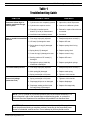
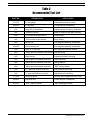
1
®
Authorized Dealer
SERVICE & REPAIR MANUAL
Cousteau/ SEA
First Stage Regulator
Copyright © 2000 Aqua Lung America, Inc.
Contents
Introduction .................................................................................................... 1
Warnings, Cautions, & Notes ........................................................................................... 1
Scheduled Service ........................................................................................................... 1
General Guidelines ........................................................................................................... 1
Initial Inspection Procedure .......................................................................... 2
External Inspection ........................................................................................................... 2
Immersion/ Leak Test........................................................................................................ 2
Intermediate Pressure Test ............................................................................................... 3
Disassembly Procedures ............................................................................... 4
Disassembly of Yoke Connection ...................................................................................... 6
Disassembly of DIN Connection ....................................................................................... 7
Reassembly Procedures................................................................................ 8
Reassembly of Yoke Connection .................................................................................... 10
Reassembly of DIN Connection ..................................................................................... 10
Final Adjustment and Testing Procedures ................................................. 12
Table 1 – Troubleshooting Guide ................................................................ 14
Table 2 – Recommended Tool List .............................................................. 15
Table 3 – Standard Parts Replacement Schedule ..................................... 16
Table 4 – Torque Specifications .................................................................. 17
Table 5 – Test Bench Specifications ........................................................... 17
Procedure A – Cleaning & Lubrication....................................................... 18
Table A – Recommended Lubricants & Cleaners ...................................... 19
Schematic – Cousteau/ SEA First Stage .................................................... 20
Schematic – EAN Configuration ................................................................. 21
Copyright ©2000 Aqua Lung America, Inc.
Service & Repair Manual - Cousteau/ SEA First Stage Regulator
Introduction
GENERAL GUIDELINES
1.
This manual provides factory prescribed procedures for the service and repair of the Cousteau/
SEA first stage regulator. It is not intended to be
used as an instructional manual for untrained personnel. The procedures outlined within this manual are
to be performed only by personnel who have received factory authorized training through an Aqua
Lung Service & Repair Seminar.
If you do not completely understand all of the
procedures outlined in this manual, contact Aqua
2.
Lung to speak directly with a Technical Advisor
before proceeding any further.
Warnings, Cautions, & Notes
Pay special attention to information provided in
warnings, cautions, and notes that are accompanied
by one of these symbols:
A WARNING indicates a procedure or situation
that may result in serious injury or death if
instructions are not followed correctly.
3.
4.
A CAUTION indicates any situation or technique that will result in potential damage to the
product, or render the product unsafe if instructions are not followed correctly.
A NOTE is used to emphasize important
points, tips, and reminders.
Scheduled Service
5.
Regulators should be given the same care and
maintenance as life support equipment. It is therefore important to perform scheduled overhaul service
for the Cousteau/ SEA, complete with second stages,
according to the procedures outlined in this manual; 6.
at least once a year with normal or infrequent use.
NOTE: A unit that receives heavy or frequent
use, such as in rental, instruction, or commer7.
cial applications, should be serviced at least
twice each year - or more often - depending on
the conditions of use and the manner in which
it is maintained. (Refer to the care and maintenance procedures outlined in the Regulator
Owner’s Manual.)
In order to correctly perform the procedures
outlined in this manual, it is important to follow
each step exactly in the order given. Read over
the entire manual to become familiar with all
procedures before attempting to disassemble or
service the Cousteau/ SEA first stage, and to
learn which specialty tools and replacement
parts will be required. Keep the manual open
beside you for reference while performing each
procedure. Do not rely on memory.
All service and repair should be carried out in a
work area specifically set up and equipped for
the task. Adequate lighting, cleanliness, and
easy access to all required tools are essential for
maintaining a professional repair facility.
Before beginning any disassembly, it is important to first perform the Initial Inspection procedure, and refer to Table 1 - Troubleshooting to
determine the possible cause of any symptoms
which may be present.
As each individual regulator is disassembled,
reusable components should be segregated to
prevent them from mixing with non-reusable
parts or parts from other regulators. Delicate
parts, and those which contain critical sealing
surfaces, must be protected and isolated from
other parts to prevent damage during the cleaning procedure.
Use only genuine Aqua Lung parts purchased
directly from Aqua Lung when servicing any
Aqua Lung product. Substitution with another
manufacturer’s parts constitutes an after-market
modification of the product, and renders the
original warranty null and void.
Do not attempt to reuse mandatory replacement
parts under any circumstances, regardless of the
amount of use the product has received since it
was manufactured or last serviced.
When reassembling, it is important to follow
every torque specification prescribed in this
manual, using a quality torque wrench. Most
parts are made of either marine brass or plastic,
and can be permanently damaged by undue
stress caused by overtightening.
Cousteau/ SEA First Stage Service & Repair Manual
2
Initial Inspection Procedure
EXTERNAL INSPECTION
1. Visually inspect the sintered filter to check for any signs that
contaminants may have entered the system, such as moisture,
rust, aluminum oxide, or charcoal.
NOTE: A green discoloration positively indicates that moisture has entered the regulator, and internal corrosion is
therefore likely to be found in the first stage. A white or rust
colored residue usually indicates that the regulator has been
used with a corroded aluminum or steel cylinder. Advise the
customer of the proper methods for maintaining the regulator, and the possible need to obtain service for their cylinder.
2.
Slide back the hose protector(s) to inspect the condition of the
LP hose at its fittings and along its length. Check closely for
any signs of blistering or abrasion, or corrosion of the fittings.
3.
Closely examine the finish of the first stage to check for any
scratches, dents, or other signs of damage to the plated finish.
CAUTION: Do not clean any parts which show damage to
their plated finish inside an ultrasonic cleaner. Ultrasonic
vibration may cause further damage to the finish.
4.
Closely examine all other parts of the first stage for any other
signs of external damage or corrosion.
5.
If present, examine the external diaphragm of the DRY
environmental protection kit to determine whether moisture
has entered the sealed chamber above the main diaphramg.
IMMERSION/ LEAK TEST
1. While the regulator is fully assembled and connected to a
second stage, connect the first stage to a cylinder that is filled
with 3,000 psi. Check to ensure there are no open ports or
hoses, and slowly open the cylinder valve to pressurize the
regulator. If obvious leakage occurs, including freeflow from
the second stage, shut off the air supply and proceed directly
to the section titled, Disassembly Procedures.
2. If leakage cannot be heard, or if the source of leakage detected audibly is not obvious, immerse the entire system in
fresh water and observe closely for up to one minute to check
for the formation of bubbles. Pay particularily close attention
to the area of the spring retainer, and to all hoses along their
length and at their fittings on both ends.
4.
Locate the source of any leakage found and refer to Table 1 –
Troubleshooting to determine its possible cause.
5.
Turn the cylinder valve shut and depress the second stage
purge button to depressurize the regulator before performing
the next procedure.
© 2000 Aqua Lung America, Inc.
Cousteau/ SEA First Stage Service & Repair Manual
3
INTERMEDIATE (OVER-BOTTOM) PRESSURE TEST
1.
Depress the second stage purge button once again to ensure
that the system is not pressurized. Connect the intermediate
pressure test gauge either to a quick-disconnect inflator hose,
or to the female fitting of a second stage IP hose, depending
on the connector of the test gauge.
NOTE: Whenever possible, Aqua Lung strongly recommends that a fully assembled and properly adjusted second
stage should be connected to the first stage before pressurizing to test intermediate pressure. This will provide a safety
relief valve in the event that the intermediate pressure exceeds 155-170 psi.
CAUTION: If a second stage is not connected to the first
stage, turn the bleed valve knob of the test gauge counterclockwise to ensure that it is open before pressurizing.
Failure to relieve intermediate pressure in excess of 400 psi
may result in damage to the test gauge or rupture of the IP
hose.
2.
Slowly open the valve of the supply cylinder only as far as
necessary to pressurize the first stage. While closely monitoring the IP test gauge to ensure that the intermediate pressure
does not rise above 200 psi, slowly turn the knob of the bleed
valve clockwise until it is completely shut.
CAUTION: If a second stage is not connected to the first
stage and the intermediate pressure continues to rise above
200 psi, immediately reopen the bleed valve of the test
gauge and shut the valve of the supply cylinder. Proceed
directly to perform the Disassembly Procedures, outlined in
the next section.
3.
Note the intermediate (over-bottom) pressure indicated by the
test gauge, and briefly purge the second stage or open and
shut the bleed valve of the test gauge to ensure that lockup is
achieved without “creeping” or fluctuating back and forth.
4.
If the intermediate pressure “creeps” up or otherwise fluctuates after cycling the regulator, wait for it to stabilize (if
possible) before making a final note of the intermediate
pressure.
NOTE: Correct intermediate pressure for the Cousteau/ SEA
first stage is 135 (±5) psi, with an inlet pressure of 3,000 psi.
5.
Turn the cylinder valve shut and depress the second stage
purge button to depressurize the system before attempting to
perform any disassembly.
© 2000 Aqua Lung America, Inc.
Cousteau/ SEA First Stage Service & Repair Manual
4
Disassembly Procedures
NOTE: Before performing any disassembly, refer to Table 3,
which references all mandatory replacement parts. These
parts must be replaced with new, and must never be reused regardless of the age of the regulator or how much use it has
received since it was last serviced.
CAUTION: To prevent damage to critical sealing surfaces,
use only a plastic or brass O-ring removal tool (P/N 9440-22)
when removing O-rings. Once an O-ring sealing surface has
been damaged, the part must be replaced with new in order
to prevent the possibility of leakage. DO NOT use a dental
pick, or any other type of steel instrument.
1.
Before disassembling the first stage, remove the low pressure
second stage hoses with a b" open-end wrench, and the low
pressure inflator hose with a b" or 2" open-end wrench.
Remove the high pressure hose with a s" open-end wrench,
or the high pressure port plug with a 4mm hex key. Remove
and discard the O-rings from the male fittings of each hose.
2.
Install a vise mounting tool (P/N 1003-95) or a discharged
C02 cartridge (P/N 7039-09) connected to a HP port adapter
(P/N 1020-85) into the HP port of the first stage body(10).
WARNING: DO NOT use a C02 cartridge which has not
been discharged. Doing so may cause the cartridge to
rupture, possibly resulting in serious personal injury.
3.
Secure the vise mounting tool inside a bench vise so that the
first stage is positioned standing vertical outside the vice with
the spring retainer and adjustment screw facing straight up.
(See Fig. 1.)
NOTE: If a “DRY” Environmental Protection Kit has not been
installed on the first stage, proceed directly to step 5. If an
Environmental Protection Kit has been installed, disassemble according to steps 4a-4c, outlined below:
4a. Mate an environmental diaphragm retainer wrench (P/N
0812-47) into the slots on both sides of the external diaphragm retainer(36). While holding the tool securely in
place, turn the diaphragm retainer counter-clockwise to
loosen and remove.
4b. Remove the external diaphragm(35) from either the diaphragm retainer or the spring retainer(32). Discard the
diaphragm, and do not attempt to reuse.
4c. Remove the environmental piston(33), and inspect it closely
to check for any signs of stress or other damage. Discard the
piston if it is found to be damaged, or set it aside if it is in
reusable condition. Replace the decal(34) as needed.
© 2000 Aqua Lung America, Inc.
Fig. 1
Cousteau/ SEA First Stage Service & Repair Manual
5
5.
Apply a 8mm hex key to the adjustment screw(31), and turn
the screw counter-clockwise to loosen and remove from the
spring retainer.
6.
Lift out the washer(30) and spring(29). Examine the spring
with the use of a magnifier, checking closely for any signs of
pitting, rusting, or other corrosion which permeates the
surface of the metal. Set the spring and washer aside if they
are in reusable condition, or replace with new as needed.
CAUTION: If permanent corrosion is found, discard the
spring and DO NOT attempt to reuse. A damaged or badly
corroded spring may seriously impair first stage performance
by failing to provide stable intermediate pressure.
7.
Apply a 30mm open end wrench to the spring retainer(28), or
use a 34mm open end wrench for the “DRY” version spring
retainer(32), and turn the retainer counter-clockwise to loosen
and remove from the first stage body.
8.
Lift the spring pad(27) and thrust washer(26b) out of the first
stage body. Discard the thrust washer and do not reuse.
9.
Using a 4mm hex key, install spare LP port plugs(23) into
three of the four LP ports, leaving one LP port open while the
other ports are sealed.
10. Direct a short burst of low pressure (50 psi) air through the
primary LP port to partially dislodge the diaphragm(26a)
from the first stage body (see Fig. 2). Lift out the diaphragm
and discard. Remove the port plugs that were installed in the
previous step.
Fig. 2
CAUTION: DO NOT attempt to pry the diaphragm out of the
first stage with a metal instrument. Doing so will permanently damage the seating shoulder in the first stage, requiring replacement of the body.
11. Loosen the vise to remove the first stage, and turn it over to
allow the pin support(25) and pin(24) to drop onto the bench.
12. Resecure the first stage in the vise with the high pressure side
facing straight up. Apply a 8mm hex key to the end plug(19),
and turn the plug counter-clockwise to loosen and remove
from the body. Remove and discard the O-ring(18), and set
the end plug aside.
13. Loosen the vise to remove the first stage, and carefully turn
the body over to allow the springs(14b & 14a), spring
block(17), and high pressure seat(13) to drop out onto the
bench. Discard the seat, and do not attempt to reuse.
14. Closely inspect both springs to check for any signs of corrosion that may have resulted from moisture entering the first
stage. If corrosion is found on either spring, discard and do
not reuse.
© 2000 Aqua Lung America, Inc.
Cousteau/ SEA First Stage Service & Repair Manual
6
16. Carefully remove the O-ring(15) and backup ring(16) from
inside the balancing chamber of the spring block, using a
brass or plastic O-ring removal tool to prevent any damage to
the internal sealing surface of the spring block.
17. With the use of a magnifier, closely examine the sealing
surface inside the balancing chamber of the spring block to
check for any signs of permanent corrosion, scoring, or other
damage. If found, discard the spring block and do not reuse.
CAUTION: The slightest scratch or scar across the sealing
surface inside the spring block may cause leakage, and
could prevent the regulator from achieving a stable lock-up of
intermediate pressure.
18. Using the seat extraction tool (P/N 1094-36), press the
crown(11) out of the first stage body by inserting the pin
through the low pressure side (see Fig. 3). Carefully pull the
crown out of the body, being careful to prevent damage to the
sealing surfaces inside the body and on the raised edge of the
crown. Remove and discard the O-ring(12).
19. Closely inspect the sealing surface inside the bore of the first
stage body to ensure that is perfectly smooth and free of any
scratches or other blemishes. If the body shows these signs of
damage or serious corrosion, it must be replaced with new
and cannot be reused.
20. Using a magnifier, closely examine the crown seating surface
to check for any signs of scratches, nicks, or other blemishes.
If found, discard the crown and do not attempt to reuse.
21. Resecure the vise mounting tool in the vise so that the first
stage is positioned standing outside the vice with either the
yoke or DIN connector facing straight up.
NOTE: Before proceeding, determine whether the first stage
is configured with a DIN or yoke connection, and refer to the
appropriate disassembly procedure provided below.
22. Disassembly of Yoke Connection
A. Remove the yoke screw(1) and untie the dust cap(2) from
the yoke(8). Remove and discard the dust cap O-ring(3).
B. Apply a 26mm open end wrench to the inlet fitting(7).
Using firm, steady force, turn the inlet fitting counterclockwise to loosen and remove from the first stage body.
Lift the inlet fitting and yoke straight off the inlet boss,
and set the yoke aside.
CAUTION: It is important that the wrench is securely seated
over the entire hex surface of the inlet fitting to prevent any
damage to the part. Do not use impact to loosen.
© 2000 Aqua Lung America, Inc.
Fig. 3
Cousteau/ SEA First Stage Service & Repair Manual
7
C. While holding the inlet fitting secure, apply a pair of
circlip pliers (P/N 1111-00) to the circlip(4) and squeeze
the circlip until it has disengaged from the yoke retainer.
Remove the circlip from the inlet fitting, along with the
filter(5) and both O-rings(6&9). Discard the filter and Orings, and do not reuse.
Disassembly of DIN Connection
A. Unscrew the thread protector cap and remove it from the
first stage.
B. Apply a 4mm hex key to the filter retainer(8a), and turn it
counter-clockwise to loosen and remove from the inlet
fitting(8e). Remove and discard both O-rings(8b&8c).
C. Apply a 19mm open end wrench to the hex feature of the
inlet fitting, and turn the inlet fitting counter-clockwise to
loosen and remove from the first stage body. Remove
and discard the O-ring(8f) and the filter disc(8d).
D. Closely inspect the threaded portion of the handwheel to
ensure it is free of any burrs or other damage that could
prevent proper threading. Replace the handwheel if
damage is found, or set it aside to be reused.
This concludes the disassembly of the Cousteau/ SEA
First Stage. Refer directly to Procedure A and Table A,
titled Cleaning & Lubrication, before proceeding to the
Reassembly Procedures.
© 2000 Aqua Lung America, Inc.
Cousteau/ SEA First Stage Service & Repair Manual
8
Reassembly Procedures
NOTE: Before performing any reassembly, it is important to
inspect all parts, both new and those that are being reused,
to ensure that every part and component is perfectly clean
and free of any dust, corrosion, or blemishes. Before dressing each O-ring with Christo-Lube®, check to ensure it is
clean, supple, and free of any blemish.
WARNING: Use only genuine Aqua Lung parts, subassemblies, and components whenever assembling any Aqua Lung
product. DO NOT attempt to substitute an Aqua Lung part
with another manufacturer’s, regardless of any similarity in
shape, size, or appearance. Doing so may render the product unsafe, and could result in serious injury or death.
1.
Install the O-ring(12) onto the crown(11), and place the crown
over the pin of the extractor tool (P/N 1094-36) with the
orifice sealing surface facing up.
2.
While holding the first stage body(10) vertical with the high
pressure side facing straight up, insert the handle of the
extractor tool into the body. Pass the tool through the low
pressure side so that the crown remains inside, resting above
its seating shoulder (see Fig. 4).
3.
Insert the handle of the extractor tool into the high pressure
side of the body once again, and press the crown into place so
that it fits snugly over the seating shoulder.
4.
Turn the body over and stand it on a padded surface with the
high pressure side facing down. Place the small end of the
pin support(25) inside the opening in the center of the body.
5.
Lay the diaphragm(26a) inside the body, and gently tamp it
down below the threads until it is seated evenly on all sides.
6.
Lay the thrust washer(26b) inside the body, and tamp it down
below the threads until it is evenly seated over the diaphragm.
7.
Lay the spring pad(27) in the center of the diaphragm with the
mating tab facing up, and thread the spring retainer(28 or 32)
clockwise into the body by hand until snug.
8.
Install a vise mounting tool (P/N 1003-95), or a discharged
C02 cartridge (P/N 7039-09) connected to a HP port adapter
(P/N 1020-85), into the HP port of the first stage body.
WARNING: DO NOT use a C02 cartridge which has not
been discharged. Doing so may cause the cartridge to
rupture, resulting in serious personal injury.
9.
Secure the vise mounting tool in a vise so the first stage
stands vertical with the spring retainer facing up. Apply a
torque wrench with 30mm crow-foot, or use a 34mm crow
foot for the “D” environmental version spring retainer, and
© 2000 Aqua Lung America, Inc.
Fig. 4
Cousteau/ SEA First Stage Service & Repair Manual
9
tighten the spring retainer to a torque measurement of 20 (±2)
foot-lbs.
10. Check to ensure that the spring pad is positioned over the
center of the diaphragm, and place the main spring(29) over
the spring pad inside the spring retainer. Then lay the
washer(30) on top of the spring.
Fig. 5a
Fig. 5b
11. Mate the adjustment screw(31) over the spring and washer,
and turn it clockwise to engage the threads of the spring
retainer. Apply a 8mm hex key to turn the adjustment screw
to its appropriate preliminary setting, depending on whether it
will assembled in the standard configuration, or with the “D”
environmental protection kit.
a.
Standard Spring Retainer – Turn the adjustment screw clockwise until it is exactly flush with the top of the spring retainer
(see Fig. 5a).
b.
“D” Environmental Spring Retainer – Turn the adjustment
screw clockwise until it is exactly flush with the internal
shoulder, above the female threads (see Fig. 5b).
When the adjustment screw has been set at its preliminary
adjustment, loosen the vise to remove the first stage.
NOTE: Do not proceed further with the assembly of the “D”
environmental protection kit at this time. Instructions for final
assembly follow the section titled, Final Adjustment & Testing
Procedures.
Fig. 6a
12. While holding the high pressure seat(13) by its stem, insert
the pin(24) into the center opening. Hold the first stage above
the pin with the high pressure side facing down, and carefully
align the end of the pin with the opening of the crown inside
(see Fig. 6a). Gently guide the pin and seat into the first stage
body so that the pin passes through the crown and into the
bottom of the pin support, which can be sighted through one
of the low pressure ports (see Fig. 6b). When the pin is
securely seated between the pin support and high pressure
seat, turn the fist stage over and stand it on a padded surface
with the high pressure side facing up.
CAUTION: Be careful to avoid damaging the polished
sealing surface of the crown when installing the pin and high
pressure seat. Excessive force or carelessness may otherwise scratch or nick the crown, and require it to be replaced.
13. Insert the backup ring(16) into the high pressure spring
block(17), and gently tamp it into place with a non-metallic
probe so that it is seated evenly and flat inside. Then, generously lubricate and install the O-ring(15) into the spring
block, directly over the backup ring.
Fig. 6b
© 2000 Aqua Lung America, Inc.
Cousteau/ SEA First Stage Service & Repair Manual
10
NOTE: If the backup ring is an earlier version that is black
with a concave surface on one side, it is important to install it
into the spring block with the concave side facing up, towards
the O-ring.
14. Insert the seat spring(14a) and open end of the spring block
assembly into the body, over the stem of the high pressure
seat. Then place the shorter seat spring(14b) directly over the
top of the spring block assembly.
15. Install the O-ring(18) onto the end plug(19), and mate the end
plug into the body, directly over the spring and spring block
assembly. Turn the end plug clockwise by hand until snug.
16. Resecure the vise mounting tool in the vise so the first stage
stands vertical with the end plug facing up. Apply a torque
wrench with 8mm hex key socket, and tighten the end plug to
a torque measurement of 45 (±2) inch-lbs.
17. Loosen the vise to remove the first stage, and refer to the
procedures below for assembling the yoke or DIN connection.
18. REASSEMBLY OF YOKE CONNECTION
A. Install the O-ring(6) into the recessed groove inside the
inlet fitting(7).
B. Install a new filter(5) into the yoke retainer with the
conical portion facing downward, and press it firmly into
place so that it seats inside the O-ring. Using internal
circlip pliers, install a circlip(4) to secure the filter.
NOTE: Install the circlip with the flat side facing up to ensure
greater holding strength.
C. Mate the inlet fitting through the yoke(8) and into the
inlet of the first stage body. Tighten clockwise by hand
until snug.
D. Secure the vise mounting tool in a vise so that the first
stage is horizontal and the yoke faces up (see Fig. 7).
Apply a torque wrench with 26mm crow-foot to tighten
the yoke retainer to a torque measurement of 20 (±2)
foot-lbs. Loosen the vise to remove the first stage, and
remove the vise mounting tool.
E. Install the O-ring(3) into the dust cap(2). Wrap the cord
that is tied to the dust cap around one leg of the yoke, and
pass the cap through the loop to form a loose knot.
F. Mate the yoke screw into the top of the yoke, and turn it
clockwise to fasten the dust cap snugly in place over the
inlet boss.
19. REASSEMBLY OF DIN CONNECTION
A. Install the O-ring(8f) onto the inlet fitting, and mate the
inlet fitting through the handwheel(8g), and into the inlet
of the first stage body. Turn the inlet fitting clockwise by
hand until snug.
© 2000 Aqua Lung America, Inc.
Fig. 7
Cousteau/ SEA First Stage Service & Repair Manual
11
B. Lay the filter disc(8d) flat inside the top of the inlet
fitting, with the coarser surface facing up.
C. Install the O-ring(8c) onto the filter retainer(8a), and mate
the filter retainer into the top of the inlet fitting. Tighten
clockwise until finger snug.
D. Secure the vise mounting tool in a vise so that the first
stage is horizontal and the yoke faces up. Apply a torque
wrench with 19mm hex socket to the inlet fitting and
tighten clockwise to a torque value of 22 foot-lbs (±2).
E. Apply a torque wrench with 4mm hex key socket to the
filter retainer and tighten clockwise to a torque measurement of 15 foot-lbs (±2).
F. Loosen the vise to remove the first stage, and remove the
vise mounting tool.
G. Install the O-ring(8b) into the groove at the top of the
inlet fitting, and fasten the DIN protective cap over the
DIN connection.
20. Install all O-rings(20&22) onto all hoses and port
plugs(21&23). Install all LP and HP hoses and port plugs
into the body, and tighten the port plugs clockwise until snug.
Apply a torque wrench with respective crow foot to tighten
each hose to a torque measurement of 40 (±5) inch-pounds.
WARNING: Be certain not to install a low pressure hose into
the high pressure port via an adapter. Doing so may cause
the hose to rupture when pressurized, and could result in
serious personal injury.
This concludes the reassembly of the Cousteau/ SEA
first stage regulator. Refer directly to the following
section, titled Final Adjustment & Testing.
© 2000 Aqua Lung America, Inc.
Cousteau/ SEA First Stage Service & Repair Manual
12
Final Adjustment and Testing Procedures
1.
Connect the intermediate pressure test gauge either to a
quick-disconnect inflator hose, or to the female fitting of a
second stage LP hose, depending on the connection of the test
gauge. Check to ensure there are no open ports.
CAUTION: Before testing intermediate pressure, it is important to connect the first stage to a fully assembled and
properly adjusted second stage. This will provide a safety
relief valve if the intermediate pressure exceeds 155-170 psi.
If a properly adjusted second stage is not available, be sure
to open the bleed valve of the test gauge before pressurizing.
Failure to relieve intermediate pressure in excess of 400 psi
may result in damage to the test gauge or LP hose.
2.
Check to ensure that the first stage adjustment screw(31) is
correctly set to its preliminary adjustment; flush with the top
of the standard spring retainer(28), or flush with the shoulder
inside the environmental spring retainer(32).
3.
Connect the first stage to a filtered air source of 500 psi, and
slowly pressurize the first stage. While closely monitoring
the IP test gauge to ensure that the intermediate pressure does
not rise above 120 psi, slowly turn the knob of the bleed valve
clockwise until it is completely shut.
CAUTION: If a second stage is not connected to the first
stage and the intermediate pressure rises above 200 psi,
immediately reopen the bleed valve of the test gauge and
shut off the air supply. Refer directly to Table 1 - Troubleshooting, and remedy as needed before proceeding further.
4.
When the intermediate pressure has stabilized below 120 psi,
apply a 8mm hex key to turn the adjustment screw clockwise
in small increments of adjustment. While turning the adjustment screw, it is important to simultaneously purge the second stage or briefly turn the test gauge bleed valve open and
shut. Monitor the test gauge while adjusting in this manner
until the intermediate pressure locks up between 115-120 psi.
CAUTION: Failure to cycle the regulator during adjustment
can result in a false reading of the intermediate-pressure.
5.
When the intermediate pressure has been determined to be
stable at 120 psi or less, increase the inlet pressure to between
2,500 – 3,000 psi while checking the IP test gauge once again
to ensure that the intermediate pressure does not rise above
135 psi. If the intermediate pressure rises above 135 psi,
immediately purge the second stage, or re-open the bleed
valve of the test gauge, and shut off the air supply. Refer
directly to Table 1 - Troubleshooting, and remedy as needed.
© 2000 Aqua Lung America, Inc.
Cousteau/ SEA First Stage Service & Repair Manual
13
6.
Repeat the adjustment procedure in step 4 to adjust the
Cousteau/ SEA first stage intermediate pressure to exactly
135 psi. Repeatedly purge the second stage or open and shut
the test gauge bleed valve at least 15 times to ensure that the
intermediate pressure locks up consistently and remains stable
at 135 (±5) psi, with no signs of creeping or fluctuation.
7.
Final Assembly – “DRY” Environmental Kit
a. While the regulator is still pressurized with 2,500 – 3,000
psi, insert the stem of the piston(33) into the hex opening
of the adjustment screw.
b. Lay the external diaphragm(36) inside the external diaphragm retainer(36), and tamp it down past the threads to
ensure that it seats evenly against the sealing surface.
c. Mate the external diaphragm retainer onto the spring
retainer, and apply the retainer wrench (P/N 0812-47) to
tighten it clockwise until completely snug.
d. Cycle the regulator to ensure that the intermediate pressure has not dropped below 135 psi. If necessary, depressurize the regulator and disassemble the environmental kit
to reset the intermediate pressure, and repeat steps 6-7.
After performing the overhaul and adjustment procedures
outlined in the Aqua Lung Service & Repair Manual provided
for the second stage, connect the first and second stage regulators to perform the following tests:
8.
9.
External Leak Test – Connect the regulator to a cylinder
which contains 2,500 - 3,000 psi, and open the cylinder valve
to pressurize the system. Submerge the cylinder and regulator
in a test tank of fresh water, and observe closely for up to one
minute to check for the formation of bubbles. If a steady
stream of bubbles is present, the system must be disassembled
at the source to check sealing surfaces, assembly sequence,
and component positioning in order to correct the problem(s).
NOTE: Extremely small leaks may be better detected by
applying a soap solution or Snoop™ to the leak area.
Bubble streams will indicate the source of the leak. Before
disassembling to correct any leaks, rinse the entire regulator
thoroughly with fresh water and blow out all residual moisture with filtered, low-pressure (30 psi) air. Disassemble and
remedy the problem, referring to Table 1 – Troubleshooting.
10. Subjective Breathing Test – Depress the second stage purge to
ensure that the volume of airflow is adequate to clear the
second stage. Then, breathe deeply from the mouthpiece. A
properly serviced and adjusted regulator should deliver a
smooth, uninterrupted airflow upon deep inhalation; without
excessive effort, hesitation, or freeflow. If any abnormalities
or problems occur, refer to Table 1 – Troubleshooting.
This concludes the annual service procedures for the
Cousteau/ SEA First Stage.
© 2000 Aqua Lung America, Inc.
Cousteau/ SEA First Stage Service & Repair Manual
14
Table 1
Troubleshooting Guide
SYMPTOM
Restricted airflow/ high inhalation resistance through
entire system.
High or unstable intermediate
pressure
Low intermediate pressure
External air leakage
(Immersion Test)
POSSIBLE CAUSE
TREATMENT
1. Cylinder valve not completely opened.
1. Open valve, check fill pressure.
2. Cylinder valve requires service.
2. Connect to a different cylinder.
3. Filter(8d) is installed upside
down or (5 or 8d) is contaminated.
3. Reinstall or replace filter with new
as needed.
4. Insufficient intermediate pressure.
4. See below.
1. First-stage improperly adjusted.
1. Readjust adjustment screw(31).
2. HP seat(13) damaged or worn.
2. Replace HP seat.
3. Spring block O-ring(15) damaged
or worn.
3. Replace spring block O-ring.
4. Spring block(17) damaged.
4. Replace spring block.
5. Crown O-ring(12) damaged or worn.
5. Replace crown O-ring.
6. Sealing surface of HP crown(11)
damaged.
6. Replace HP crown.
7. Springblock springs(14a&14b)
weakened or damaged.
7. Replace springblock springs.
1. First-stage improperly adjusted.
1. Readjust adjustment screw(31).
2. Main spring(29) damaged.
2. Replace main spring.
3. Spring retainer(28 or 32) loose.
3. Tighten to 20±2 foot-lbs.
1. Spring retainer(28 or 32) loose.
1. Tighten to 20±2 foot-lbs.
2. Diaphragm(26a) worn or damaged.
2. Replace diaphragm.
3. Diaphragm seating surface inside
first stage body(10) damaged.
3. Replace first stage body.
NOTE: This is a partial list of possible problems and recommended treatments. For
more information, refer to the second-stage troubleshooting guide, or contact the
Technical Services Department for assistance with problems not described here.
CAUTION: Recommended treatments which require disassembly of the regulator
must be performed during a complete overhaul, according to the prescribed procedures for scheduled, annual service. Do not attempt to perform partial service.
© 2000 Aqua Lung America, Inc.
Cousteau/ SEA First Stage Service & Repair Manual
15
Table 2
Recommended Tool List
PART NO.
DESCRIPTION
APPLICATION
1116-10
I.P. test gauge
Intermediate pressure testing
9440-22
O-ring tools
O-ring removal & installation
N/A
Magnifier w/ illumination
Sealing surface and spring inspection
N/A
Ultrasonic cleaner
Brass & stainless steel parts cleaning
N/A
0-120 inch-lbs torque wrench
Small fittings
N/A
10-50 foot-lbs torque wrench
Large fittings
N/A
Bench vise
First stage disassembly/ reassembly
Vise mounting tool
First stage disassembly/ reassembly
N/A
4mm or 5⁄32" hex key
Port plugs and DIN filter retainer
N/A
19mm open-end wrench & hex socket
DIN inlet fitting
N/A
8mm hex key
Adjustment screw & end plug
N/A
26mm open-end wrench/ crow-foot
Yoke inlet fitting
N/A
30mm open-end wrench/ crow-foot
Spring retainer
N/A
34mm open-end wrench/ crow-foot
"DRY" spring retainer
N/A
9
Low pressure hose fitting
N/A
58
High pressure hose fitting
1111-00
Snap ring pliers
Removal and installation of filter circlip
1094-36
Extraction tool
Crown removal & installation
0812-47
"DRY" retainer wrench
"DRY" diaphragm retainer
1003-95
⁄16" open-end wrench/ crow-foot
⁄ " open-end wrench/ crow-foot
© 2000 Aqua Lung America, Inc.
Cousteau/ SEA First Stage Service & Repair Manual
16
Table 3
Standard Parts Replacement Schedule
PART NUMBER
DESCRIPTION
KEY NUMBER
QTY
8200-94
O-ring
3
1
8630-51
Circlip
4
1
1068-29
Filter
5
1
8200-14
O-ring
6
1
8244-08
O-ring
9
1
8200-38
O-ring
12
1
1059-40
High Pressure Seat
13
1
8200-80
O-ring
15
1
8280-05
Backup Ring
16
1
8244-07
O-ring
18
1
9570-04
O-ring
20
2
8200-11
O-ring
22
4
1034-25
Diaphragm w/ Washer
26
1
1063-37
Environmental Diaphragm
39
1
© 2000 Aqua Lung America, Inc.
Cousteau/ SEA First Stage Service & Repair Manual
17
Table 4
Torque Specifications
PART NUMBER
DESCRIPTION / KEY NUMBER
TORQUE
1063-39
Inlet Fitting/ (7)
20 (±2) ft-lbs
1063-32
DIN Filter Retainer/ (8a)
15 (±2) ft-lbs
1063-33
DIN Inlet Fitting/ (5f)
22 ±2 ft-lbs
1063-24
Spring Retainer/ (32)
20 ±2 ft-lbs
1063-17
"DRY" Spring Retainer/ (36)
20 ±2 ft-lbs
1063-27
End Plug/ (19)
45 ±2 ft-lbs
1063-03
Port Plug / (21) or HP Hose
20 (±2) inch-lbs
1063-04
Port Plug / (23) or LP Hose
20 (±2) inch-lbs
Table 5
Test Bench Specifications
TEST
CONDITION
ACCEPTABLE RANGE
Leak test
Inlet 2,500-3,000 psi
None
Intermediate pressure
Inlet 2,500-3,000 psi
135 (±5) psi
Intermediate pressure creep Inlet 2,500-3,000 psi
5 psi max between 5 to 15 seconds
after cycling regulator (purge)
Opening effort
Inlet 2,500-3,000 psi,
intermediate pressure 135 (±5) psi
+0.8 to +1.4 inch H20
Flow effort
Intermediate pressure 135 (±5) psi
at 10 SCFM
+6 inches H20 (maximum)
Purge flow
Intermediate pressure 135 (±5) psi
5.0 SCFM flow rate (minimum)
© 2000 Aqua Lung America, Inc.
Cousteau/ SEA First Stage Service & Repair Manual
18
Procedure A
Cleaning & Lubrication
(All Aqua Lung Regulators)
1. Acid Bath - Aqua Lung strongly recommends ChromeSafe™ regulator cleaner (P/N 0201-05) for cleaning all reusable brass and stainless steel parts. ChromeSafe™ is a specially formulated cleaner that does
not harm rubber or Teflon parts, yet effectively removes silicone grease, corrosion, and grime from metal
parts, leaving only a brilliant shine. For best results, soak parts in an ultrasonic cleaner for 5 to 15
minutes, unless the chrome finish is chipped or flaking. Parts with damage to their chrome finish should
be cleaned separately outside the ultrasonic cleaner to avoid agitation. Be certain to isolate more delicate
parts, such as orifice cones, to prevent damage to sealing surfaces.
CAUTION: Harsh acids, such as muriatic acid, may cause damage to parts and must be strictly
avoided. White vinegar, although less effective, is one suitable substitute for ChromeSafe™.
CAUTION: Ultrasonic cleaning times in excess of 15 minutes may damage the chrome finish of certain
parts. Be certain to use a timer, and do not leave parts unattended while cleaning.
NOTE: Although ChromeSafe™ contains a degreasing agent, cleaning heavily greased parts in
ChromeSafe™ will shorten the effective life of the solution, and require it to be replaced on a more
frequent basis. Heavily greased parts may be degreased in a solution of warm water and mild dish
detergent prior to being placed in the acid bath.
2. Fresh Water Rinse - If tap water is extremely “hard,” distilled water may be used to prevent any mineral
residue. Remove parts from the acid bath and place directly into this rinse. Agitate lightly, and allow to
soak for 5-10 minutes. Remove and blow dry with low pressure (25 psi) filtered air, and inspect closely
to ensure proper cleaning and like-new condition.
ANODIZED ALUMINUM, PLASTIC & RUBBER PARTS
Anodized aluminum parts and parts made of plastic or rubber, such as box bottoms, box tops, dust caps,
etc., may be soaked and cleaned in a solution of warm water mixed with mild dish soap. Use only a soft
nylon toothbrush to scrub away any deposits. Thoroughly blow dry, using low pressure filtered air.
HOSES
If buildup of corrosion is severe, it is permissible to soak only the hose fittings in ChromeSafe™ cleaner
as needed, and not allow any solution to enter the hose. Rinse in fresh water and allow to dry with the
cleaned ends hanging down. Blow filtered air through them prior to installing onto the regulator.
LUBRICATION AND DRESSING
All O-rings should be lubricated with either Christo-Lube® (preferred for high pressure systems) or Dow
Corning® 111 food grade silicone grease . Dress the O-rings with a very light film of grease, and remove
any visible excess by running the O-ring between thumb and forefinger. Avoid applying excessive
amounts of silicone grease, as this will attract particulate matter that may cause damage to the O-ring.
Hoses and other black rubber parts may be dressed and preserved using a clean cloth impregnated with a
pump silicone milk.
CAUTION: Aerosol spray silicone must be strictly avoided. Do not attempt to use as a substitute for
silicone grease.
CAUTION: Do not apply any form of silicone lubricant to silicone rubber parts, as this will cause them
to deteriorate prematurely.
© 2000 Aqua Lung America, Inc.
Cousteau/ SEA First Stage Service & Repair Manual
19
Table A
Recommended Lubricants & Cleaners
(All Aqua Lung Regulators)
LUBRICANT / CLEANER
APPLICATION
SOURCE
Christo-Lube®
All O-rings seals; cylinder valve threads
(preferred for high pressure DIN systems)
Lubrication Technologies
310 Morton Street
Jackson, OH 45640
(614) 286-2644
Dow Corning® 111
(pure silicone grease)
All O-ring seals
Dow Corning Corp.
P.O. Box 1767-T
Midland, MI 48640
800-248-2481
CAUTION: Silicone rubber requires no lubrication or preservative treatment. DO NOT
apply silicone grease or spray to silicone rubber parts. Doing so will cause a chemical
breakdown and premature deterioration of the material.
Silicone Pump™
(non-aerosol silicone milk spray)
General preservative/conditioner for
hoses, instrument console boots, etc.
McNett Corp.
P.O. Box 996
Bellingham, WA 98227
800-221-7325
CAUTION: Aerosol spray silicone should be avoided because (1) common aerosol
propellants may attack plastic and rubber parts, and (2) because only a slight amount
of silicone remains after the solvent evaporates, and provides no lasting benefit.
Anti-Seize Lubricant #80208
M.A.S. cylinder adapter - female threads
Micra ADJ adjustment screw
Permatex Industrial Corp.
705 N. Mountain Rd.
Newington, CT 06111
(860) 520-5000
ChromeSafe™
(ultrasonic cleaning solution)
Degreaser and acid bath for reusable
stainless steel and brass parts.
Aqua Lung P/N 0201-05
(1 quart)
Oakite #31
Acid bath for reusable stainless
steel and brass parts.
Oakite Products, Inc.
50 Valley Road
Berkeley Heights, NJ 07922
White distilled vinegar
(100 gr.)
Acid bath for reusable stainless
steel and brass parts.
"Household" grade
CAUTION: DO NOT use muriatic acid for the cleaning of any parts. Muriatic acid,
even when strongly diluted, can harm chrome plating, and may leave a residue that is
harmful to O-ring seals and other parts.
Liquid dishwashing detergent
(diluted with warm water)
Degreaser for brass and stainless steel parts,
general cleaning solution for plastic, rubber,
and anodized aluminum parts.
"Household" grade
Snoop™
Leak testing
Nupro Company
400 E. 345th St.
Willoughby, OH 44094
440-951-7100
© 2000 Aqua Lung America, Inc.
Cousteau/ SEA First Stage Service & Repair Manual
20
Cousteau/ SEA First Stage
2
36
35
3
1
33
4
5
32
31
30
29
34
6
7
8a
30
8b
28
8c
8d
31
29
8e
8
8f
8g
9
10
27
11
13 12
24
25
26b
26a
14a
19
18
14b
15
17 16
22
23
20
21
Key # Part #
----- 1005-11
----- 1005-21
----- 9000-00
1 ----- 1075-07
2 ----- 1031-14
3 ----- 8200-94
4 ----- 8630-51
5 ----- 1068-29
6 ----- 8200-14
7 ----- 1063-39
8 ----- 1068-42
9 ----- 8244-08
10 ---- 1063-22
11 ---- 1060-27
12 ---- 8200-38
13 ---- 1059-40
14 ---- 1015-09
15 ---- 8200-80
16 ---- 8280-05
17 ---- 1015-65
18 ---- 8244-07
19 ---- 1063-27
20 ---- 9570-04
Description
First Stage, Cousteau, Yoke
First Stage, Cousteau Dry, Yoke
Overhaul Parts Kit
Yoke Screw
Dust Cap
O-ring
Circlip
Filter
O-ring
Inlet Fitting
Yoke
O-ring
Body
Crown
O-ring
HP Seat
Spring Kit (includes 14a & 14b)
O-ring
Backup Ring
Spring Block
O-ring
End Plug
O-ring
© 2000 Aqua Lung America, Inc.
Key # Part #
21 ---- 1063-03
22 ---- 8200-11
23 ---- 1063-04
24 ---- 1063-23
25 ---- 1060-22
26 ---- 1034-25
27 ---- 1017-29
28 ---- 1063-24
29 ---- 1063-56
30 ---- 8450-97
31 ---- 1060-26
Description
Port Plug, HP
O-ring
Port Plug, LP
Pin
Pin Support
Diaphragm w/ Thrust Washer
Spring Pad
Spring Retainer
Spring
Washer
Adjustment Screw
Used with "Dry" Environmental Kit
----- 1005-25
32 ---- 1063-17
33 ---- 1063-19
34 ---- 1063-38
35 ---- 1063-37
36 ---- 1063-18
Dry Environmental Kit, Complete
Spring Retainer, Dry
Piston
Decal
External Diaphragm
Diaphragm Retainer
Part numbers in BOLD ITALICS indicate standard overhaul
replacement part.
Cousteau/ SEA First Stage Service & Repair Manual
21
Cousteau/ SEA
(EAN Configuration)
3
4
38
5
37
1
35
6
7
31
34
32
36
33
8
2
31
32
33
30
9
10
11
12
15
21
20
16b
19
18 17
14
29
13
26
16a
27
28
*NOTE: Parts purchased individually for use in any
Aqua Lung EAN product must be cleaned and inspected
according to the procedures outlined in the Enriched Air
Cleaning & Service Manual, Doc. #9002-08. O-rings are
included with the Overhaul Parts Kit, and may not be
ordered individually.
24
25
22
23
Key # Part #
----- 1041-71
----- 1041-51
----- 9002-06
1 ----- 1063-94
2 ----- 1075-06
3 ----- 1073-28
4 ----- n/a*
5 ----- 8630-51
6 ----- 1068-29
7 ----- n/a*
8 ----- 1063-39
9 ----- 1073-11
10 ---- n/a*
11 ---- 1073-24
12 ---- 1063-22
13 ---- 1060-27
14 ---- n/a*
15 ---- 1059-40
16 ---- 1015-09
17 ---- n/a*
18 ---- 8280-05
19 ---- 1015-65
20 ---- n/a*
21 ---- 1063-27
Description
First Stage, Cousteau, EAN
First Stage, Cousteau Dry, EAN
Overhaul Parts Kit (pre-cleaned & sealed)
Decal, EAN
Yoke Screw
Dust Cap, Green
O-ring (EAN)
Circlip
Filter, Conical
O-ring (EAN)
Inlet Fitting
Yoke
O-ring (EAN)
Color Ring, EAN
Body
Crown
O-ring (EAN)
HP Seat
Spring Kit (includes 16a & 16b)
O-ring (EAN)
Back-up Ring
Spring Block
O-ring (EAN)
Plug
Key # Part #
22 ---- n/a*
23 ---- 1063-03
24 ---- n/a*
25 ---- 1063-04
26 ---- 1063-23
27 ---- 1060-22
28 ---- 1034-25
29 ---- 1017-28
30 ---- 1063-24
31 ---- 1063-56
32 ---- 8450-97
33 ---- 1060-26
Description
O-ring (EAN)
Port Plug, High Pressure
O-ring (EAN)
Port Plug, Low Pressure
Pin
Pin Support
Diaphragm w/ Thrust Washer
Spring Pad
Spring Retainer
Main Spring
Washer, Main Spring
Adjustment Screw
Used with "Dry" Environmental Kit
----- 1005-25
34 ---- 1063-17
35 ---- 1063-19
36 ---- 1063-38
37 ---- 1063-37
38 ---- 1063-18
Dry Environmental Kit, Complete
Spring Retainer
Piston
Decal
External Diaphragm
Diaphragm Retainer
Part numbers in BOLD ITALICS indicate standard overhaul
replacement part.
© 2000 Aqua Lung America, Inc.
2340 Cousteau Court
Vista, California 92083
Phone (760) 597-5000
Fax (760) 597-4900
www.aqualung.com