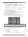
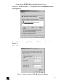
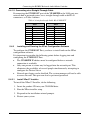
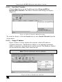
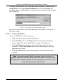
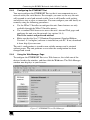
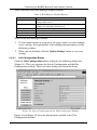
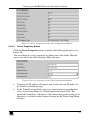
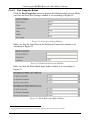
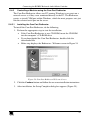
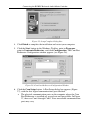
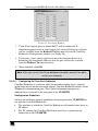
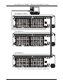
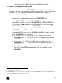
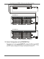
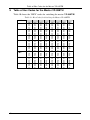
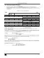
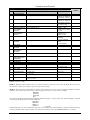
1
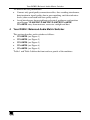
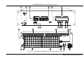
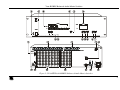
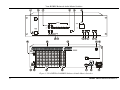
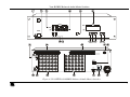
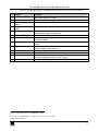
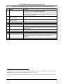
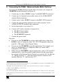
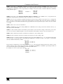
Kramer Electronics, Ltd.
USER MANUAL
Models:
VP-88ETH, 8x8 RGBH / Balanced Audio Matrix Switcher
VP-84ETH, 8x4 RGBH / Balanced Audio Matrix Switcher
VP-82ETH, 8x2 RGBH / Balanced Audio Matrix Switcher
VP-66ETH, 6x6 RGBH / Balanced Audio Matrix Switcher
VP-64ETH, 6x4 RGBH / Balanced Audio Matrix Switcher
Contents
Contents
1
2
3
4
5
5.1
5.2
5.3
5.4
Introduction
Getting Started
Overview
Your RGBH / Balanced Audio Matrix Switcher
Connecting the RGBH / Balanced Audio Matrix Switcher
Connecting the Balanced/Unbalanced Stereo Audio Input/Output
Controlling via RS-232 (for example, using a PC)
Controlling via RS-485
Setting the ETHERNET Port and Utilities
1
1
2
3
11
13
14
15
16
5.4.1
5.4.2
5.4.3
5.4.4
5.4.5
5.4.6
Connecting the VP-88ETH Ethernet Port
Installing and Running the XPort Configuration Software
Configuring the ETHERNET Port
Using the Web Manager Page
Controlling a Machine using the Com Port Redirector
Using the Com Port Redirector
16
18
21
21
25
31
5.5
Setting the VP-88ETH Dipswitches
31
5.5.1
Setting the SELF ADDRESS Dipswitches
32
5.6
5.7
6
6.1
6.2
6.3
Setting the Reply Dipswitch
Setting the RS-232\RS-485 Dipswitch
Operating Your VP-88ETH Machine
Displaying the Unit Characteristics
Selecting and Connecting an Output and/or Input
Choosing the Audio-Follow-Video or Breakaway Option
32
32
33
33
33
34
6.3.1
6.3.2
Setting the Audio-Follow-Video Option
Setting the Breakaway Option
34
34
6.4
Confirming Settings
34
6.4.1
6.4.2
Toggling between the At Once and Confirm Modes
Confirming a Switching Action
35
35
6.5
Storing/Recalling Input/Output Configurations
36
6.5.1
6.5.2
6.5.3
Storing an Input/Output Configuration
Recalling an Input/Output Configuration
Deleting an Input/Output Configuration
36
36
36
6.6
6.7
7
7.1
7.2
7.3
8
9
10
Resetting the Machine
Using the TERM: 75 /TTL Buttons
Controlling Several RGBHV / Balanced Audio Matrix Switchers
Control Configuration via RS-232 and RS-485
Control Configuration via RS-485
Control Configuration via the ETHERNET Port
Technical Specifications
Table of Hex Codes for the Master VP-88ETH
Communication Protocol
36
37
37
37
39
40
41
42
43
i
Contents
Figures
Figure 1: VP-88ETH 8x8 RGBHV / Balanced Audio Matrix Switcher
Figure 2: VP-84ETH 8x4 RGBHV / Balanced Audio Matrix Switcher
Figure 3: VP-82ETH 8x2 RGBHV / Balanced Audio Matrix Switcher
Figure 4: VP-66ETH 6x6 RGBHV / Balanced Audio Matrix Switcher
Figure 5: VP-64ETH 6x4 RGBHV / Balanced Audio Matrix Switcher
Figure 6: Connecting the VP-88ETH 8x8 RGBHV / Balanced Audio Matrix Switcher
Figure 7: Connecting the Balanced Stereo Audio Input/Output
Figure 8: Connecting the Unbalanced Stereo Audio Output
Figure 9: Connecting an Unbalanced Source to the Balanced Input
Figure 10: Connecting a PC without using a Null-modem Adapter
Figure 11: Controlling via RS-485 (for example, using an RC-3000)
Figure 12: Local Area Connection Properties Window
Figure 13: Internet Protocol (TCP/IP) Properties Window
Figure 14: XPort™ Installer Main Dialog Box
Figure 15: Device Found on the Network
Figure 16: IP Address Assignment Dialog Box
Figure 17: ETHERNET Port Web-Manager
Figure 18: Server Configuration in the Unit Configuration Window
Figure 19: Port Configuration in the Unit Configuration Window
Figure 20: Server Properties in the Unit Configuration Window
Figure 21: Serial Port Settings Window
Figure 22: Dedicated Connection Window
Figure 23: Flush Mode Input Buffer Window
Figure 24: Com Port Redirector Welcome Screen
Figure 25: Setup Complete Dialog Box
Figure 26: Com Port Redirector Configuration Window
Figure 27: Port Setup Window
Figure 28: IP Service Setup Dialog Box
Figure 29: Port Settings Window
Figure 30: Silent Mode Checked in the RDCfg Window
Figure 31: VP-88ETH Dipswitches
Figure 32: Control Configuration via RS-232 and RS-485
Figure 33: Control Configuration via RS-485
4
5
6
7
8
12
13
13
13
14
15
17
17
19
19
20
21
22
23
23
24
24
24
25
26
26
27
28
29
30
31
38
40
Tables
Table 1: The RGBH / Balanced Audio Matrix Switcher Front Panel Features
Table 2: The RGBH / Balanced Audio Matrix Switcher Rear Panel Features
Table 3: Crossover Cable RJ-45 PINOUT
Table 4: Straight-through Cable RJ-45 PINOUT
Table 5: Web Manager Window Buttons
Table 6: Port Settings Description
Table 7: Dipswitch Settings
Table 8: MACHINE # Dipswitch Settings
Table 9: Technical Specifications of the RGBH / Balanced Audio Matrix Switchers
Table 10: Hex Codes for Switching the Master VP-88ETH
Table 11: Protocol Definitions
ii
9
10
16
18
22
29
31
32
41
42
43
KRAMER: SIMPLE CREATIVE TECHNOLOGY
Introduction
1
Introduction
Welcome to Kramer Electronics (since 1981): a world of unique, creative and
affordable solutions to the infinite range of problems that confront the video,
audio and presentation professional on a daily basis. In recent years, we have
redesigned and upgraded most of our line, making the best even better! Our
350-plus different models now appear in 8 Groups1, which are clearly defined
by function.
Congratulations on purchasing your Kramer RGBH / Balanced Audio Matrix
Switcher2, which is ideal for presentation and production applications. The
package includes the following items:
VP-88ETH/VP-84ETH/VP-82ETH/VP-66ETH/VP-64ETH RGBH /
Balanced Audio Matrix Switcher
Power cord and Null-modem adapter
Windows®-based Configuration Manager XPort software and Com Port
Redirector
Windows®-based Kramer control software3
This user manual4
2
Getting Started
We recommend that you:
Unpack the equipment carefully and save the original box and packaging
materials for possible future shipment
Review the contents of this user manual
Use Kramer high performance high resolution cables5
1 GROUP 1: Distribution Amplifiers; GROUP 2: Video and Audio Switchers, Matrix Switchers and Controllers; GROUP 3:
Video, Audio, VGA/XGA Processors; GROUP 4: Interfaces and Sync Processors; GROUP 5: Twisted Pair Interfaces;
GROUP 6: Accessories and Rack Adapters; GROUP 7: Scan Converters and Scalers; and GROUP 8: Cables and Connectors
2 Available in the following models: VP-88ETH (an 8x8 model), VP-84ETH (an 8x4 model), VP-82ETH (an 8x2 model),
VP-66ETH (a 6x6 model), and/or VP-64ETH (a 6x4 model)
3 Downloadable from our Web site at http://www.kramerelectronics.com
4 Download up-to-date Kramer user manuals from our Web site at http://www.kramerelectronics.com
5 The complete list of Kramer cables is on our Web site at http://www.kramerelectronics.com
1
Overview
3
Overview
The high performance VP-88ETH/VP-84ETH/VP-82ETH/VP-66ETH/
VP-64ETH RGBH / Balanced Audio Matrix Switcher is designed for highresolution computer graphics signals and balanced stereo audio signals. Each
machine is a true matrix, routing any input to any or all outputs
simultaneously.
In particular, the RGBH / Balanced Audio Matrix Switcher:
Consists of three large bandwidth video channels, Red, Green and Blue
(RGB) and two TTL (logic level) channels – Horizontal and Vertical sync
Switches channels during the vertical interval, offering glitch free
transitions when sources share a common reference sync
Provides Audio breakaway, for switching audio independently from video
Offers preset memory locations for quick access to common
configurations
Includes the TAKE button, which lets you place multiple switches in a
queue and then activate them with one touch of this button
Can be used for mixed applications such as Y/C and YUV simultaneously
Includes an ETHERNET connection that supports easy dial-up and Internet
system remote control (requiring only a dedicated IP address1 and a modem in
the remote location) whether it is a stand-alone PC or a LAN2 system
Control the VP-88ETH/VP-84ETH/VP-82ETH/VP-66ETH/VP-64ETH
using the front panel buttons, or remotely via:
RS-485 or RS-232 serial commands transmitted by a touch screen system,
PC, or other serial controller
ETHERNET
The Kramer RC-IR1 Infra-Red Remote Control Transmitter3
The VP-88ETH/VP-84ETH/VP-82ETH/VP-66ETH/VP-64ETH is
dependable, rugged and fits into three vertical spaces (3U) of a standard 19"
rack.
1 IP Address is a 32-binary digit number that identifies each sender or receiver (within a network via a particular server or
workstation) of data (HTML pages or e-mails) that is sent in packets across the Internet. Every device connected to an IP
network must have a unique IP address. This address is used to reference the specific unit
2 LAN is Local Area Network
3 Previously known as the IR-1/IR-1-01
2
KRAMER: SIMPLE CREATIVE TECHNOLOGY
Your RGBH / Balanced Audio Matrix Switcher
To achieve the best performance:
Connect only good quality connection cables, thus avoiding interference,
deterioration in signal quality due to poor matching, and elevated noiselevels (often associated with low quality cables)
Avoid interference from neighboring electrical appliances and position
your Kramer VP-88ETH/VP-84ETH/VP-82ETH/VP-66ETH/
VP-64ETH away from moisture, excessive sunlight and dust
4
Your RGBH / Balanced Audio Matrix Switcher
This section describes each switcher as follows:
VP-88ETH (see Figure 1)
VP-84ETH (see Figure 2)
VP-82ETH (see Figure 3)
VP-66ETH (see Figure 4)
VP-64ETH (see Figure 5)
Table 1 and Table 2 define the front and rear panels of the machines.
3
Your RGBH / Balanced Audio Matrix Switcher
Figure 1: VP-88ETH 8x8 RGBHV / Balanced Audio Matrix Switcher
4
KRAMER: SIMPLE CREATIVE TECHNOLOGY
Your RGBH / Balanced Audio Matrix Switcher
Figure 2: VP-84ETH 8x4 RGBHV / Balanced Audio Matrix Switcher
5
Your RGBH / Balanced Audio Matrix Switcher
Figure 3: VP-82ETH 8x2 RGBHV / Balanced Audio Matrix Switcher
6
KRAMER: SIMPLE CREATIVE TECHNOLOGY
Your RGBH / Balanced Audio Matrix Switcher
Figure 4: VP-66ETH 6x6 RGBHV / Balanced Audio Matrix Switcher
7
Your RGBH / Balanced Audio Matrix Switcher
Figure 5: VP-64ETH 6x4 RGBHV / Balanced Audio Matrix Switcher
8
KRAMER: SIMPLE CREATIVE TECHNOLOGY
Your RGBH / Balanced Audio Matrix Switcher
Table 1: The RGBH / Balanced Audio Matrix Switcher Front Panel Features
#
Feature
1
IR Receiver
2
3
5
POWER switch
OUTPUT SELECTOR
Buttons
INPUT SELECTOR
Buttons
TAKE
6
7
INPUT STATUS display
RCL Button
8
STO Button
9
AFV Button
10
11
12
AUDIO Button
VIDEO Button
OFF Button
13
ALL Button
4
Function
The red LED is illuminated when receiving signals from the Kramer InfraRed remote control transmitter
Illuminated switch for turning the unit ON or OFF
Select the output to which the input is switched
Select the input to switch to the output
Press to toggle between the Confirm mode1 and the At Once mode (user
confirmation per action is unnecessary)
Displays the selected input switched to the output (marked above each input)
2
Press the RCL button followed by an INPUT button to recall a setup from the
non-volatile memory
Press the STO button followed by an INPUT button2 to store the current
settings
When pressed3, actions relate to the video and audio channels. The audio
channels follow the video channels
When pressed3, actions relate to audio
When pressed3, actions relate to video
An OFF-OUTPUT combination disconnects that output from the inputs; an
OFF-ALL combination disconnects all the outputs
Press ALL followed by an INPUT button to connect that input to all the outputs
1 When in the Confirm mode, the TAKE button blinks
2 In this case the INPUT button corresponds to the setup address number
3 The button illuminates
9
Your RGBH / Balanced Audio Matrix Switcher
Table 2: The RGBH / Balanced Audio Matrix Switcher Rear Panel Features
#
Feature
Function
14
TERM: 75 /TTL Buttons
15
17
18
19
20
AUDIO INPUTS Terminal
Block Connectors
AUDIO OUTPUTS1 Terminal
Block Connectors
RS-485 Port
Ethernet Connector
Power Connector with Fuse
Dipswitches
21
22
23
24
RS-232 DB 9F Port
OUT BNC Connectors
INPUTS BNC Connectors
EXT./IN 1 Button
25
EXT. SYNC BNC Connector
16
1
When both buttons are released, the upper input channels are used for
TTL level H & V sync signals (RGBHV operation);
When both buttons are pushed in, the input channels become analog video
channels, just as the lower RGB channels, and the machine can be used
for 5 identical video channels
Connect to the balanced stereo audio sources
Connect to the balanced stereo audio acceptors
Pin G is for the Ground connection2; pins B (-) and A (+) are for RS-485
Connects to the PC or other Serial Controller through computer networking
AC connector, enabling power supply to the unit
Dipswitches for setup of the unit (1, 2 and 3 are for setting the machine
number; 4 is for RS-485 bus termination; 5 is for Reply; 8 is for RS-485 PC
communication)
Connects to the PC or the remote controller
Connect to the video acceptors
Connect to the video sources
When pushed in selects an external sync from the external source; when
released selects the internal sync (inputted via the video input #1
connectors)
Connects to the external sync source
1 VP-88ETH has 8 inputs and 8 outputs; VP-84ETH has 8 inputs and 4 outputs; VP-82ETH has 8 inputs and 2 outputs;
VP-66ETH has 6 inputs and 6 outputs; VP-64ETH has 6 inputs and 4 outputs
2 The ground connection is sometimes connected to the shield of the RS-485 cable. In most applications, the ground is not
connected
10
KRAMER: SIMPLE CREATIVE TECHNOLOGY
Connecting the RGBH / Balanced Audio Matrix Switcher
5
Connecting the RGBH / Balanced Audio Matrix Switcher
To connect the RGBH / Balanced Audio Matrix Switcher, for example the
VP-88ETH, do the following1(see Figure 6):
1. Connect up to 8 video / RGBHV sources2 to the BNC INPUT connectors3.
2. Connect up to 8 balanced stereo audio sources to the AUDIO INPUT
terminal block connectors.
3. Connect up to 8 video / RGBHV acceptors to the BNC OUT connectors3.
4. Connect the corresponding balanced stereo audio acceptors4 to the
AUDIO OUTPUTS terminal block connectors.
5. Set the dipswitches (see section 5.5).
6. Connect a PC and/or controller (if required) to:
The RS-232 port and/or
The RS-485 port and/or
The ETHERNET connector
7. Connect the power cord4.
Note that:
You can use the VP-88ETH for various video applications (other than
RGBHV) such as Composite video, Y/C, YUV (Component video) and
even SD – SDI signals (Serial Digital Video)
You can use the VP-88ETH for parallel applications. For example, you
can use it simultaneously as a composite video, 8x8 matrix and a
Component (YUV) Matrix
When using the VP-88ETH in mixed applications (such as Y/C and YUV
simultaneously), select the parallel output channels for the same format,
for example, if the Red and Green Channels are used for Y/C (the Red for
“Y” and the Green for “C”) then the output channels should be used
similarly (Red for “Y” and Green for “C”)5
1 Switch off the power on each device before connecting it to your VP-88ETH. After connecting your VP-88ETH, switch on
its power and then switch on the power on each device
2 All signal connections using more than one cable to interconnect between the devices, should be of equal length
3 5 BNC connectors (RGBHV) per source/acceptor
4 Not illustrated in Figure 6
5 In a mixed signal application all the input channels are selected simultaneously. For example, if used for Y/C and YUV
parallel switching, then when input number 1 is selected, it selects both input number 1 of the Y/C and input number 1 of the
YUV channel
11
Connecting the RGBH / Balanced Audio Matrix Switcher
Audio Connections
are not shown
RGBHV High Resolution
Graphics Source 1
RS-232
RGBHV
Projector
RGBHV
Display
RGBHV High Resolution
Graphics Source 6
Figure 6: Connecting the VP-88ETH 8x8 RGBHV / Balanced Audio Matrix Switcher
12
KRAMER: SIMPLE CREATIVE TECHNOLOGY
Connecting the RGBH / Balanced Audio Matrix Switcher
5.1 Connecting the Balanced/Unbalanced Stereo Audio Input/Output
This section illustrates how to wire:
A balanced input/output connection (see Figure 7)
An unbalanced audio input (see Figure 8)
An unbalanced source to the balanced input on the VP-88ETH (see Figure 9)
Figure 7 illustrates how to wire a balanced input/output connection:
L
+ G -
R
+ G -
Figure 7: Connecting the Balanced Stereo Audio Input/Output
Figure 8 illustrates how to wire an unbalanced acceptor to the balanced output
of the unit:
L
R
+ G - + G -
Figure 8: Connecting the Unbalanced Stereo Audio Output
Figure 9 illustrates how to connect an unbalanced source to the balanced input
on the VP-88ETH:
L
R
+ G - + G -
Figure 9: Connecting an Unbalanced Source to the Balanced Input
13
Connecting the RGBH / Balanced Audio Matrix Switcher
5.2 Controlling via RS-232 (for example, using a PC)
To connect a PC to the VP-88ETH unit1, using the Null-modem adapter
provided with the machine (recommended):
Connect the RS-232 DB9 rear panel port on the VP-88ETH unit to the
Null-modem adapter and connect the Null-modem adapter with a 9-wire
flat cable2 to the RS-232 DB9 port on your PC
To connect a PC to the VP-88ETH unit1, without using a Null-modem adapter:
Connect the RS-232 DB9 port on your PC to the RS-232 DB9 rear panel
port on the VP-88ETH unit, as Figure 10 illustrates2 (depending on
whether the PC has a 9-pin or 25-pin connector)
Figure 10: Connecting a PC without using a Null-modem Adapter
1 When connecting a single VP-88ETH unit via RS-232, set the SELF ADDRESS # dipswitches to SELF ADDRESS # 1,
according to Table 8
2 Up to 50 feet of cabling may be used for the RS-232 connection
14
KRAMER: SIMPLE CREATIVE TECHNOLOGY
Connecting the RGBH / Balanced Audio Matrix Switcher
5.3 Controlling via RS-485
You can control a VP-88ETH unit via an RS-485 controller1, for example, a
PC (equipped with an RS-485 interface) or a Master Programmable Remote
Control system, such as the Kramer RC-30002.
To connect an RC-3000 to a single VP-88ETH unit (see Figure 11):
1. Connect the RS-485 terminal block port on the RC-3000 to the RS-485
port on the VP-88ETH unit, as follows:
Connect the “A” (+) PIN on the RS-485 rear panel port of the
RC-3000 to the “A” (+) PIN on the RS-485 rear panel port of the
VP-88ETH unit
Connect the “B” (-) PIN on the RS-485 rear panel port of the
RC-3000 to the “B” (-) PIN on the RS-485 rear panel port of the
VP-88ETH unit
If shielded twisted pair cable is used, the shield may be connected to
the “G” (Ground) PIN on one of the units (for example, on the
RC-3000)
2. Set the SELF ADDRESS # dipswitches on the VP-88ETH unit to a
SELF ADDRESS # between 2 and 8, according to section 5.5.1. Do not
set as SELF ADDRESS # 1 (the Master). Terminate the RS-485 line on
both the VP-88ETH unit (set DIP 4 to ON) and on the RC-30003.
RS-485 PINOUT
G
_ B
KEYBOARD EXTENSION
OUT
IN
1 2 3 4 5 6 7 8 9 10 11 12 13 14 15 16
+ A
REMOTE CONTACT
1
2 3
4
5
6
7 8
G
RS-485
RS-232 IN
RS-232 OUT
12 VDC
Figure 11: Controlling via RS-485 (for example, using an RC-3000)
1 RS-485 can be used for control even for distances exceeding 1km
2 Previously known as the VS-3000
3 Refer to the RC-3000 user manual for details of how to terminate the RS-485 line
15
Connecting the RGBH / Balanced Audio Matrix Switcher
5.4 Setting the ETHERNET Port and Utilities
To control your VP-88ETH via the ETHERNET, do the following:
1. Connect the Ethernet port of the VP-88ETH to the LAN port of your PC
(see section 5.4.1).
2. Install and configure your ETHERNET Port (see sections 5.4.2 through
5.4.4).
3. Install the COM Port Redirector to control the VP-88ETH (see
section 5.4.5).
5.4.1
Connecting the VP-88ETH Ethernet Port
You can connect the ETHERNET port either via a crossover cable (see
section 5.4.1.1) or a straight through cable (see section 5.4.1.2).
5.4.1.1 Connecting via a Crossover Cable
Connect the ETHERNET port of the VP-88ETH to the LAN port on your PC,
via a crossover cable with RJ-45 connectors, as Table 3 defines.
Table 3: Crossover Cable RJ-45 PINOUT
Side 1
PIN
1
2
3
4
5
6
7
8
Wire Color
White-orange
Orange
White-green
Blue
White-blue
Green
White-brown
Brown
Side 2
PIN
1
2
3
4
5
6
7
8
Wire Color
White-green
Green
White-orange
Blue
White-blue
Orange
White-brown
Brown
This type of connection is recommended for identification of the factory
default IP Address of the VP-88ETH during the initial configuration
After connecting the ETHERNET port, configure your PC as follows:
1. Right-click the My Network Places icon on your desktop.
16
2.
Select Properties.
3.
Right-click Local Area Connection Properties.
4.
Select Properties.
The Local Area Connection Properties window appears.
KRAMER: SIMPLE CREATIVE TECHNOLOGY
Connecting the RGBH / Balanced Audio Matrix Switcher
5.
Select the Internet Protocol (TCP/IP) and click the Properties Button
(see Figure 12).
Figure 12: Local Area Connection Properties Window
6.
Select Use the following IP Address, and fill in the details as shown in
Figure 13.
7.
Click OK.
Figure 13: Internet Protocol (TCP/IP) Properties Window
17
Connecting the RGBH / Balanced Audio Matrix Switcher
5.4.1.2 Connecting via a Straight-Through Cable
If connecting the ETHERNET port of the VP-88ETH to the LAN port on a
network hub or network router, use a straight-through cable with RJ-45
connectors, as Table 4 defines:
Table 4: Straight-through Cable RJ-45 PINOUT
Side 1
PIN
1
2
3
4
5
6
7
8
5.4.2
Wire Color
White-orange
Orange
White-green
Blue
White-blue
Green
White-brown
Brown
Side 2
PIN
1
2
3
4
5
6
7
8
Wire Color
White-orange
Orange
White-green
Blue
White-blue
Green
White-brown
Brown
Installing and Running the XPort Configuration Software
To configure the ETHERNET Port, you have to install and run the XPort
configuration software.
It is important to consider the following points before logging into and
configuring the ETHERNET Port:
The VP-88ETH IP address must be configured before a network
connection is available
Only one person at a time may be logged into the network port. This
eliminates the possibility of several people simultaneously attempting to
configure the Device Server
Network port logins can be disabled. The system manager will not be able
to access the unit. This port can also be password protected
5.4.2.1
Install XPort™ Installer
To install the XPort™ Installer, do the following:
1. Insert the product CD into your CD-ROM drive.
2. Run the XPort installer setup.
3. Respond to the installation wizard prompts.
4. Restart your system.
18
KRAMER: SIMPLE CREATIVE TECHNOLOGY
Connecting the RGBH / Balanced Audio Matrix Switcher
5.4.2.2
Run XPort™ Installer
Click the Start button on the Task Bar and select Programs\XPort
Installer\XPort Installer. The XPort™ Installer main dialog box displays
(Figure 14).
Figure 14: XPort™ Installer Main Dialog Box
To search for devices, click the Search icon or select Search Network from the
Action menu.
5.4.2.3
Assign IP Address
Figure 15 shows a device found on the network, with the IP addresses
assigned at the factory. The Hardware Address is an individual permanent
address assigned to a particular device on the network. The Hardware Address
can be found on the product label inside the unit.
Note: Click on a device to view its attributes
Figure 15: Device Found on the Network
19
Connecting the RGBH / Balanced Audio Matrix Switcher
To change the IP address, first select the device from the list, then click the
Assign IP icon or select Assign IP Address from the Action menu. The
hardware address and IP address are loaded into the Assign IP Address dialog
box (Figure 16).
Figure 16: IP Address Assignment Dialog Box
Enter the new IP Address and click OK. The new IP Address will appear in
the main window.
5.4.2.4
Test the IP Address
To test the IP Address, do the following:
1. Select the device from the main window list.
2. Click the Ping icon or select Ping from the Action menu. The Ping
Device dialog box shows the IP Address of the selected device.
3. Click the Ping button and the results will be displayed in the Status
window. Use the Clear Status button to clear the window so you can
ping the device again.
4. Click the Close button to close the dialog box and return to the main
window.
Note: If you do not receive “Reply” messages, make sure the unit is
properly attached to the network and that the IP address assigned is valid
for the particular network segment you are working with. If you are not sure,
check with your Systems Administrator
20
KRAMER: SIMPLE CREATIVE TECHNOLOGY
Connecting the RGBH / Balanced Audio Matrix Switcher
5.4.3
Configuring the ETHERNET Port
You must configure the ETHERNET Port so that it can communicate on a
network with your serial device. For example, you must set the way the unit
will respond to serial and network traffic, how it will handle serial packets,
and when to start or close a connection. You can configure your unit locally or
remotely using the following procedures:
Use the XPort™ Installer to configure the unit. Some features are only
available through the XPort™ Installer menus
Use a standard Web browser to access the unit’s internal Web pages and
configure the unit over the network (see section 5.4.4)
This is the easiest and preferred method
Make sure that the Java™ 2 Runtime Environment (Standard Edition,
Version 1.4.1 or higher) software is installed on your PC. If not, download
it from: http://java.sun.com
The unit’s configuration is stored in non-volatile memory and is retained
without power. The unit performs a reset after the configuration has been
changed and stored.
5.4.4
Using the Web Manager Page
To configure the ETHERNET Port via a Web browser, first click one of the
devices listed in the window, and then click the Web icon. The Web-Manager
window now displays in your browser.
Figure 17: ETHERNET Port Web-Manager
21
Connecting the RGBH / Balanced Audio Matrix Switcher
Table 5 describes the Web Manager window buttons.
Table 5: Web Manager Window Buttons
Button
Function
Unit Configuration
Press to enter the Server Configuration and the Port Configuration
settings (section 5.4.4.1)
Server Properties
Press to enter the Server Properties and change the server properties
by editing any of the fields (section 5.4.4.2)
Port Properties
Press to enter the Port Properties and modify them
Factory Settings1
Press to set to factory default settings
Update Settings
Press to update settings
Channel 1
Disabled
When in the Web Manager window:
1. Use the menu buttons to navigate to sub pages where you can configure
server settings. See explanations of the configuration parameters in the
following sections.
2. When you are finished, click the Update Settings button to save your
settings.
5.4.4.1
Unit Configuration Button
Click the Unit Configuration button to display the following dialog box
(Figure 18). This page contains the Server Configuration and the Port
Configuration settings. These are static settings read from the device.
Figure 18: Server Configuration in the Unit Configuration Window
Figure 18 and Figure 19 show the information available in the Unit
Configuration window.
22
KRAMER: SIMPLE CREATIVE TECHNOLOGY
Connecting the RGBH / Balanced Audio Matrix Switcher
Figure 19: Port Configuration in the Unit Configuration Window
5.4.4.2
Server Properties Button
Click the Server Properties button to display the following dialog box (see
Figure 20).
You can change the server properties by editing any of the fields. Hold the
cursor over one of the fields to display Help messages.
Figure 20: Server Properties in the Unit Configuration Window
Changing the IP address will require you to enter the new IP address in
the browser to reload the page
In the Telnet Password field, enter a password to prevent unauthorized
access to the Setup Mode via a Telnet connection to port 9999. The
password is limited to 4 characters. (An enhanced password setting of 16
characters is available under Security Settings on the Telnet Setup Mode
window)
23
Connecting the RGBH / Balanced Audio Matrix Switcher
5.4.4.3
Port Properties Button
Click the Port Properties button to display the following dialog boxes. Make
sure that the Serial Port Settings window is set according to Figure 211.
Figure 21: Serial Port Settings Window
Make sure that the Local Port in the Dedicated Connection window is set
according to Figure 22.
Figure 22: Dedicated Connection Window
Make sure that the Flush Mode Input buffer window is set according to
Figure 23.
Figure 23: Flush Mode Input Buffer Window
1 You can change the server properties by selecting the desired properties from the drop down list
24
KRAMER: SIMPLE CREATIVE TECHNOLOGY
Connecting the RGBH / Balanced Audio Matrix Switcher
5.4.5
Controlling a Machine using the Com Port Redirector
The Com Port Redirector allows any PC running Windows to use ports on a
network server as if they were connected directly to the PC. The Redirector
creates a virtual COM port within Windows, which for most purposes acts just
like the selected serial port on the server.
5.4.5.1
Installing the Com Port Redirector
To install the Com Port Redirector, do the following:
1. Perform the appropriate step to start the installation:
If the Com Port Redirector is on a CD-ROM, insert the CD-ROM
into the computer’ s CD-ROM drive
If you downloaded the Com Port Redirector, double-click the
downloaded file
Either step displays the Redirector - Welcome screen in Figure 24
Figure 24: Com Port Redirector Welcome Screen
2. Click the Continue button and follow the on-screen installation instructions.
3. After installation, the Setup Complete dialog box appears (Figure 25).
25
Connecting the RGBH / Balanced Audio Matrix Switcher
Figure 25: Setup Complete Dialog Box
4. Click Finish to complete the installation and restart your computer.
5. Click the Start button in the Windows Taskbar, point to Programs,
point to Lantronix Redirector, and click Configuration. The Com Port
Redirector Configuration window appears (see Figure 26).
Figure 26: Com Port Redirector Configuration Window
6. Click the Com Setup button. A Port Setup dialog box appears (Figure
27), with the first logical communications port checked.
The physical communication ports on the computer where the Com
Port Redirector is installed are grayed-out and unavailable. In Figure
27, these are Com1 through Com3. Your unavailable communication
ports may vary
26
KRAMER: SIMPLE CREATIVE TECHNOLOGY
Connecting the RGBH / Balanced Audio Matrix Switcher
Figure 27: Port Setup Window
7. Click all the logical ports to which the PC will be redirected. A
checkmark appears next to each logical port selected. Each port selected
will be available from the Redirect To drop-down list in the Com Port
Redirector Configuration window (see Figure 26).
8. To deselect a port, click it again to remove the checkmark next to it.
Removing the checkmark indicates that the port will not be available
from the Redirect To drop-down list.
9. When finished, click OK.
Note: After you use the Port Setup dialog box to add or remove Com ports,
restart your computer
5.4.5.2
Configuring the Com Port Redirector
Com Port Redirector is a software utility for network-enabling legacy software
applications that do not have network support. Com Port Redirector installs virtual
Windows® communication ports. These virtual communication ports are
redirected over a network to the serial port of the VP-88ETH.
Configuration Guidelines
Observe the following general guidelines when preparing the VP-88ETH for
use with the Com Port Redirector:
The machine to which the Com Port Redirector will connect must have an
IP address
The PC running the Com Port Redirector must have a good network
connection to the VP-88ETH
27
Connecting the RGBH / Balanced Audio Matrix Switcher
If redirecting over a Wide Area Network (WAN), both the PC and the
VP-88ETH must have a correct gateway address configured in their
TCP/IP1 settings
Redirector Configuration
Before using the Com Port Redirector, you have to configure the VP-88ETH
Ethernet Port. To do so, do the following:
Assign a compatible IP address to the device server
Set the serial settings (baud rate, parity, flow control, data bits)
Set the port number to 10001 (recommended)
For specific instructions, see section 5.4.1.
To configure the Com Port Director:
1. Click the Start button in the Windows Taskbar, point to Programs,
point to Lantronix Redirector, and click Configuration. The Com Port
Redirector Configuration window appears (see Figure 26).
2. Using the Redirect To drop-down list at the top of the Com Port
Redirector Configuration window, click a redirected Com port.
3. Click the Add IP button. The IP Service Setup dialog box appears (see
Figure 28).
Figure 28: IP Service Setup Dialog Box
4. In the Host field, enter the IP address of the VP-88ETH.
5. In the TCPPort field, type 10001 for Channel 1 (according to the local
port, configured in the VP-88ETH unit).
6. Click OK.
1 TCP/IP is Transmission Control Protocol/Internet Protocol
28
KRAMER: SIMPLE CREATIVE TECHNOLOGY
Connecting the RGBH / Balanced Audio Matrix Switcher
7. Click the Port Settings button. The Port Settings dialog box appears.
Figure 29 shows the Port Settings dialog box and Table 6 describes its
settings.
8. Check Raw Mode.
Figure 29: Port Settings Window
9. Click OK.
10. Click the Save button (see Figure 26).
11. Click the Close button (see Figure 26).
Table 6: Port Settings Description
Setting
Description
Timeout Reconnect If checked, the Com Port Redirector re-establishes the connection if the connection
times out1
Server Reconnect
Inband Listen
If checked, the Com Port Redirector re-establishes the connection if the server closes it1
If checked, the Com Port Redirector uses the inband redirector protocol on inbound
connections from a VP-88ETH. This protocol allows settings like modem signals, baud
rate and parity to be exchanged between Com Port Redirector and the server.
Connection
Timeout
Specifies the maximum number of seconds that the Com Port Redirector waits for a
connection to be made before giving up on this attempt. If Timeout Reconnect is
enabled, each connection attempt lasts this long. If Timeout Reconnect is disabled, the
connection attempt fails after this interval and no more attempts are made.
Force v2 Protocol
N/A
No Net Close
If checked, prevents the network connection from being dropped when the
communications application is closed. To drop the connection, click the Disconnect
button in the Com Port Redirector Configuration window. This allows applications to
close and reopen ports, without waiting for the network connection to be reestablished
and negotiated.
1 When auto-reconnecting, the Com Port Redirector tries to reconnect until the connection succeeds or you click the Cancel
button in the pop-up connection dialog box. If the port was closed by the communications application or by clicking
Disconnect, the Com Port Redirector does not try to auto-reconnect
29
Connecting the RGBH / Balanced Audio Matrix Switcher
Setting
Raw Mode
Description
If checked, Raw Mode forms a raw TCP connection to the server’s serial port,
accelerating the connection between the communications application and the server,
without sending configuration or status information from the PC to the server. When
using Raw Mode, configure the Com Port Redirector and your VP-88ETH to use the
same port number
Verify Connectivity
After configuring the Com Port Redirector and the VP-88ETH, use a terminal
emulation program such as HyperTerminal to verify connectivity from the
Com Port Redirector to the VP-88ETH. To verify connectivity between the
Com Port Redirector and the VP-88ETH using HyperTerminal:
1. Click the Start button in the Windows Taskbar, point to Programs, point to
Accessories, point to Communications, and click HyperTerminal.
2. Open a new session to the virtual Com port configured to connect to the
device server.
3. When the HyperTerminal window opens, a pop-up window displays:
Attempting to connect to service.
If this message is replaced by: Successfully redirected to service, the
connection from the Com Port Redirector to the device server was
successful.
However, if the message is replaced by Failed to connect to any service,
the connection failed. Ensure your settings are correct.
4. To hide the pop-up window, check Silent Mode on the Com Port
Redirector Configuration window (Figure 30).
Figure 30: Silent Mode Checked in the RDCfg Window
30
KRAMER: SIMPLE CREATIVE TECHNOLOGY
Connecting the RGBH / Balanced Audio Matrix Switcher
5.4.6
Using the Com Port Redirector
Observe the following general guidelines when using the Com Port Redirector:
Do not run the Com Port Redirector with other software that installs a
virtual com port
Do not run the Com Port Redirector with other Com Port Redirection
software on the same PC
5.5 Setting the VP-88ETH Dipswitches
This section describes the machine set-up and dipswitch selection.
Figure 31 illustrates the factory default dipswitches and Table 7 describes
them.
OFF
ON
Figure 31: VP-88ETH Dipswitches
Table 7: Dipswitch Settings
DIPS
Function
Description
1, 2, 3
Self Address
Determines the position of the machine in the input expansion
configuration
4
RS-485 TERM
ON for RS-485 Line Termination
OFF for no RS-485 Line Termination
5
Reply
ON enables reply from switcher to PC
OFF disables reply from switcher to PC
6, 7
RESERVED
8
RS-232 \ RS-485
ON enables RS-232 communication between switcher and PC
OFF disables reply from switcher to PC
31
Connecting the RGBH / Balanced Audio Matrix Switcher
5.5.1
Setting the SELF ADDRESS Dipswitches
The SELF ADDRESS determines the position of a VP-88ETH unit in the
sequence, specifying which VP-88ETH unit is being controlled when several
VP-88ETH units are controlled by a PC or serial controller. Set the SELF
ADDRESS on a VP-88ETH unit via DIPS 1, 2, and 3, according to Table 8.
When using a stand-alone VP-88ETH unit, set the SELF ADDRESS to 1
When connecting more than one VP-88ETH unit, set the first machine
(the Master) connected via RS-232, as SELF ADDRESS # 1. The Master
connects to the PC via the RS-232 port. The other VP-88ETH slave units
(each set to a SELF ADDRESS # between 2 and 8) interconnect via their
RS-485 ports to the RS-485 port on the Master
Table 8: MACHINE # Dipswitch Settings
MACHINE #
DIPS
1
2
ON
ON
3
1 Master
2
ON
OFF
ON
ON
3
ON
OFF
ON
4
OFF
OFF
ON
5
ON
ON
OFF
6
OFF
ON
OFF
7
ON
OFF
OFF
8
OFF
OFF
OFF
5.6 Setting the Reply Dipswitch
Dipswitch #5 (the Reply dipswitch) enables or disables a reply from the
VP-88ETH to the PC.
This is desirable, so that the controlling device “ knows” that the controlled
device has carried out its instructions. When an RS-485 connection is used for
communication between the Matrix Switcher and the PC, dipswitch #8 should
be set to OFF. In some applications, it may be desirable for some machines
not to reply to instructions received on the RS-232 and RS-485 ports. In this
case, the Reply, or acknowledgement commands should be disabled.
5.7 Setting the RS-232\RS-485 Dipswitch
The RS-232\RS-485 dipswitch allows you to enable RS-232 communication
between the Matrix Switcher and the PC.
32
KRAMER: SIMPLE CREATIVE TECHNOLOGY
Operating Your VP-88ETH Machine
6
Operating Your VP-88ETH Machine
Operate your VP-88ETH via:
The front panel buttons
RS-232/RS-485 serial commands transmitted by a touch screen system,
PC, or other serial controller
ETHERNET
The Kramer RC-IR1 Infra-Red Remote Control Transmitter1
6.1 Displaying the Unit Characteristics
The VP-88ETH 7-segment Display2 shows the selected audio3 or video4 input
switched to the marked output.
The unit’ s characteristics5 are displayed in the following circumstances:
Immediately (and automatically) after switching on the power; and
When simultaneously pressing and holding for 3 seconds the INPUT buttons:
1, 2 and 3 (see section 6.6)
6.2 Selecting and Connecting an Output and/or Input
To switch an input to an output, press the desired OUTPUT button, followed by
the desired INPUT button.
In addition, to:
Disconnect a video/audio Input from a specific output, press the desired
OUTPUT button followed by the OFF button. To disconnect all the
outputs, press the ALL button, followed by the OFF button
Connect a video/audio input to all outputs, press the ALL button followed
by the INPUT button corresponding to the input that is to be routed to all
the outputs
1 Previously known as the IR-1/IR-1-01
2 Item 6 in Table 1
3 When the Audio button illuminates, that is, when the audio breakaway mode is selected
4 When the Video button illuminates, that is, when the video breakaway mode is selected
5 Machine model and software version
33
Operating Your VP-88ETH Machine
6.3 Choosing the Audio-Follow-Video or Breakaway Option
You can switch stereo audio signals in one of two ways, either:
Audio-follow-video (AFV), in which all operations relate to both the
video and the audio channels; or
Breakaway, in which video and audio channels switch independently
6.3.1
Setting the Audio-Follow-Video Option
To set the Audio-follow-video (AFV) option press the AFV button:
If the AUDIO and VIDEO configurations are the same, then the AFV
button illuminates. The audio will follow the video
If the AUDIO differs from the VIDEO, then the TAKE and the AUDIO
buttons will flash. Also, the audio outputs in the STATUS 7-segment
display, which will be changed, will flash1. Press the TAKE button to
confirm the modification. The audio will follow the video
6.3.2
Setting the Breakaway Option
To set the Breakaway option:
Press either the AUDIO (for audio control only) or the VIDEO (for video
control only) button:
If the AUDIO button illuminates, switching operations relate to Audio
If the VIDEO button illuminates, switching operations relate to Video
The STATUS window displays audio or video settings, according to your
selection.
6.4 Confirming Settings
You can choose to work in the At Once or the Confirm mode. When the
VP-88ETH operates in the At Once mode, pressing an OUTPUT-INPUT
combination implements the switch immediately. In the Confirm mode, the
TAKE button must be pressed to authorize the switch.
The At Once Mode
In the At Once mode, you save time as execution is immediate and actions
require no user confirmation. However, no protection is offered against
changing an action in error.
1 Warning that you are about to modify the audio configuration for AFV operation
34
KRAMER: SIMPLE CREATIVE TECHNOLOGY
Operating Your VP-88ETH Machine
The Confirm Mode
In the Confirm mode:
You can key-in several actions and then confirm them by pressing the
TAKE button, to simultaneously activate the multiple switches
Every action requires user confirmation, to protect against erroneous switching
Execution is delayed1 until the user confirms the action
6.4.1
Toggling between the At Once and Confirm Modes
To toggle between the At Once and Confirm modes, do the following:
1. Press the TAKE button to toggle from the At Once mode2 to the
Confirm mode3.
Actions now require user confirmation and the TAKE button illuminates.
2. Press the illuminated TAKE button to toggle from the Confirm mode
back to the At Once mode.
Actions no longer require user confirmation and the TAKE button no
longer illuminates.
6.4.2
Confirming a Switching Action
To confirm a switching action (in the Confirm mode), do the following:
1. Press an OUTPUT-INPUT combination.
The corresponding input number that is displayed in the STATUS
7-segment Display blinks. The TAKE button also blinks.
2. Press the blinking TAKE button to confirm the action.
The corresponding input number that is displayed in the STATUS
7-segment Display no longer blinks. The TAKE button illuminates.
To confirm several actions (in the Confirm mode), do the following:
1. Press each OUTPUT-INPUT combination in sequence.
The corresponding input numbers that are displayed in the STATUS
7-segment Display blink. The TAKE button also blinks.
2. Press the blinking TAKE button to confirm all the actions.
The corresponding input numbers that are displayed in the STATUS
7-segment Display no longer blink. The TAKE button illuminates.
1 Failure to press the TAKE button within one minute (the Timeout) will abort the action
2 The TAKE button does not illuminate
3 The TAKE button illuminates
35
Operating Your VP-88ETH Machine
6.5 Storing/Recalling Input/Output Configurations
You can store and recall up to 8 input/output1 configurations (or setups) in
non-volatile memory, using the INPUT SELECTOR buttons 1 to 8.
6.5.1
Storing an Input/Output Configuration
To store the current status in memory, do the following:
1. Press the STO button.
The STO button blinks.
2. Press one of the INPUT SELECTOR buttons from 1 to 8. This will be
the setup # in which the current status is stored.
The memory stores the data at that reference.
6.5.2
Recalling an Input/Output Configuration
To recall an input/output configuration, do the following:
1. Press the RCL button.
The RCL button blinks.
2. Press the appropriate INPUT SELECTOR button (the INPUT
SELECTOR button # corresponding to the setup #). The memory recalls
the stored data from that reference.
6.5.3
Deleting an Input/Output Configuration
To delete an input/output configuration, do the following:
1. Press the STO and RCL buttons simultaneously.
Both the STO and RCL buttons blink.
2. Press the appropriate INPUT SELECTOR button.
This erases that specific input/output configuration from the memory,
leaving it empty and available2.
6.6 Resetting the Machine
To reset the machine, press INPUT buttons 1, 2 and 3 simultaneously. The
machine resets itself and a 7-segment self-test is automatically performed.
1 For VP-88ETH, VP-84ETH and VP-82ETH, up to 8 input/output configurations; for VP-66ETH and VP-64ETH, up to 6
input/output configurations
2 Storing a new configuration over a previous configuration (without deleting it first) replaces the previous configuration
36
KRAMER: SIMPLE CREATIVE TECHNOLOGY
Controlling Several RGBHV / Balanced Audio Matrix Switchers
6.7 Using the TERM: 75 /TTL Buttons
In some graphics and multimedia applications, only 4 channels are used –
RGBS. The sync channel uses Composite Sync format (not separated to
Horizontal and Vertical), and is usually at analog signal levels (1 Volt
approx.). Composite sync channel is rarely of the TTL type.
Use the TERM. 75 /TTL buttons as follows:
Release both buttons when the matrix is to be used in an RGBHV application
Press the H channel button to the 75 position, when a Composite Analog
sync1 is used
Press both the H and the V TERM. buttons to the 75 position, when the
switcher is used for analog or SDI signals2
If this channel is not properly set up, damage may incur to the signal
source, acceptor or the Matrix!
7
Controlling Several RGBHV / Balanced Audio Matrix Switchers
You can connect up to eight single VP-88ETH units with control from a PC
or serial controller via RS-232 and RS-485, or up to seven single units via
RS-485.
7.1 Control Configuration via RS-232 and RS-485
To control up to eight VP-88ETH units – with control from a PC or serial
controller – via RS-232 and RS-485, as Figure 32 illustrates, do the following:
1. Connect the video sources and acceptors, the appropriate audio sources
and acceptors, and the power cord to each VP-88ETH unit.
2. On each VP-88ETH, set the SELF ADDRESS # as required3
3. Connect the RS-232 port on the first VP-88ETH unit to the PC using the
Null-modem adapter provided with the machine (see section 5.2).
4. Interconnect the RS-485 ports on all the VP-88ETH units: from the
RS-485 port on the first VP-88ETH unit, to the RS-485 port on the
second VP-88ETH unit, and so on – up to the RS-485 port on the eighth
VP-88ETH unit.
1 This should be verified by the user from the specification of the RGBS source
2 All the 5 channels are identical in specification and bandwidth, and may be used for any application
3 Set the first unit to SELF ADDRESS # 1 (Master), the second unit to SELF ADDRESS # 2, and so on - up to SELF
ADDRESS # 8 for the eighth unit
37
Controlling Several RGBHV / Balanced Audio Matrix Switchers
SELF ADDRESS # 1 (Master)
SELF ADDRESS # 2
SELF ADDRESS # 8
Figure 32: Control Configuration via RS-232 and RS-485
38
KRAMER: SIMPLE CREATIVE TECHNOLOGY
Controlling Several RGBHV / Balanced Audio Matrix Switchers
7.2 Control Configuration via RS-485
To control up to seven single VP-88ETH units via an RS-485 controller, for
example, a Master Programmable Remote Control system, such as the Kramer
RC-30001, or a PC (equipped with an RS-485 interface), as Figure 33
illustrates, do the following2:
1. Connect the video sources and acceptors, the appropriate audio sources
and acceptors, and the power cord to each VP-88ETH unit.
2. On each VP-88ETH unit, set the SELF ADDRESS # dipswitches, as
required. For example, set the first VP-88ETH unit to SELF ADDRESS #
2, the second VP-88ETH unit to SELF ADDRESS # 3, and so on - up to
SELF ADDRESS # 8 for the seventh VP-88ETH unit (see section 5.5.1).
3. Terminate the RS-485 line on both the RC-30003 and on the last
VP-88ETH unit (set DIP 4 to ON).
4. Connect the RS-485 ports on the RC-3000 to the RS-485 ports on each
of the VP-88ETH units, as follows:
Connect the “ A” (+) PIN on the RS-485 rear panel port of the
RC-3000 to the “ A” (+) PIN on the RS-485 rear panel ports of the
VP-88ETH units
Connect the “ B” (-) PIN on the RS-485 rear panel port of the
RC-3000 to the “ B” (-) PIN on the RS-485 rear panel ports of the
VP-88ETH units
If shielded twisted pair cable is used, the shield may be connected to
the “ G” (Ground) PIN on one of the units (for example, on the
RC-3000)
1 Previously known as VS-3000
2 Switch OFF the power on each device before connecting it to your VP-88ETH. After connecting your VP-88ETH, switch
on its power and then switch on the power on each device
3 Refer to the RC-3000 user manual for details of how to terminate the RS-485 line
39
Controlling Several RGBHV / Balanced Audio Matrix Switchers
KEYBOARD EXTENSION
7 8 9 10 11 12 13 14 15 16
O UT
IN
1 2 3 4 5 6
REMOTE CONTACT
1
2 3
4
5
6
7
8
G
RS-485
RS-232 IN
RS-232 OUT
12 VDC
SELF ADDRESS # 2
SELF ADDRESS # 8
Figure 33: Control Configuration via RS-485
7.3 Control Configuration via the ETHERNET Port
To control several units via the ETHERNET, connect the Master unit (SELF
ADDRESS # 1) via the ETHERNET port to the LAN port of your PC. Using
your PC, initially configure the settings as described in section 5.4.
40
KRAMER: SIMPLE CREATIVE TECHNOLOGY
Technical Specifications
8
Technical Specifications
Table 9 includes the technical specifications:
1
Table 9: Technical Specifications of the RGBH / Balanced Audio Matrix Switchers
INPUTS:
OUTPUTS:
MAX. OUTPUT LEVEL:
BANDWIDTH (-3dB):
S/N RATIO:
CROSSTALK (all hostile):
CONTROLS:
AUDIO THD:
POWER SOURCE:
DIMENSIONS:
WEIGHT:
ACCESSORIES:
VP-88ETH, VP-84ETH and VP82-ETH: 8x3 video (RGB): 0.7 Vpp/75ohm, on
BNCs; 1 Sync/Video Genlock with sync select switch 1Vpp/75ohm on a BNC;
8x2 Hs & Vs, TTL level/510 ohm or Video 0.7 Vpp/75ohm, on BNCs;
8 balanced stereo audio, +4dBm/33kohm, on detachable terminal blocks
VP-66ETH and VP-64ETH: 6x3 video (RGB): 0.7 Vpp/75ohm, on BNCs;
1 Sync/Video Genlock with sync select switch 1Vpp/75ohm on a BNC;
6x2 Hs & Vs, TTL level/510 ohm or Video 0.7 Vpp/75ohm, on BNCs;
86 balanced stereo audio, +4dBm/33kohm, on detachable terminal blocks
VP-88ETH: 8x3 video (RGB): 0.7 Vpp/75ohm, on BNCs; 8x2 Hs & Vs, TTL
level/510 ohm or Video 0.7 Vpp/75ohm, on BNCs; 8 balanced stereo audio,
+4dBm/150ohm, on detachable terminal blocks
VP-66ETH: 6x3 video (RGB): 0.7 Vpp/75ohm, on BNCs; 6x2 Hs & Vs, TTL
level/510 ohm or Video 0.7 Vpp/75ohm, on BNCs; 6 balanced stereo audio,
+4dBm/150ohm, on detachable terminal blocks
VP-84ETH and VP-64ETH: 4x3 video (RGB): 0.7 Vpp/75ohm, on BNCs;
4x2 Hs & Vs, TTL level/510 ohm or Video 0.7 Vpp/75ohm, on BNCs;
4 balanced stereo audio, +4dBm/150ohm, on detachable terminal blocks
VP-82ETH: 2x3 video (RGB): 0.7 Vpp/75ohm, on BNCs; 2x2 Hs & Vs, TTL
level/510 ohm or Video 0.7 Vpp/75ohm, on BNCs; 2 balanced stereo audio,
+4dBm/150ohm, on detachable terminal blocks
VIDEO: 0.7 Vpp (RGB)
AUDIO: +4dBm/150ohm (24Vpp max.)
VIDEO: 300MHz, Fully Loaded
AUDIO: 100kHz
VIDEO: 74dB
AUDIO: 84dB unweighted, (1Vpp)
VIDEO: <-50dB @ 5MHz
Manual, RS-232, RS-485 or ETHERNET
0.025% (1V, 1kHz)
100 - 240VAC, 50 / 60 Hz, 23VA
19" x 7" x 3U
5.5kg (12.2lbs) approx.
Power cord, Windows®-based Configuration Manager XPort software and
Com Port Redirector, Windows®-based Kramer control software, Null-modem
adapter
1 Specifications are subject to change without notice
41
Table of Hex Codes for the Master VP-88ETH
9
Table of Hex Codes for the Master VP-88ETH
Table 10 shows the “ HEX” codes for switching the master VP-88ETH.
Table 10: Hex Codes for Switching the Master VP-88ETH
OUT
1
2
3
4
5
6
7
8
5
6
7
8
IN 1
IN 2
IN 3
IN 4
IN 5
IN 6
IN 7
IN 8
42
7
7
7
7
7
7
7
7
8
8
8
8
8
8
8
8
KRAMER: SIMPLE CREATIVE TECHNOLOGY
Communication Protocol
10 Communication Protocol
Communication with the VP-88ETH uses four bytes of information as
defined below. Data is transferred at 9600 baud with no parity, 8 data bits and
1 stop bit.
Table 11: Protocol Definitions
MSB
LSB
DESTIN
ATION
0
7
INSTRUCTION
D
6
N5
5
N4
4
N3
3
1
7
0
6
0
5
0
4
3
1
7
0
6
0
5
0
4
O3
3
0
6
0
5
0
4
0
3
N2
2
N1
1
N0
0
1st byte
INPUT
2nd byte
I3
OUTPUT
3rd byte
MACHINE NUMBER
1
7
M2
2
M1
1
4th byte
1st BYTE: Bit 7 – Defined as "0",
D – “DESTINATION BIT”
This bit is always "low", when sending from the PC to the Matrix Switchers, and "high" for information sent to the PC.
N5…N0 – “INSTRUCTION”.
The function that is to be performed by the Matrix Switcher (s) is defined by these 6 bits. Similarly, if a function is performed
via the machine’ s keyboard, then these bits are set with the INSTRUCTION # which was performed. The instruction codes
are defined according to the table below (INSTRUCTION # is the value to be set for N5…N0).
2nd BYTE:
Bit 7 – Defined as "1".
Bits 4 – 6 - Defined as "0".
I3… I0 – “INPUT”.
When switching via RS-232 for RS- 485 (for instruction codes 1 and 2), these bits set the input that is to be switched.
Similarly, if switching is done via the machine’ s keyboard, then these bits are set with the input number which was switched.
For disconnect, set as 0. For other operations, these bits are defined according to the table.
3rd BYTE:
Bit 7 - Defined as "1".
Bits 4-6 Defined as "0".
O3 – O0 – “OUTPUT”.
When switching via RS-232 or RS-485 (for instruction codes 1 and 2), the output to switch is set by these bits. Similarly, if
switching is done via the machine’ s keyboard, then these bits are set with the output number that was switched. For other
operations, these bits are defined according to the table.
4th BYTE: Bit 7 – Defined as "1".
Bits 3-6 Defined as "0".
M2… M0 – “Machine Number”.
Machine Number = (DIP – Switch Code) + 1.
43
Communication Protocol
INSTRUCTION
#
DEFINITION FOR SPECIFIC INSTRUCTION
DESCRIPTION
INPUT
0
1
RESET MACHINE
SWITCH VIDEO
0
Set equal to video input to be switched
2
SWITCH AUDIO
Set equal to audio input to be switched
3
STORE STATUS
Set as SETUP #(1-8)
4
5
RECALL STATUS
REQUEST STATUS
OF A VIDEO
OUTPUT
REQUEST STATUS
OF AN AUDIO
OUTPUT
VIS SETTING
Set as SETUP #(1-8)
Set as SETUP #(1-8)
6
7
8
BREAKAWAY
SETTING
9
10
NOT USED
REQUEST VIS
SETTING
REQUEST
BREAKAWAY
SETTING
NOT USED
Set as SETUP #(1-8)
Don’t care
Don’t care
NOTE
OUTPUT
0
Set equal to video
output to be switched
(0=to all the outputs)
Set equal to audio
output to be switched
(0=to all the outputs)
- To store parameters
- to delete setup
Don’t care
Equal to output
number whose status
is read
Equal to output
number whose
status is read
- for immediate
switching
- for VIS switching
- for audio-followvideo
- for breakaway
1
2
2
2,7
2,7
3,7
3,7
2
2
Set as SETUP #(1-8)
Don’t care
3,7
Set as SETUP #(1-8)
Don’t care
3,7
REQUEST
WHETHER SETUP
IS DEFINED
ERROR/BUSY
RESERVED
RESET MACHINE
STORE STATUS
Set as SETUP #(1-8)
Don’t care
4
Don’t care
Don’t care
20
21 to
56
57
RECALL STATUS
NOT USED
Set as SETUP #(1-8)
SET AUTO-SAVE
8,2
RESERVED
for auto save
0 – no save
Don’t care
58 to
60
61
1or 2 – machine name
3 or 4 – version
Don’t care
11
11
12 to
14
15
16
17
18
19
IDENTIFY MACHINE
0
Set as SETUP #(1-8)
5
6
0
1
0-to store parameters 2,7,9
1-to delete setup
Don’t care
2,7,10
NOTES on the above table:
NOTE 1 - When the master switcher is reset, (e.g. when it is turned on), the reset code is sent to the PC. If this code is sent to
the switchers, it will reset according to the present power-down settings.
NOTE 2 - These are bi-directional definitions. That is, if the switcher receives the code, it performs the instruction, and if the
instruction is performed (due to a keystroke on the front panel), then these codes are sent. For example:
0000 0001
1000 0101
1000 1000
0011
was sent from the PC, then the switcher (machine#3) will switch input 5 to output 8. If the user switched input#1 to output#7
via the front panel keypad, then the switcher will send:
0100 0001
1000 0001
1000 0111
1000 0011
to the PC.
When the PC sends one of the commands in this group to the switcher, then, if the instruction is valid, the switcher replies by
sending to the PC the same four bytes that it sent (except for the first byte, where the DESTINATION bit is set "high").
44
KRAMER: SIMPLE CREATIVE TECHNOLOGY
Communication Protocol
NOTE 3 - The reply to a "REQUEST" instruction is as follows: the same instruction and INPUT codes as were sent are
returned, and the OUTPUT is assigned the value of the requested parameter. The replies to instructions 10 and 11 are as per
the definitions in instructions 7 and 8 respectively. For example, if the present status of machine number#5 is breakaway
setting, then the reply to
0000 1011
0100 1100
1000 0001
1000 0001
Would be
1000 0000
1000 0001
1000 0101
1000 0101
NOTE 4 - The reply to the "REQUEST WHETHER SETUP IS DEFINED" is as in TYPE 3 above, except that here the
OUTPUT is assigned with the value 0 if the setup is not defined; or 1 if it is defined.
NOTE 5 - An error code is returned to the PC if an invalid code was sent to the switcher (e.g. trying to save to a setup greater
than 8, or trying to switch an input or output greater than the highest one defined). This code is also returned to the PC if an
RS-232 instruction is sent while the machine is being programmed via the front panel. Reception of this code by the switcher
is not valid.
NOTE 6 - This code is reserved for internal use.
NOTE 7 - SETUP #0 is the present setting. SETUP #1 to SETU P#8 are the settings saved in the switcher'
s memory, (i.e.
those used for Store and Recall).
NOTE 8 - Under normal conditions, the machine'
s present status is saved each time a change is made. The "power-down"
save (auto-save) may be disabled using this code. Note that whenever the machine is turned on, auto-save function is set.
NOTE 9 - This is identical to instruction 3 (machine uses instruction 3, when sending to PC).
NOTE 10 - This is identical to instruction 4 (machine uses instruction 4, when sending to PC).
NOTE 11 - This is a request to identify the switcher/s in the system. If the INPUT is set as 1 or 2, the machine will send its
name. The reply is the decimal value of the INPUT and OUTPUT. For example, the reply to the request to send machine
name (for machine number 001) would be:
0111 1101
1000 1000 (i.e. 128 + 8)
1000 1000 (i.e. 128 + 8)
1000 0001
If the request for identification is sent with the INPUT set as 3 or 4, the appropriate machine will send its software version
number. Again, the reply would be the decimal value of the INPUT and OUTPUT - the INPUT representing the number in
front of the decimal point, and the OUTPUT representing the number after it.
For example, for version 3.5, the reply would be:
0111 1101
1000 0011 (i.e. 128 + 3)
1000 0101 (i.e. 128 + 5)
1000 0001
45
LIMITED WARRANTY
Kramer Electronics (hereafter Kramer) warrants this product free from defects in material and workmanship under the
following terms.
HOW LONG IS THE WARRANTY
Labor and parts are warranted for seven years from the date of the first customer purchase.
WHO IS PROTECTED?
Only the first purchase customer may enforce this warranty.
WHAT IS COVERED AND WHAT IS NOT COVERED
Except as below, this warranty covers all defects in material or workmanship in this product. The following are not covered
by the warranty:
1.
2.
3.
Any product which is not distributed by Kramer, or which is not purchased from an authorized Kramer dealer. If you are
uncertain as to whether a dealer is authorized, please contact Kramer at one of the agents listed in the Web site
www.kramerelectronics.com.
Any product, on which the serial number has been defaced, modified or removed.
Damage, deterioration or malfunction resulting from:
i)
Accident, misuse, abuse, neglect, fire, water, lightning or other acts of nature
ii)
Product modification, or failure to follow instructions supplied with the product
iii)
Repair or attempted repair by anyone not authorized by Kramer
iv)
Any shipment of the product (claims must be presented to the carrier)
v)
Removal or installation of the product
vi)
Any other cause, which does not relate to a product defect
vii)
Cartons, equipment enclosures, cables or accessories used in conjunction with the product
WHAT WE WILL PAY FOR AND WHAT WE WILL NOT PAY FOR
We will pay labor and material expenses for covered items. We will not pay for the following:
1.
2.
3.
Removal or installations charges.
Costs of initial technical adjustments (set-up), including adjustment of user controls or programming. These costs are the
responsibility of the Kramer dealer from whom the product was purchased.
Shipping charges.
HOW YOU CAN GET WARRANTY SERVICE
1.
2.
3.
To obtain service on you product, you must take or ship it prepaid to any authorized Kramer service center.
Whenever warranty service is required, the original dated invoice (or a copy) must be presented as proof of warranty coverage,
and should be included in any shipment of the product. Please also include in any mailing a contact name, company, address, and
a description of the problem(s).
For the name of the nearest Kramer authorized service center, consult your authorized dealer.
LIMITATION OF IMPLIED WARRANTIES
All implied warranties, including warranties of merchantability and fitness for a particular purpose, are limited in duration to
the length of this warranty.
EXCLUSION OF DAMAGES
The liability of Kramer for any effective products is limited to the repair or replacement of the product at our option. Kramer
shall not be liable for:
1.
2.
Damage to other property caused by defects in this product, damages based upon inconvenience, loss of use of the product, loss
of time, commercial loss; or:
Any other damages, whether incidental, consequential or otherwise. Some countries may not allow limitations on how long an
implied warranty lasts and/or do not allow the exclusion or limitation of incidental or consequential damages, so the above
limitations and exclusions may not apply to you.
This warranty gives you specific legal rights, and you may also have other rights, which vary from place to place.
NOTE: All products returned to Kramer for service must have prior approval. This may be obtained from your dealer.
This equipment has been tested to determine compliance with the requirements of:
EN-50081:
EN-50082:
CFR-47:
"Electromagnetic compatibility (EMC);
generic emission standard.
Part 1: Residential, commercial and light industry"
"Electromagnetic compatibility (EMC) generic immunity standard.
Part 1: Residential, commercial and light industry environment".
FCC Rules and Regulations:
Part 15: “ Radio frequency devices
Subpart B – Unintentional radiators”
CAUTION!
Servicing the machines can only be done by an authorized Kramer technician. Any user who makes changes or modifications to the unit
without the expressed approval of the manufacturer will void user authority to operate the equipment.
Use the supplied DC power supply to feed power to the machine.
Please use recommended interconnection cables to connect the machine to other components.
46
KRAMER: SIMPLE CREATIVE TECHNOLOGY
For the latest information on our products and a list of Kramer
distributors, visit our Web site: www.kramerelectronics.com,
where updates to this user manual may be found.
We welcome your questions, comments and feedback.
Safety Warning:
Disconnect the unit from the power supply before
opening/servicing.
Caution
Kramer Electronics, Ltd.
Web site: www.kramerelectronics.com
E-mail: [email protected]
P/N: 2900- 2093 REV 2