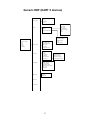
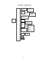
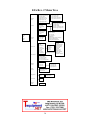
1
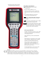
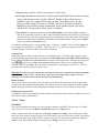
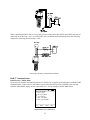
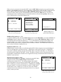
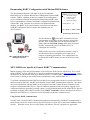
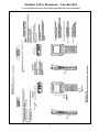
File No. 4100:440-6
EO 6112
September 2006
MFC 4100 HART® Communicator
USER’S MANUAL
MFC 4100 HART® Communicator OPERATOR USER’S MANUAL
IMPORTANT NOTICE
Important information on the product is contained in this
manual. Read this manual carefully and completely before
operating the product. For the safety of the operator and the
system, a thorough understanding of this manual is necessary
before commissioning, using or maintaining the product.
ASSISTANCE
For customer assistance please contact the local Meriam Representative or Meriam Process Technologies
directly. For a geographic listing of Representatives and contact information, visit our web site at
www.meriam.com and click on the “Representatives” link. Contact Meriam Process Technologies directly by
phone at (216) 281-1100 or by e-mail at [email protected]. Direct all assistance inquiries to Technical
Services.
HART® is a registered trademark of the HART Communication Foundation.
Meriam Process Technologies
10920 Madison Avenue
Cleveland, Ohio 44102
TELEPHONE: (216) 281-1100
FAX:
(216) 281-0228
E-mail: [email protected]
Web Site:
www.meriam.com
MFC 4100 HART Communicator
USER’S MANUAL
TABLE OF CONTENTS
Subject
Page
MFC 4100 Communicator Overview......................................................................................................... 1
Display Overview....................................................................................................................................... 1
Header Line Symbols ........................................................................................................................... 2
Keypad Overview....................................................................................................................................... 2
Alphanumeric / Symbol Entry............................................................................................................... 3
Left / Right Arrow Keys ....................................................................................................................... 4
Soft Keys............................................................................................................................................... 4
Thumb Operated Keys .......................................................................................................................... 5
General Operation ...................................................................................................................................... 5
Power Options....................................................................................................................................... 5
Navigating Menus on the MFC display ................................................................................................ 5
Turning on MFC ................................................................................................................................... 6
MFC Main Display ............................................................................................................................... 7
MFC Configurations Settings................................................................................................................ 7
1 Users............................................................................................................................................. 7
2 Applications ................................................................................................................................. 7
3 Lockouts....................................................................................................................................... 7
Lockout Code ............................................................................................................................. 8
Disable Lockout ......................................................................................................................... 8
Changing Lockout Code............................................................................................................. 8
4 Clock / Timers.............................................................................................................................. 8
Clock Edit................................................................................................................................... 8
Backlight (off timer)................................................................................................................... 9
Off Timer ................................................................................................................................... 9
5 Other (Model Info, Battery Type, HART Comm. Settings, PC Comm. Mode) ......................... 9
Battery Installation & Removal (all MFC models) .................................................................................. 10
External Connections to MFC.................................................................................................................. 10
AC Adapter ......................................................................................................................................... 10
HART jacks / lead set ......................................................................................................................... 10
DB-9 (Serial) Connection ................................................................................................................... 10
Hazardous Area Use................................................................................................................................. 11
Intrinsically Safe Operation ................................................................................................................ 11
HART® Communications with MFC 4100 ...............................................................................................12
HART Commands.................................................................................................................................12
HART Connections...............................................................................................................................12
HART Communications........................................................................................................................13
Initial Screens / Online Mode........................................................................................................13
Multidrop Poll (addresses 1 – 15) .................................................................................................14
Digital Poll (addresses 0 – 15) ......................................................................................................14
Manual Launch Device 0 Poll.......................................................................................................14
Offline Menu Mode.......................................................................................................................15
1 List / Show DOFs................................................................................................................15
2 List / Edit Configurations....................................................................................................15
3 Create Configurations .........................................................................................................16
4 Delete All Configurations ...................................................................................................16
Delete Individual Configurations / Clearing Configuration Memory ..........................................16
Online Setup Mode ......................................................................................................................16
Communications Trouble Shooting .............................................................................................17
More Status Message ...................................................................................................................17
Save / Send Configuration Functions...........................................................................................17
DOF Memory Maintenance ......................................................................................................................18
Documenting HART Configurations with Meriam DMS Software .........................................................19
MFC 4100 Device Specific & Generic HART Communication...............................................................19
Using Generic HART Communications ..............................................................................................19
DOF / Firmware Download Site ...............................................................................................................20
Who has access to the Download Site...................................................................................................20
PC Requirements for Download Operation ..........................................................................................20
Preparing the MFC................................................................................................................................20
Preparing to Download .........................................................................................................................20
Using the Download Site ......................................................................................................................21
Subscriber Options ................................................................................................................................21
DPC Manager Utility ................................................................................................................................21
Returning the MFC for Repair ..................................................................................................................22
APPENDIX
Product Specifications Overview..........................................................................................................23
MFC Models, Options, Ordering Information ......................................................................................24
MFC Accessories List ...........................................................................................................................24
Intrinsically Safe Control Document.....................................................................................................26
HART Command Structure Menu Trees ........................................................................................ 27-30
Generic (HART 5) ..........................................................................................................................27
1151 Rev 5 ......................................................................................................................................28
3051C Rev 2....................................................................................................................................29
EJA Rev 2 .......................................................................................................................................30
MFC 4100 HART COMMUNICATOR OVERVIEW
The MFC 4100 HART Communicator is a full function HART Communicator supporting Universal,
Common Practice and Device Specific commands for commissioning, configuration and maintenance
operations. HART field devices can be configured, polled, and trimmed using the MFC with HART
communications.
Lanyard
pins (2x)
Top View
AC Adaptor
jack
Display
Up / Select /
Down thumb
keys
Thumb
keys
Soft keys
Feature keys
Hand
strap
Alpha numeric
and edit keys
Battery
door
Side View
Front View
HART
connection
DB-9 Serial
connection
Bottom View
Note: For Intrinsically Safe MFC models, consult the Hazardous Area Use section of this manual for
specific details on use of approved MFCs and applicable restrictions.
DISPLAY OVERVIEW
The display of the MFC 4100 is a 128 x 128 pixel graphic display with backlight. Viewable area is 2.6” x
2.6” for 13 viewable message lines. The display provides three types of information: 1) header information
including display titles, HART communication status indicator, SHIFT indicator, alpha or numeric entry
mode indicator and battery gauge, 2) main data display section for display of MFC operating menus, HART
menus, and device information, and 3) footer information defining the display’s soft key functionality.
1
The following photo depicts the MFC
Configuration display and Soft keys:
HEADER LINE SYMBOLS
heart symbol indicates active HART
communication
u up arrow indicates SHIFT key is on
# number sign indicates numeric / symbol entry
is the present entry mode for all dual functions
keys
A letter indicates alpha entry is the present
entry mode for all dual function keys
battery symbol indicates MFC under battery
power; filled portion indicates remaining
battery
electrical plug symbol indicates the AC adapter
is connected and powering the MFC
BUSY
BUSY text box replaces either power symbol
when the microprocessor is busy executing a
previously requested task. Do not press keys
when this status symbol is displayed.
KEY PAD OVERVIEW
The MFC keypad has three basic key types: single
function keys, dual-function keys, and soft keys
with changing definitions.
Single function keys control a dedicated MFC
function.
Dual function keys, through the use of the Alpha
Lock or Shift keys, toggle between two separate
functions as needed to facilitate data entry.
Soft key functions change depending on the
operating mode. Soft key definitions are
displayed at the bottom of the LCD, just above
their respective gray soft keys.
The left hand thumb keys can be used to scroll
up, scroll down, and to select menu items.
On/Off
ON/OFF
Pressing the ON/OFF key powers up or turns off the MFC. As the unit powers up, an internal
diagnostic check is performed. Any abnormalities are posted on the display. The unit will briefly
display the MFC model number and then check for a HART device with address of zero. If a device
with zero address is found, the MFC immediately goes into online status and displays information
2
about the device. If no device is found, the MFC enters the MFC Main navigation screen. To turn the
MFC off, press and hold the ON/OFF key for approximately .5 seconds. Unit will power down
provided a critical HART operation is not in process.
QUICK
MENU
Home
QUICK
MENU
Quick Menu
The Quick Menu key initiates HART communications and then displays ten (10) HART menu
choices for the connected device. These menus are used to short cut the traditional HART menus to
enable the user to arrive quickly at desired functions. Typical Quick Menu options include: Main
Menu, Config Menu, Rerange, Basic Info, Construction Materials, Display, Sensors, Signal
Conditioning, Self Test. Quick Menu is disabled while critical HART operations are in process.
Home
The key sequence SHIFT, Home returns the user to the initial or “home” HART menu for the
connected device. The Home function is disabled while critical HART operations are in process.
Document
This key provides rapid access to HART communication Save/Send Configs options, List/Edit
Configs, and Create Configs functions for all MFC models. For Documenting operations this key also
provides documenting functions used with the Meriam Device Management System software. Access
to this key is disabled while critical HART communications are in process.
Display Contrast
This key allows the user to adjust the contrast of the LCD display for ambient lighting and user
preferences at any time and in any operating mode. Pressing and holding this key cycles through all
available contrast settings. After adjusting Display Contrast, wait at least five (5) seconds before
turning unit off to insure storage of new contrast setting. Ambient temperature compensation is
included in the MFC 4100.
Backlight
This key toggles the backlight feature between Off / Low intensity / High intensity to
illuminate the display for ambient light conditions. Battery life is impacted by use of the
backlight feature; High intensity is the most aggressive. An automatic shut-off timer is
available by pressing the Cfg soft key from the main menu.
2B
#
L
SHIFT
Alphanumeric / Symbol Entry
The alphanumeric keys have the heaviest population on the keyboard and are the method of entering
data into the MFC. Each MFC display has a default alpha or numeric / symbol entry mode based on
the most likely used mode for the display’s function. Pressing the ALPHA LOCK key activates the
other entry mode for alphanumeric keys. Pressing the SHIFT key converts the next key stroke to the
inactive entry mode and then automatically reverts back to the active mode. The letter “A” in the
display header line indicates the alpha input is active while a # sign in the display header indicates the
numeric / symbol input is active.
SHIFT
The SHIFT key is used to activate the secondary functions of the MFC’s dual function keys for the
next keystroke only. When the SHIFT key is active, an up arrow u is displayed at the top of the
display to the left of the battery power (or AC wall plug) symbol. SHIFT is also used to activate the
Page Up and Page Down soft key functions while viewing lists of information (installed DOFs,
stored configs, etc…).
3
ALPHA
LOCK
Alpha Lock
This key changes the keypads dual function keys from numeric/symbol entry mode to alpha
character entry mode and back. The active entry mode is indicated in the display header line next to
the power supply indicator on the upper right of the screen. The letter “A” in the display header line
indicates that alpha entry is active while a # sign in the display header indicates that numeric /
symbol entry is active.
Left / Right Arrow keys
These keys support cursor movement forward and backward for text / numeric editing needs. The
default edit mode is “overwrite.” For navigating functions, the left arrow emulates the Back soft key
and the right arrow emulates the Select soft key.
DEL
Delete
This editing key will delete the character located above the cursor in a text / numeric string.
INS
DEL
Insert
The Insert text edit function is activated by pressing the Shift, INS key sequence. Once activated,
the next alpha or numeric / symbol keystroke will be inserted into the open text field. The
“overwrite” default mode is restored upon completion of the insert operation.
Soft Keys (unlabeled)
The four gray keys located immediately below the display are Soft Keys. The specific functions of
these keys change depending on the operating mode of the MFC. Present definitions are displayed at
the bottom of the MFC display. Whenever possible the two Soft Keys on left are used for navigation
functions, the third from the left for action functions, and the right most for back function.
The following are examples of Soft Key definitions and their uses:
Up – moves indicator arrow up one line in a menu list
Down – moves indicator arrow down one line in a menu list
Select – selects the indicated menu item
Cfg – provides access to MFC configuration settings (Users, Applications, Lockouts, Clock /
Timers, Other)
Back – returns to prior display
Inc – Increment the value shown above the cursor
Dec – Decrement the value shown above the cursor
Next / Prev – these keys move to Next or Previous item within the list function accessed. Next
and Prev are for navigation only.
Done – Ends data entry session and proceeds with the selected operation
Edit – activate edit function for displayed parameter
Abort – aborts present operation without affecting prior settings or values
Save – saves the present value
Store – stores the present value
Yes – affirmative response to question presented
No – negative response to question presented
Trim – executes the trim function called for by the HART menu option selected
Chng – change the present menu setting
4
Thumb operated keys
Up, Select, and Down side keys provide convenient alternate methods of menu navigation. Use these in
addition to Soft keys and numbered HART menu lines to make menu navigation fast and easy.
= Up = Prev
= Select, Edit
Do not use these keys when the
BUSY
symbol is displayed.
= Down = Next
GENERAL OPERATION
Power options
The MFC 4100 can be powered for portable operation by two each 9-volt alkaline, Lithium or NiMH
batteries. Alkaline batteries are standard with the MFC shipment. Meriam offers NiMH batteries and
charger cradles (external charge only) as an option. For bench top operations and download operations, an
AC adapter (P/N A37003) is recommended.
Located in the upper right corner of the display, this icon displays the
remaining battery power. Fresh batteries produce a full black cell body. As the power
drains, the black segment retreats indicating remaining power.
When the MFC is used with the optional AC adapter (P/N 9B000007), the battery circuit is
bypassed and a wall plug icon replaces the battery icon on the display header. The AC adapter jack
is located on the left side of the MFC.
NOTE: Power icons may temporarily disappear during certain HART Communication operations
Navigating Menus on the MFC display
Several methods of navigating through the MFC menus are available to the user for maximum convenience
and utility.
1. Soft keys: Use Up and Down Soft Keys to move cursor arrow to the desired menu option. Then use
the Select soft key to accept the indicated choice. Soft key navigating tools are found throughout
the MFC Main displays and HART communication displays.
2. Side keys: Up, Down and Select keys are also provided on the left hand side of the MFC. These
keys are thumb operated and provide a convenient alternative to the Soft Key navigation buttons.
Side key functionality is not always available in the HART communication displays.
3. Multi-page lists: Multi-page lists have a
and/or symbol along the right hand side of the
display indicating the existence of information on the previous or next page(s). Several pages of
information may need to be viewed when reviewing lists of installed DOFs, stored configuration
files or finding a specific device in Offline Mode to create a configuration for. While in these list
areas, pressing the SHIFT key changes soft key definitions Select and Back to PgUp and PgDn,
respectively. To quickly advance to the next page of a list, press SHIFT and then the PgDn soft
key. To retreat to the prior page, press SHIFT and then PgUp. PgUp and PgDn soft keys remain
active until the Up or Down soft key is used or until SHIFT is pressed again.
5
4. Numbered HART menus: All HART displays have numbered menu lines when needed. This
gives fast access directly to the desired menu line. MFC displays also have numbered menus with
the exception of multi-page list screens.
5. HART menu HOME key: To quickly retreat from any location in the HART menu to the initial
HART menu screen for a device, press the SHIFT, HOME key sequence. This will return the
display to the initial HART screen. The Home function will be disallowed if a critical HART task is
in process.
6. Left / Right Arrow keys: Emulate Back and Select soft keys, respectively
Turning on the MFC
Use the dedicated ON/OFF key to power up the MFC. A brief diagnostic runs while the Meriam logo, MFC
model number, and MFC firmware version is displayed. A message is displayed indicating the MFC is
scanning for a HART device at address zero. The following scenarios are possible.
1. If the MFC is connected to a HART device with address = 0
(and there is sufficient loop resistance), the MFC immediately
establishes HART communication with the device. A display
similar to the example at right appears. The numbered menus
and Soft Keys are then used to commission, re-configure, or
maintain the connected device.
Online
3051 : PT-1012D
1 Device setup
2 Pres: 0.01 inH2O
3 AO: 4.001 mA
4 LRV: 0.00 inH2O
5 URV: 250.00 inH2O
Up
2.
If no HART device is connected, if a HART device with
address ≠ 0 is connected, or if a connected device is not found
due to wiring or loop resistance problem, the MFC will enter the
MFC Main navigation display depicted at right.
2.1 Select Online Setup once a HART device is connected
or once the wiring problem is resolved. A proper
connection will be indicated when line three changes
to “Device 0: *Online*”.
2.2 Select Online Setup if properly connected HART device
is setup for Multidrop loop or Burst Mode operation
(device address ≠ 0). The MFC will respond with a
statement and the Soft Key options shown at right. To
initiate a Multidrop poll, press the Multi soft key. To
retry the address 0 poll after rechecking connections,
press the Retry soft key. Press the Exit soft key enter
Offline mode.
Down
Communicator
1
2
Back
#
Online Setup
Offline Menu
Device 0: Not Found
Up
Down
Select
Communicator
Cfg
#
No device found:
Press Multi to begin
multidrop polling.
Retry to poll addr 0,
or Exit to go Offline.
Multi
6
Select
#
Retry
Exit
Communicator
MFC Main display
1
2
The MFC Main display provides access to Online Setup, Offline Menu
and to MFC configuration settings via the right hand Soft Key (Cfg).
#
Online Setup
Offline Menu
Device 0: *On-Line*
1. Online Setup is described above in Turning On the MFC.
2. Offline Menu is selected to provide access to Offline Utilities
such as List / Show DOFs, List / Edit Configurations, and
Create Configurations. The number of DOFs installed (HART
device profiles) and the number of device Configurations stored
are also available on Offline Utilities screen. See the Offline
section of this manual for more information.
Up
3. Cfg Soft Key is selected to configure MFC settings and view
MFC information such as Model, Serial, and Firmware
numbers, DOFs installed and Configurations stored.
Down
Select
Cfg
Configuration
Current Settings
1
Users
2
Applications
3
Lockouts
4
Clock/Timers
5
Other
#
Up
Back
Down
Chng
MFC Configurations Settings
1 Users
This menu item is only active for 21CFR Part 11 documenting versions. See separate 21CFR
Part 11 instructions in this case.
2 Applications
Various applications are available here including Digital Poll (polling device addresses 0 – 15) and
other user and factory applications.
3 Lockouts
The MFC HART Communicator can be programmed to lockout certain standard functions that a supervisor
may wish to control. The functions included are used to set up the MFC for normal use, change online
HART device configurations, create offline HART device configurations, update the installed DOFs list
(HART device profiles), or to update the MFC’s operating firmware. For example, locking out the Configs
feature turns the MFC into a read only HART communicator while locking out DOFs and Firmware prevents
unauthorized updates. The lockout can be limited to individual Lockout Details items or all Lockout Details
items can be locked out at one time.
To enable the lockout feature, press the “3” key or move the selection cursor
to the Lockouts menu
option on the Configuration screen (see below). Choose the Lockouts selection by pressing the Chng soft
key. The MFC will enter the Lockout Enable / Disable Screen. The current status is shown and three
choices are provided:
Configuration
Lockout : Disabled
1 Lockout Disable
2 PV Prompt Disable
3 View Details
#
Up
Back
Down
Chng
Configuration
Lockout Details
1 All
:
2 Setting
:
3 DOFs
:
4 Configs :
5 Firmware :
6 PV Prompt:
Up
Lockout Enable / Disable Screen
Down
#
Disabled
Enabled
Disabled
Disabled
Disabled
Enabled
Chng
Back
Lockout View Details Screen
7
1 Lockout: Indicates Enable / Disable status of Master Lockout feature.
2 PV Prompt: In addition to the primary variable, multivariable HART devices have secondary,
tertiary, and sometimes more variables. When PV Prompt on the Lockout screen is
“Disabled” and a Save command is issued by the MFC, the handheld saves only the
primary variable. When PV Prompt is “Enabled” and a Save command is issued, the
handheld saves the HART parameter information for all variables present. The factory
default for PV Prompt on the Lockout screen is “Disabled”.
3 View Details: This option takes the user to the Lockout Details screen listing all MFC parameters
that can be protected by lockout (see above right). Individual functions can be locked or, if preferred,
the lockout can be set to deny unauthorized access to all parameters. Press the number of the desired
menu item to toggle between Enabled and Disabled. Once satisfied with the setting, press the Back
soft key to return to the Lockouts screen.
To enable the lockout option, be sure the display reads “1 Lockout Enabled”. If not, press the Chng soft
key to toggle from “Disabled” to “Enabled”. Then press the “1” key, which corresponds to the Lockout
menu line number. The Lockout Enter Code screen is displayed.
Lockout Code
At this point the user will be prompted to enter a 3-digit lockout code. This code will be required to gain
access and change any parameter previously locked out. The number keys of the MFC will not work here.
Use the Increment, Decrement and Next Soft Keys to input a lockout code value. Alternatively you may use
the
green keys for Increment and Decrement functions. When you are satisfied with the
lockout code value, press Store. Note: the MFC is shipped with a factory lockout code of 3 2 1. The user
must enter this code the first time Lockout is used.
IMPORTANT: After the code is entered, the user must cycle the power to activate the lockout mechanism!
BE SURE TO SAVE THIS CODE IN A SAFE PLACE IN THE EVENT YOU FORGET THE NUMBER. ACCESS TO
LOCKED-OUT FEATURES WILL BE DENIED WITHOUT THE PROPER CODE.
Disable Lockout
When you wish to use a function or edit a value that is protected by the lockout code, enter the three digit
Lockout code when prompted and press Save. You will now be able to use the function or edit the setting as
normal. Entering an incorrect code will display the message “Incorrect Code” and allow you to try again.
Changing the Lockout Code
To change the lockout code, disable the lockout function for all the parameters selected, shut the unit off, and
follow the procedures outlined above.
4 Clock / Timers
Clock Edit
The Clock Edit option allows the user to correct the date and time of the MFC’s internal clock. To edit the
clock, press the “4” key or scroll Down to Clock Edit and press the Chng soft key.
Choose a clock or date option to adjust by scrolling Up or Down. Press Chng to choose that option. Enter
the correct value using the numeric keypad. You will be asked if you wish to save the new data. Press Yes to
accept the new value. Pressing No will take you back to the previous menu without making any changes to
the MFC clock. When all the changes are complete, press Chng to save the new value.
8
NOTE: When replacing the batteries, the date and time will remain active. Date & time information is
continuously powered by an internal, 10-year life back-up battery. This battery is not serviceable by the
user.
Backlight (off timer)
To conserve battery life, the MFC 4100 series allows the user to set the backlight to shut off after a certain
period of keypad inactivity. To change the backlight off timer on the unit, scroll Down to Backlight and
press Chng repeatedly until the desired value is displayed.
The shutoff timer can be disabled or set to shut off after time periods of from 1 minute up to 30 minutes.
NOTE: The Backlight Off Timer is disabled when the optional AC Adapter (P/N 9B000007) is powering the
MFC.
Off Timer
To conserve battery life, the MFC 4100 series allows the user to set the unit to shut off after a certain period
of keypad inactivity. To change the off timer on the unit, scroll Down to Off Timer and press Chng
repeatedly until the desired value is displayed.
The shutoff timer can be disabled or set to shut off after time periods of from 1 minute up to 2 hours.
NOTE: The Off Timer is disabled when the optional AC Adapter (P/N 9B000007) is powering the MFC.
5 Other
Model information and special settings are available from this menu item. Press number key “5”
or arrow to this menu line and press Chng to select. This reveals menu options for the following:
1 Model Info – select to view model number, serial number, firmware revision, last update
date, number of DOFs loaded and corresponding free memory space, and number of
HART configurations saved and corresponding free memory space.
2 Battery – shows present battery setting and optimizes the battery life indicator for the
battery type entered. Press number key “2” to scroll through Alkaline (factory default),
NiMH and Lithium battery options or arrow down to this menu item and press Chng
soft key repeatedly until the desired value is displayed.
3 HART – shows present HART® communication setting. The MFC is a HART® secondary
master. “Compatible” setting means the handheld will inform the user if another
secondary master is on line. Such situations will require the removal of the other
secondary master before HART communication can occur. “Fast” setting results in
faster communications but will cause interference if a HART® primary master is on
line (example: a HART® Multiplexer or I/O). In normal operation the MFC
automatically selects the best setting.
4 Enter PC Comm. Mode - When the MFC is connected to a PC for updates via DPC Manager (see
DPC Manager Utility section in this manual), a DB-9 serial cable is used. Occasionally a DB-9
Serial cable is encountered that does not have a DTR line. The DTR line is important to the
update process because it is used to initiate and confirm communication between the two
machines. If a DB-9 cable without a DTR line is used, the MFC must be manually placed in the
Enter PC Comm. Mode. Go to the MFC Main display and select Cfg. Select menu option 5
Other. Select the Enter PC Comm. Mode. Proceed with update and cycle MFC power when the
9
update is complete. It is recommended to use fresh batteries or an AC adaptor during update
procedures. This mode will automatically time-out after approx. 1 minute of inactivity and return
to the main display.
Battery Installation & Removal – all MFC models
The MFC monitors battery condition and displays a “REPLACE BATTERY” notice when the batteries get
low. The MFC will function for a short period of time after the notice is posted.
To install or remove the batteries, remove any soft case or protective boot and turn the MFC face down on a
work surface. Use a flat screwdriver to loosen the captive screw holding the battery door closed and remove
door. Replace batteries and make sure all connections are firmly secured. Replace door, tighten screw and
replace the soft case or boot.
Note: Replace both 9-volt batteries at once with all alkaline, all lithium or all NiMH cells. Do not mix
alkaline, lithium or NiMH batteries with each other or with other battery types. Battery replacement is
recommended when the “Replace Batteries” notice is posted on the display; however, the MFC will
function for a time after the notice is posted.
Note: For Intrinsically Safe MFC models, replace batteries only in Non-Hazardous Areas. Replace
batteries with approved types only. See the MFC Intrinsic Safety Control Document shipped with the
handheld for approved battery details.
External Connections to MFC
1. AC Adapter – The MFC 4100 can be powered by an external AC Adapter connected to the jack located
on the left side of the MFC. P/N 9B000007 bypasses the battery circuit to power the unit. The battery
symbol in the display header is replaced by a wall plug symbol.
WARNING: Serious injury or death may result from explosions. Do not make connection to the AC
adapter jack in a hazardous area. Use the AC adapter only in non-hazardous areas.
2. HART lead set – All MFC models are equipped with a standard size banana jack on 0.75” center. The
lead set supplied with the MFC has a standard banana plug on one end and mini-grabbers on the other for
convenient connections.
Note: For Intrinsically Safe MFC models, verify the instruments in the loop are installed in accordance
with intrinsically safe field wiring practices before making connection from the field device to the MFC’s
HART jack. See Hazardous Area Use Section of this manual for Intrinsically Safe guidelines /
restrictions.
3. DB-9 Connection Port – All MFC models are equipped with a standard DB-9 connection for RS-232
communications. The DB-9 provides the hardware interface to facilitate download / upload operations from a
host PC. This connection port facilitates download of MFC firmware improvements, HART® Device Object
Files (DOFs) and documenting operations. All MFC upgrades are available via the Meriam Download Site
accessible from www.meriam.com. The MFC will not need to be returned to Meriam for firmware updates
or for the addition of DOF files.
Note: Do not use the DB-9 connection port in Hazardous Areas. Use in non-hazardous areas only. See
Intrinsic Safety Control Document shipped with the handheld for more details on Intrinsically Safe MFC
units.
10
HAZARDOUS AREA USE
Intrinsically Safe Operation
The MFC 4100 HART Communicator is available with Intrinsically Safe Certification for use in Class I,
Division I, Groups A, B, C, and D, T5 hazardous areas. Refer to the Intrinsically Safe Control Document in
the Appendix of this User’s Manual for more details. The certification is to CAN /CSA-22.2 No.1010.1 &
157-92 and UL913 Fifth Edition Rev 2/21/97.
The following table identifies Intrinsically Safe MFC model numbers and areas of acceptable use.
Model Number
MFC 4100-11-1-01-0-01-1-01
Non-hazardous Area
√
Hazardous Area
√
MFCs with Intrinsically Safe certification can be identified by model number (see table above or the
Intrinsically Safe Control Document in the Appendix) or by a special label on the unit. A sample of the label
is shown below.
WARNING: Serious injury or death may result from explosions. Do not make connection to the DB – 9
connection port or to the AC adapter jack while in a hazardous area.
WARNING: Serious injury or death may result from explosions. Before making electrical connections to
an Intrinsically Safe MFC at the HART jacks, verify the instruments in the loop are installed in
accordance with intrinsically safe field wiring practices.
Note: Restrictions apply to the use of Intrinsically Safe MFC units in hazardous areas. Refer to the
Intrinsically Safe Control Document shipped with the handheld for exact details. The Appendix of this
manual contains an uncontrolled copy of this document. Meriam reserves the right to revise the Control
Document without notice. Contact Meriam (phone 800-356-9464) for the current Intrinsically Safe
Control Document.
For Intrinsically Safe MFC models, consult the Hazardous Area Use section of this manual for
restrictions, for special instructions in use, and for electrical connections.
11
HART® Communications with the MFC 4100
Overview
The MFC 4100 HART communicator provides device specific HART communication functions that
allow the user to poll, configure and maintain supported HART field devices. The MFC 4100 uses
Universal, Common Practice and Device Specific commands to facilitate communication with a HART
field device. Use the MFC to commission devices, for operational re-configuration needs, or maintain
devices through analog and sensor trim adjustments and many other features.
The MFC 4100 will communicate with any HART device through Universal and Common Practice
Commands using the standard Generic DOF (Device Object File) but must have the DOF for a specific
HART device installed before it can execute Device Specific Commands. Consult the large and growing list
of available DOFs at www.meriam.com for an up to date list of HART devices with device specific support.
The list is found under the Resources tab, Download Center page, by selecting the “Available DOFs” link.
When HART device support for new devices becomes available, the MFC can be easily field updated via
Internet downloads.
HART Commands
Three HART command types are used by the MFC 4100 to communicate with HART field devices. First,
Universal Commands are primarily used to identify a field device by its model number and tag number and
to read process data from the device. This communication is referred to as “polling”. The MFC 4100 can poll
any Hart Device. Second, Common Practice Commands are used for calibration and maintenance functions
that are common to many devices. An example of this would be trims or adjustments for the devices’ analog
outputs. Third, Device Specific Commands are used to handle functions that are unique to a particular device
or manufacturer. Examples of these commands include sensor zero, sensor trim, calibration curve
characterization, density inputs required for calculations made by the HART device or other configuration
functions unique to the specific device.
HART Connections
HART connections are made using two standard banana jacks (3/4” center) located at the top end of the
MFC 4100. Refer to the following diagram. Polarity is not a concern for HART connections so both jack
collars are black. Meriam supplies a HART lead kit (P/N A900529-00014) complete with mini-grabber
connections and a 250 Ω load resistor with each model MFC 4100.
MFC 4100 with HART®
HART® connections are standard banana jacks (3/4” center)
For low load loops (less than 250 Ω), a 250 Ω resistor will need to be added to the loop to insure reliable
HART communications. Meriam supplies a 250 Ω load resistor in the form of a standard adaptor (P/N
A36821). Refer to the following diagram for connection details.
12
When connecting the MFC 4100 to a loop with a resistive load greater than 250 Ωs, the HART jacks may be
connected across the loop + and – or to the HART device communication terminals. Refer to the following
diagram for connecting across the loop + and -.
Connecting to the MFC communication terminals
HART® Communications
Initial Screens / Online Mode
Upon power up the MFC automatically detects if a field device is connected and attempts to establish HART
communications. When a device with address zero is found, the MFC provides feedback to the user and
starts the initial HART display for the connected device. See an example of Online Mode below.
Online
3051 : PT-1012D
1 Device setup
2 Pres: 0.01 inH2O
3 AO: 4.001 mA
4 LRV: 0.00 inH2O
5 URV: 250.00 inH2O
Up
Down
Select
#
Back
Initial HART Screen / Online Mode
13
When no device connection is detected the MFC enters the MFC Main navigation screen and the message
Device 0: Not Found is displayed. Upon selecting the “1 Online Setup” option, the MFC checks again for
Device address 0 and if not found displays the MFC Multidrop / Retry 0 screen. This screen allows
selection of either of three options: launch Multidrop poll by selecting the Multi soft key, retry Device 0
communication after re-checking physical connections to the device by the selecting Retry soft key, or to
Exit to Offline mode by selecting the Exit soft key.
Communicator
1
2
#
Online Setup
Offline Menu
Communicator
#
No device found:
Press Multi to begin
multidrop polling.
Retry to poll addr 0,
or Exit to go Offline.
Device 0: Not Found
Communicator
Multidrop Polling…
#
Scanning Address # 3
Up
Down
Select
Cfg
Multi
Retry
Exit
Stop
Abort
MFC Main Navigation Screen
MFC Multidrop / Retry 0 Screen
Multdrop Polling Screen
No device or Non-zero address found
No device or Non-zero address found
Multidrop & Burst Mode Support
Multidrop Poll (addresses 1 – 15)
To initiate a Multidrop Poll, select the Online Setup option from the MFC Main screen when the Device 0:
Not Found message is displayed. Then select Multi soft key from the MFC Multidrop / Retry 0 screen.
This function polls for all non-zero addresses (1 – 15). Located addresses are listed on the display as the
remaining addresses are checked. When polling is complete, or upon pressing Stop after the address of
interest is found, use the soft key controls to select the address of interest. The initial HART menu for the
device selected will then be displayed for use.
Digital Poll (addresses 0 – 15)
Digital Polling is a special feature accessible through the MFC’s Main navigation screen and the Cfg soft
key. Press the Cfg soft key and then select the “2 Applications” menu option. Select the “1 Digital Poll”
menu option to launch a polling operation that includes address 0 and ends with address 15. All addresses
on the loop will be displayed on the MFC’s screen. The address of interest can be selected from the list to
launch HART communication with that device. Digital Poll can only be launched from this location in the
handheld’s menu structure.
Manual Launch of Device 0 Poll
When the message Device 0: *On-line* is displayed on the MFC Main
navigation screen, selecting Online Setup will launch HART
communication with the device. The message indicates that a HART
device with address 0 has been detected at the HART connection and the
MFC is standing by to initiate communications. The Device 0: *On-line*
message is shown 1) if a physical connection is made to a HART device
after the MFC power is turned on or 2) if the user exits from a HART
communication session without disconnecting the lead wire by using the
soft key controls provided.
Communicator
1
2
#
Online Setup
Offline Menu
Device 0: *On-Line*
Up
Down
Select
Cfg
MFC Main Navigation Screen
Manually launch polling on device 0.
14
Offline Menu Mode
The Offline Menu gives the user access to lists and functions that can be
viewed or performed in Offline Mode at the user’s convenience for the
purposes of reviewing the MFC’s DOF list, reviewing stored device
configurations or creating HART configurations. Stored configurations can
also be edited and then applied later to a connected HART device. When the
Offline Menu is selected from the MFC Main navigation screen, the
display at right is shown.
Offline
#
Utilities
1
List/Show DOFs
2
List/Edit Configs
3
Create Configs
4
Delete All Configs
DOFs: 315
Configs:
3
Up
Down
Free: 42%
Free: 99%
Select
Back
HART Offline Menu Screen
1 List / Show DOFs:
Provides a list of installed DOFs (Device Object Files) used by the MFC to communicate with HART
devices. Lists can be viewed by Manufacturer, by Device Name or by stepping through all Devices one at a
time. Use the soft key controls to move through the list. Pressing the SHIFT key changes soft key
definitions Down and Up to PgUp and PgDn. To quickly advance to the next page of a list, press the PgDn
soft key. To retreat to the prior page, press the PgUp soft key. Once engaged the PgUp and PgDn soft keys
remain active until the Up or Down soft keys or SHIFT is pressed again.
2 List / Edit Configs:
This screen lists all stored HART configurations by Tag Number. The
configurations stored enable fast commissioning of replacement devices,
cloning of existing systems, or re-configuring for changes in process
conditions or batch runs. Any configuration in the list can be sent to
another HART device of the same manufacture and model. The display
can show 20 character tag numbers. Truncated tags are listed if more than
20 characters are used. Moving the cursor down to the tag of interest and
pressing the Select soft key will provide a detailed information screen,
including full tag number up to 28 characters, for the tag of interest (see
example below, right).
The editing function allows review of all HART parameters in a configuration and modification of editable parameters. The edit function can be
locked out if desired (see the Lockout section of this manual for more
information). To view detailed information of a stored configuration, move
the cursor to the desired tag number and press the Select soft key. The
Config Detail screen (see example at right) provides information to help
the user confirm the identity, origin, and save date/time of the configuration.
Pressing Select again opens the configuration for review or offline editing.
New configurations saved are added to the bottom of the List / Edit Config
list. If multiple entries for one device are shown, the most recently saved
configuration is always shown at the bottom.
Offline
List/Edit Configs
PT-105A
PT-105B
DPT-201C
TT-312A
TT-312A
FE-201
FE-201
PT-6174
Up
Down
#
Select
Back
Offline List / Edit
Configs Screen
Offline
List/Edit Configs
Tag: PT-105A
#
Device ID 1365
PV: Pressure
Endress + Hauser
Cerabar S
Complete Config
Uses DOF 11070702
51 Variables
12/18/03 4:58 PM
Copy
Del
Select
Back
Offline List / Edit
Entries in the List / Edit Config list may have been saved or created from
Configs Detail Screen
various sources. Possible sources include the save command from a
connected HART device, created in the MFC using the Create Configs
function, copied from another configuration and renamed, or created by editing an existing file. The MFC
will also list configurations downloaded from the separately available Device Management System software
from Meriam (see www.meriam.com/dm_solns.htm for more information). Tag numbers, date / time of
save, type of configuration stored, and other information are displayed under List/Edit Configs.
Configuration types are:
15
Complete Config
= saved from connected device in Online mode, or a
complete config that was downloaded from DMS
Default Config
= created by MFC in Offline mode, or created in DMS
and downloaded to MFC
Edit Vars Only
= created by editing an existing configuration and includes only the edited parameters
MVar Primary Cfg = for multivariable devices – Primary Variable configuration
MVar Sub Config = for multivariable devices – Sub-configuration (secondary, tertiary, fourth, etc
variables)
3 Create Configs:
The Create Configs function allows the user to configure a HART device file in Offline Mode for sending
to the intended device later when connected in the Online Mode. Use the soft key controls to move through
the list and select the device model number required. The menus prompt the user to make the necessary
configuration selections, tag the file for later retrieval and use, and edit configuration lines as required. This
function can be locked out. See the Lockout Section of this manual for more information.
4 Delete All Configs:
The Delete All Configs function clears all configurations from memory (including active and hidden
configs). When this menu option is selected, the MFC will ask “Delete ALL Configs… ARE YOU
SURE???” Select Yes to clear all stored configurations from memory.
Delete Individual Configs / Clearing Configuration Memory:
Individual stored Configurations may be deleted with MFC Del soft key
function (see example at right). When this menu option is selected, the MFC
will ask “Delete CURRENT Config… ARE YOU SURE???” Select Yes to
clear only the selected configuration from memory.
The Del key only hides the record from the MFC screen; it does not clear
memory space. This function can be locked out. See the Lockout Section of
this manual for more information.
Offline
List/Edit Configs
Tag: PT-105A
#
Device ID 1365
PV: Pressure
Endress + Hauser
Cerabar S
Complete Config
Uses DOF 11070702
51 Variables
12/18/03 4:58 PM
Copy
Del
Select
Back
Offline List / Edit
Configs Detail Screen
Online Setup Mode
Online Setup is the normal HART communication mode for the MFC. This
mode enables communication with HART field devices at the Universal,
Common Practice and Device Specific Command levels for full device setup
and functionality.
Menus displayed for the connected device follow the HART device
manufacturer’s menu structure for the connected device. Consult the device
manual for menu structure details.
MFC features two unique online features for added convenience to the
user.
Device Setup
3051 :PT-1012D
1 Process variables
2 Diag/Service
3 Basic setup
4 Detailed setup
5 Save/Send
6 Review/Edit
Up
Down
Select
#
Back
Online Device Setup Screen
1. Live HART connection monitor: MFC display lets you
know from the Main navigation screen when a device is
* On-line * and ready for communication.
2. Review/Edit: this menu option allows the user to review
configurations line-by-line. MFC supports editing of the
configuration once the parameter of interest is located.
16
Communications Trouble Shooting
If an operating HART device is connected to the MFC but the “Device 0: Not Found” notification is
received, a Multidrop Poll may be executed to determine if the connected device has a non-zero address.
Select Online Setup from the MFC Main navigation screen and then select the Multi soft key to initiate the
Multidrop poll. If the “No Devices Found” message is received, then the loop connections to the MFC
should be carefully checked.
If an operating HART device with address zero (0) is connected to the MFC but the “Device 0: Not Found”
notification is received, the loop connections to the MFC should be carefully checked.
Make sure all connections are correct and secure. Check for shorts, open circuits and multiple grounds.
Determine if the loop resistance is greater than 250Ω and less than 1100Ωs. If less than 250 Ω then use the
supplied 250 Ω load resistor in series with the loop (see diagram HART Connections section).
If communication is still not established, check the List / Show DOFs menu under Offline Menu. Check
the list for the presence of the “Generic” DOF under the manufacturer name “Meriam.” If “Generic” is
found, then HART communication is possible when the device is properly wired and connected to the MFC
(see connection troubleshooting details above).
When the message “Generic” is displayed after connecting to a HART device there are two possible causes:
1) No device specific DOF for that device is currently installed in MFC memory. Check for
availability of the DOF needed by going to the Available DOFs site at
www.meriam.com/customers/past.asp . Sort the list by clicking on any column header. For
download instructions, see the DOF / Firmware Download Site section of this manual.
2) The connected HART device supports only HART Universal and Common Practice commands (i.e.
generic commands). There are several such devices on the market, particularly level type devices.
More Status Message
HART device events (diagnostic flags) cause the MFC to display a “More Status Message” at the bottom
of the display. This message is a notice to the user that one or more diagnostic warnings are available in
the Review Status menu option of the connected device. Upon receipt of this message, enter the HART
mode and select Detailed Setup / Diagnostics – Service / Test – Status / View Status to retrieve the
diagnostic information.
Save / Send Configuration Functions
HART device configurations may be saved to MFC memory or sent from MFC memory to a HART
device. These functions are useful for cloning a device configuration for use in another transmitter of the
same configuration, for recording as-found and as-left configurations for later review, for returning
HART devices to previously used configurations, etc…
The Save / Send function may be accessed in one of two ways:
1. Press the Document key
on the MFC for the screen shown
at right. Then select the Save/Send Configs” menu option to
launch a HART communication poll and use the Save / Send
options.
2. Use the Save / Send menu option within the HART device’s
standard menu. The MFC would be in Online mode in this
case. Save / Send is normally found under the “Device Setup”
menu option on the initial HART display for the device.
17
Document
#
Utilities
1
Save/Send Configs
2
List/Edit Configs
3
Create Configs
4
Delete All Configs
Configs Stored:
Up
Down
98
Select
Back
Document Key Menu Screen
DOF Memory Maintenance
DOF flash memory will become fragmented after many DOF download sessions to add new or
update existing DOFs. Fragmentation reduces the total number of DOFs that can be saved in
memory. 600 DOFs is the nominal capacity of the flash memory). When fragmentation becomes
extreme, the MFC will not accept additional DOF downloads. Periodic DOF memory
maintenance will be needed to optimize DOF memory.
The Offline screen indicates the number of DOF files stored in
memory and the percentage of free memory available for
additional files. 320 DOFs ideally use about 58% of the available
memory, so 42% of DOF memory should be free. The example at
right indicates that only 27% of DOF memory is free. This
indicates fragmentation.
To optimize DOF flash memory, it is necessary to delete all DOFs
and then reload them all in one session. Connect the MFC to a host
PC that has DPC Manager installed (see the DPC Manager Utility
section of this manual for more information). Launch DPC
Manager and select the “Manage DPC Device Driver and
Firmware Updates” option. Go to the Tool Bar and click on
“Settings”, then click on the “Advanced” option. The following
screen will appear.
Offline
#
Utilities
5
List/Show DOFs
6
List/Edit Configs
7
Create Configs
8
Delete All Configs
DOFs: 320
Configs:
3
Up
Down
Free: 25%
Free: 99%
Select
Back
HART Offline Menu Screen
Under “Update DOFs on DPC” section on
left side, click on the “Auto” button. An
Auto Install dialog box will appear.
Select the “Yes” response to the “DOF
Update Options? question to erase all
existing DOFs and re-load DOFs from
the default DOF directory.
320 DOFs will take approximately 90
minutes to load.
18
Documenting HART Configurations with Meriam DMS Software
The documentation functions of the MFC 4100 provide additional
functionality for use with the Meriam Device Management System (DMS)
software. DMS is a database product for complete device management
services including calibration documentation with the Meriam MFT 4000
Series of multifunction calibrators and HART configuration documentation
with the MFC 4100. Complete device histories are maintained in the
database. For HART devices these histories can include as-found and asleft HART configuration data to complete this important part of a
device’s history.
Document
#
Utilities
1
Save/Send Configs
2
List/Edit Configs
3
Create Configs
4
Delete All Configs
Configs Stored:
Up
Down
98
Select
Back
Document Key Menu Screen
The Document key
on the MFC 4100 models will save
configurations in as-found or as-left categories as selected by
the user. These configuration files can be uploaded later to
DMS. When the Save/Send Configs menu option is selected
the MFC automatically polls for an Online device for
subsequent user selections.
MFC 4100 with Meriam Device
Management System
DMS can also be used as a configuration repository ready to
download stored device configurations for batch runs or
changes in operating requirements. New configurations can
be downloaded to MFC memory for later recall and use in the
field.
MFC 4100 Device Specific & Generic HART® Communications
Meriam supports a large and growing number of Device Specific DOFs (Device Object Files). For a current
listing of HART® devices with full Device Specific communication support, go to www.meriam.com , select
the Resources tab, Download Center page, and then select the “Available DOFs” link. Information found there
can be sorted by clicking on the column headers (manufacturer name, model number, etc…).
To facilitate communication with HART devices that are not yet supported with Device Specific DOF files or
that do not require DOF files, the MFC 4100 includes Generic HART Communication capability. This allows
the user to communicate with any HART device using Universal and Common Practice commands to poll,
configure, and maintain HART devices. Specific functions supported include most polling, tagging, device
configuration and trim operations for analog outputs. Generic communications do not support Device Specific
commands for higher order HART functions (see the HART® Commands section of this manual or the User’s
Manual for the HART device of interest for more information on the three command levels).
Using Generic HART Communication
The MFC 4100’s Generic HART Communication mode starts automatically when HART communication is
initiated with a device for which no Device Specific DOF (device object file) is stored in the handhelds flash
memory. When this occurs, line two of the display will indicate “Generic” and the device tag number.
19
In general, the Generic HART mode operates similarly to its device specific DOF counterpart (see HART
Communication section of this manual for more details). However, the MFC does not display Device Specific
related communication menus or options when in the Generic communication mode. For example, the Zero and
Sensor trim menu options (normally executed by Device Specific commands) are not displayed for pressure
transmitters without DOF support. Please see the Download Site section of this manual for information on
downloading the latest Device Specific DOF files to your MFC.
DOF / Firmware Download Site
Overview
Firmware upgrades and new DOFs can be downloaded via the Internet from the DOF Download Site. MFC
units already in service in the field do not need to be returned to the factory for firmware upgrades released
by Meriam. The user can simply download the files to a PC having Internet access and upgrade the MFC
firmware using the DPC Manager utility. DOF’s are also available on this site. The Download Site enables
users to stay current as Meriam releases new DOF’s or revisions of existing ones. Automatic email notices
of new DOF postings are sent to all users who log on to the Download Site and register their email address.
Who has access to the Download Site?
All MFC customers can purchase a subscription to the DOF Download Site. These customers may download
any published file from the site to their host PC upon entry of the proper authenticating codes (shipped with
unit). Contact Meriam at 216-281-1100 or [email protected] for more information and to purchase
subscriptions.
PC Requirements for Download Operations
Meriam recommends IBM compatible Pentium I PCs or higher for download operations. The PC should
have an available RS-232 port, minimum modem speed of 28K and access to Internet service. USB ports can
be used with USB to serial adapters as well.
Preparing the MFC
All MFC models come ready to connect to an IBM compatible PC using a standard DB-9 socket located at
the bottom of the MFC enclosure. A six-foot male DB-9 to female DB-9 cable (P/N A90047-00052) is
shipped with each handheld. Similar cables are acceptable. Connect the MFC to the PC and power up the
MFC using fresh internal batteries or the optional AC Adapter (P/N A37003). The MFC is ready for
download operations.
Preparing to Download
Establish connection to the Download Site by going to the Meriam website at www.meriam.com. Click on
the “Download Site” link on the home page navigation bar to access all download functions. A list of
currently available DOF’s for HART device communication can be viewed at the www.meriam.com
website. Click the “Available DOFs” link on the home page navigation bar to view an up to date list of
available DOF’s.
20
Using the Download Site
The log in page of the Download Site requires the user to enter a valid User Name and Password to
authenticate user identity and permit entry to the Site. These two codes are initially assigned by Meriam and
can be found on a card included with shipment. Locate the card and place in a safe place for future
reference.
Once a user is logged on to the Site, the Latest Release Notes screen appears listing and describing the most
recent firmware releases posted and the posting date. Individual files can be downloaded from the detailed
description page of each DOF or firmware file listed. Also available on this screen are the navigation
buttons for Current Release Notes, File Download Area, and Subscriber Options.
The Current Release Notes screen describes all DOF and firmware releases available and dates posted.
Five (5) columns are shown on this page: Date, Title, Description, Manufacturer, Model. These categories
will assist the user in finding the release descriptions of the DOF, DPC Manager or MFC Firmware releases
of interest. Each column can be sorted to assist searches of the release database. Individual files can be
downloaded from the detailed description page of each DOF or firmware file listed. Also available on this
screen are the navigation buttons for Latest Release Notes, File Download Area, and Subscriber Options.
The File Download Area screen is the actual download page. Select from a list of downloadable firmware
files (including DPC Manager Utility, MFC Firmware, and DOF’s) by locating the file name of interest with
the PC mouse and left clicking. Dialog boxes guide the user through the process. All files can be
downloaded at one time if desired. Dialog boxes again guide the user through the process. Also available
on this screen are the navigation buttons for Latest Release Notes, Current Release Notes, and Subscriber
Options.
Subscriber Options
The Subscriber Options screen provides useful account information and is displayed immediately upon first
log in. User Name and Password for the account are listed, as well as the subscription expiration date. In
addition, this screen allows the user to customize the account Password. The user should provide contact
information and e-mail address that allows Meriam to provide notification of new firmware updates, DOF
releases, and subscription period expiration. Press the “Update Subscriber Options” button to save all
Subscriber Options changes.
To report any difficulties with downloading operations, please contact Meriam at 216-281-1100 or
[email protected]
DPC Manager Utility
DPC Manager Utility should be installed onto the host PC from the User’s Manual CD (included with MFC
shipment) or from the Meriam Download Site where it can be found at the bottom of the File Download
Area page. DPC Manager coordinates the download operations from the host PC to the MFC. Periodic
improvements may be incorporated into this Utility. Therefore, Meriam recommends periodic comparison of
the DPC Manager version installed on the host PC to the latest available version on the Download Site to
insure use of the most up to date Utility tool. Directions for using DPC Manager are found under the Help
Tool Bar selection.
21
RETURNING THE MFC FOR REPAIR
In the event that a MFC requires service and must be returned for repair, please contact Meriam at the
numbers listed below.
DO NOT send any unit in for repair without first contacting Meriam for a Return Material
Authorization (RMA) number. If this number has not been obtained and clearly marked on the
package being shipped back, the unit will be returned at the shipper’s expense. This number will be
provided by the Meriam Repair Department when you call, fax or e-mail your information. An RMA number
must accompany all incoming packages to insure proper tracking, processing and repair work.
To assist us in processing your repair request, please have the Model & Serial Number of the unit available
when you call. This information is located on the MFC label. This information can also be obtained directly
from the MFC display by pressing the Cfg soft key from the MFC Main display, then “5 Other” and then
“1 Model Info”. See the MFC Main display section in this manual for more details.
Meriam Process Technologies
10920 Madison Avenue
Cleveland, Ohio 44102
TELEPHONE: (216) 281-1100
FAX:
(216) 281-0228
E-mail: [email protected]
Web Site:
www.meriam.com
22
APPENDIX
PRODUCT SPECIFICATIONS OVERVIEW
BASE UNIT: 10" L x 4.25" W x 1.65"D ABS plastic case with optional shock absorbing boot, 19ozs. including
batteries
DISPLAY: 128 x 128 pixel graphic display, 2.6” x 2.6” viewable area, backlight
POWER: two (2) 9-volt alkaline batteries, two (2) 9-volt Lithium batteries, two (2) 9-volt NiMH batteries or optional
100 – 240 Vac power adapter (P/N A36742)
TEMPERATURE SPECIFICATIONS:
Storage:
-40° F to 140° F (-40° C to 60° C)
Operating: 23° F to 122° F (-5° C to 50° C)
CONNECTIONS: HART: Standard banana jacks (¾” center)
PC Data transfer: DB-9 serial connector
Power: AC Adapter jack
AUTO SHUT-OFF - occurs after user-selected period of keypad inactivity or can be disabled, both MFC and backlight
DIAGNOSTICS – MFC 4100 self-tests upon power up. Advisories are posted on the display.
APPROVALS: Class I, Div I, Groups A, B, C, D, T5 certified by MET Laboratories, Inc per UL3111-1, CAN/CSA22.2 No. 1010.1 & 157-92 and UL913, Fifth Edition, Rev. 2/21/97
CONTRAST – direct adjustment of display contrast in any mode; automatic compensation for ambient temperature
changes
SECURITY LOCKOUT – MFC 4100 Settings can be locked out entirely or by specific feature.
CE compliance
MEMORY – separate, dedicated, non-volatile flash memory for MFC firmware, DOFs, and Configurations
DOF Memory: 600 HART devices (based on average DOF size)
Configuration Memory: 200 HART devices (based on average configuration size)
23
MFC MODELS, OPTIONS, ORDERING INFORMATION
MFC MODEL NUMBER
®
4100 HART Communicator (Includes CE Mark, HART leads Kit, Batteries, RS-232 Serial Cable, User's Manual,
Universal Power Adapter, Protective Boot) (Note: Standard items may be different based on OEM code)
Code OEM Field (or Reserved for outside price sheets)
-11
"MFC" prefix: example: MFC4100
Code Documenting Options
-1
Standard Documenting (Interface to DMS Software for HART Configuration Data)
-2
21CFR Part 11 Enabled Version of Documenting Option Above
Code Certification Options
-00 CE Mark (Standard on all units)
4100
-11
-1
-01
-2
-01
-0
-01
Full Model ID: MFC4100-11-1-01-2-01-0-01
Meriam
Standard Documenting
Intrinsic Safety
Fitted U.I.P Soft case
English User's Manual
Std. 3 Year DLS
English Firmware
IS - Intrinsic Safety Certification by MET Laboratories per CSA C22.2 No. 1010.1-92, C22.2
No. 157, and UL913, Fifth Edition Rev. 2/21/97 for Class I, Div I, Groups A, B, C & D
Code Carrying Case and Strap Options
-0 Rear Hand Strap and Slip-On Protective Boot (Standard on all units)
-1 Adjustable Hanging Strap
-2 Soft Carrying Case
-3 Adjustable Hanging Strap, Soft Carrying Case
Code User's Manual Language options
-01 English language
Code Download Subscription (DLS) Fee options
-0 No DLS
-1 Standard 3-year DOF Download Subscription
-2 Discounted DLS Price Based on Volume Discount
Code Firmware Language Option
-01 English language
Calibrator/
Hart Communicator
-01
Note: Only MFC4100-11-1-01 portion of the model number
will be tracked by DPC Manger and DMS Software
MFC ACCESSORIES LIST
A36885
Protective red boot provides degree of protection against drop related damage; slip on
A900529-00014 HART Test Lead Kit (inc'd w/ MFC) - std banana plugs, mini-grabbers, 250 Ω
resistor
A36821
Std size 250 Ω shunt resistor (inc'd w/ MFC) - req'd for HART low resistance loops
A900447-00052 DB-9 cable, Male x Female, 6 ft length (incl’d w/MFC);
Required for updates / communication
A36875
MFC carrying case (inc'd w/ MFC) - custom soft case with adjustable shoulder strap
and HART lead compartment
A36937
Adjustable, detachable hanging strap (inc'd w/ MFC) clips directly to MFC attach
points
A900614-00006 9 Volt Alkaline Battery (inc'd w/ MFC) (2 req'd)
A900614-00009 9 Volt Lithium Battery (2 req'd), approx 3x life of alkaline batteries, best for cold
service
A900614-00015 9 Volt NiMH Batteries (2 req'd)
24
MFC ACCESSORIES LIST, con’t
A37134
NiMH battery charger, 100 – 240 vac, 50/60 Hz, universal plug kit
9B000007
Power adapter, 100 Vac to 240 Vac, 50-60 Hz universal plug kit (incl’d w/VA-02 MFC)
F/N MFC 4100:440 Paper instructions for MFC 4100 (PDF instructions sent with each MFC on CD)
25
Intrinsic Safety Document – Uncontrolled
For Controlled document see drawing shipped with actual handheld
26
Generic DOF (HART 5 devices)
“Config Menu”
Process Vars
Sensors
“Main Menu”
Device Config
PV
AO
LRV
URV
%Range
Analog Trim
Basic Info
Hart Output
Diagnostics
“Process Vars Menu”
PV
% Range
AO
“Sensor Menu”
Rerange
Signal Conditioning
“Analog Trim Menu”
4mA Analog Trim
20mA Analog Trim
DAC Trim
Loop Test
Scaled DAC Trim
“Basic Info”
Tag
Date
Descriptor
Message
Private Label
Revisions
“HART Output”
Polling Address
Burst Mode Select
Burst Command Number
Device ID
Preambles
Diagnostic Menu”
Self Test
Loop Test
Save Send
Review Edit
27
“Rerange Menu”
LRV (edit)
URV (edit)
Set 4mA Range
Set 20mA Range
LSL
USL
“Signal Conditioning”
Transfer Function
Damping Value
Units
Analog Alarm
“Revisions”
HART Revision
Device Revision
Software Revision
Final Assbly Number
1151 Rev. 5 Menu Tree
Process Vars
Sensors
Pressure Value
Pressure Percent Range
Analog Output
Zero Trim
Lower Sensor Trim
Upper Sensor Trim
Lower Sensor Trim Point
Upper Sensor Trim Point
Pressure Trim
Re Range
Signal Cond
Pressure Lower Range Value
Pressure Upper Range Value
Set 4mA Range
Set 20mA Range
Pressure Lower Range Limit
Pressure Upper Range Limit
Pressure Output Transfer Function
Pressure Damping Value
Pressure Units
Analog Output Alarm Select
Device Setup
PV
AO
URV
LRV
% of Range
Analog Trim
Basic Info
Hart Output
Trim 4mA
Trim 20mA
Loop Test
Tag
Date
Descriptor
Message
Private Label
Revisions
Const Mats
HART Revision
Device Revision
Software Revision
Final Assembly Number
Module Isolator Material
Module Fill Fluid
Gasket Material
Flange Material
Drain Vent Material
Flange Type
Remote Seal Isolator
Material
Flange Size
Number of Remote Seals
Remote Seal Fill Fluid
Remote Seal Type
Polling Address
Burst Mode Select
Burst Com Number
Device ID
Preambles
Diagnostics
Self Test
Loop Test
Save / Send
Save
Send
Review / Edit
Variables
28
Perform Test
Test Results
3051C Rev. 2 Menu Tree
Process Vars
Pressure Value
Pressure Percent Range
Analog Output
Temperature Value
Sensors
Sensor Trim
Re Range
Signal Cond
Units
Zero Trim
Lower Sensor Trim
Upper Sensor Trim
Lower Sensor Trim Point
Upper Sensor Trim Point
Pressure Lower Range Value
Pressure Upper Range Value
Set 4mA Range
Set 20mA Range
Pressure Lower Range Limit
Pressure Upper Range Limit
Pressure Units
Temperature Units
Device Setup
Press
AO
URV
LRV
Pressure Units
Pressure Output Transfer Function
Pressure Damping Value
Analog Output Alarm Select
Analog Trim
Basic Info
Hart Output
Trim 4mA
Trim 20mA
Loop Test
Tag
Date
Descriptor
Message
Revisions
Const Mats
Universal Revision
Transmitter Revision
Software Revision
Final Assbly Number
Device ID
Polling Address
Request Preambles
Burst Mode Select
Burst Command Number
Diagnostics
Self Test
Loop Test
Save Send
Save
Send
Review Edit
Variables
Self Test
Status Display
29
Module Isolator Material
Module Fill Fluid
Gasket Material
Flange Material
Drain Vent Material
Flange Type
Remote Seal Isolator
Material
Flange Size
Number of Remote Seals
Remote Seal Fill Fluid
Remote Seal Type
EJA Rev. 2 Menu Tree
Process
Vars
Sensors
Pressure Value
Pressure Percent Range
Analog Output
Temperature Value
Static Pressure Value
Engr Display Unit
Engr Display Value
Pressure Lower Range Value
Pressure Upper Range Value
Set 4mA Range
Set 20mA Range
Pressure Lower Range Limit
Pressure Upper Range Limit
Sensor Trim
Re Range
Signal Cond
Units
Pressure Units
H20 Unit Select
Temperature
Units
Device Setup
Press
AO
URV
LRV
Analog
Trim
Basic Info
Pressure Units
H2O Unit Select
Low Cut Point
Low Cut Mode
Bi Dir Mode
Pressure Output Transfer Function
Pressure Damping Value
Analog Output Alarm Select
Trim 4mA
Trim 20mA
Loop Test
Tag
Date
Descriptor
Message
ASC Model
Ext SW
Mode
Revisions
Const Mats
Universal
Revision
Transmitter
Revision
Software
Hart Output
Device ID
Polling Address
Request Preambles
Burst Mode Select
Burst Command Number
Display
Cond
Disp Mode
Disp Func
Engr Disp
Write
Protect
Write Protect
Write Enable 10min
New Password
Diagnostics
Self Test
Loop
Save Send
Save
Send
Review
/Edit
Zero Trim
Lower Sensor Trim
Upper Sensor Trim
Lower Sensor Trim Point
Upper Sensor Trim Point
Module Isolator
Material
Module Fill Fluid
Gasket Material
Flange Material
Drain Vent
Material
Flange Type
Remote Seal
Isolator Material
Flange Size
Number of Remote
Engr Display Unit
Engr Disp LRV
Engr Disp URV
Engr Disp Point
Self Test
Status Display
Variables
30