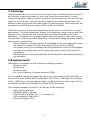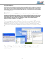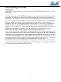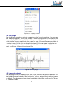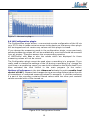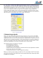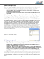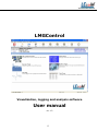
1
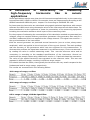
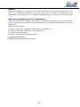
WWW.LECOM.COM.CN
LMGControl
Visualization, logging and analysis software
User manual
(V1.17)
0
WWW.LECOM.COM.CN
Contents
1
2
3
4
5
Overview
Requirements
Installation
Connecting to an LM
LM configuration
5.1 Remote configuration
5.2 Save and load configurations
5.3 Enter and edit scripts
5.4 Create a problem report
5.5 Show hardware and software options
5.6 Enter a new options key
5.7 Reset the LM completely
5.8 Energy measurement and other interval measurements
6 View values live on your PC or prepare for recording
6.1 Starting plugins and viewing measuring values
6.2 Table plugin
6.3 Display plugin
6.4 Plot plugin
6.5 Harmonics plugin
6.6 LM Configuration plugin
6.7.M-n Motor torque and speed determination without
measuring shaft
2
2
3
4
5
5
5
5
5
5
5
6
6
7
7
8
8
9
9
10
7 Measuring projects
8 Recording mode
8.1 Programming events
9 Export recorded data
10 Waveform analysis / Analysis of sampling values
10.1 General information
10.2 Harmonic analysis and frequency analysis up to 1MHz
10.3 Recording of transient events
11 Recommendations for measurements
12 HowTos
12.1 Upgrade the options of your LM
13 Problems
11.1 LM is not automatically connected
11.2 Plugins show error “Cannot connect to LMGControl”
11.3 Recording aborts after some time
11
12
12
13
15
15
15
16
17
17
17
17
17
18
18
11
A Estimation of uncertainty for measuring high-frequency harmonics like
in avionic applications
19
1
WWW.LECOM.COM.CN
1 Overview
LMGControl allows you to control your LM power meter conveniently from your PC
and transfer measuring values for real-time viewing and recording. You can
configure the power meter remotely, save the current configuration on your PC and
load it to your LM later, edit the LM script, display the measuring values live in
different views and record and export them for later analysis. LMGControl can be
used with the LECOM power meters LM95, LM450 and LM500.
LMGControl consists of the main application which controls a collection of plugin
applications. The main application fetches the measuring values, stores them and
exports them. The plugins only view measuring values received by the main
application. Therefore you can close plugins while recording or open new ones to
view the same measuring values differently. This modular design enhances stability,
performance, extensibility:
- When a plugin is not responding it is suspended by the main application while
the rest of the plugins and the main application continue working.
- On modern multi-core processors the main application runs on one processor
core and the plugins can use the remaining ones to fully utilize your PC’s
capabilities.
- More plugins for viewing and analysis are developed to extend the abilities of
the software.
2 Requirements
LMGControl is available for the following operating systems:
- Windows 2000
- Windows XP
- Windows Vista
- for Linux (Debian 4.0) please contact LECOM
For the reliable transfer of measuring values we recommend a CPU with 2GHz or
more and at least 512MB RAM (for Windows 2000/XP) or 1GB RAM (for Windows
Vista). LMGControl requires approximately 20 MB of free hard disk space. For the
recordings we highly recommend to use the NTFS file system.
The interface between LM and PC can be any of the following:
- RS232 serial interface
- IEEE488 (GPIB) interface
- USB to RS232 adapter (cf. 11.1 on page 13)
- USB interface of the LM500
- Ethernet-adapter Z318
2
WWW.LECOM.COM.CN
3 Installation
LMGControl is distributed as a single setup executable which contains all required
files. Just click on the setup executable and follow the instructions on the screen.
Afterwards a shortcut on the desktop and an entry in the start menu are available
to start LMGControl.
Important:
The first time you start LMGControl your firewall may ask you if it should be
blocked from accessing the network. Do not block network access for LMGControl!
LMGControl uses a PC internal network to communication between plugins and
main application and will not work otherwise. When the firewall question
pops up, choose “Unblock” (cf. figure 1).
If you are using the standard Windows firewall you can unblock LMGControl by
opening the “Windows Firewall”, which can be found in the “Control Panel”. Select
the tab ”Exceptions“ and make sure the box in front of the application name
(“LMGControl visualization, logging and analysis software”) is checked (cf. figure
1).
Figure 1: Windows firewall question about LMGControl’s network access. Choose
unblock for LMGControl to work. Firewall settings for LMGControl must allow
network access.
3
WWW.LECOM.COM.CN
4 Connecting to an LM
Important:
For RS232 connection you must configure your LM’s ’IF/IO’ settings to use ’ComA:
OEM Appl’
The first time you start LMGControl there are no previous connections to an LM
available. Therefore you start the interface search by clicking on the search for
devices link or choose Device->Search for devices from the application menu. If
your LM is correctly connected to the PC it can be selected from the list of found
devices. When the search is finished the first found device is automatically
selected if you do not manually select another one. If your LM is not found you
might need to check the IF/IO settings in the LM or the connecting cable (cf.
section 11.1 on page 13). If you have several devices connected to your PC, they
should be displayed one by one. You can select one of them to work with.
LMGControl does not support using more than one LM at a time.
If you are successfully connected to a device, LMGControl will automatically try to
restore this connection every time it is started. As long as you do not change the
interface (e.g. by plugging your USB-adapter into a different port) you will be able
to start working as soon as the application has been started. Of course you can
disconnect from an LM to search for other connected devices on other interfaces.
Just select Device->Disconnect from the application’s main menu.
The device connection is saved with your project, too (cf. section 7). When you
load a project the connection will be restored if the device is available. Therefore
you can have projects using different LMs.
4
WWW.LECOM.COM.CN
5 LM configuration
When LMGControl is connected to your LM, it first goes into configuration mode.
In this mode you can configure your LM using every option available in the Device
menu.
5.1 Remote configuration
While you are using LMGControl, your LM is in remote mode. Therefore you
cannot use the instrument’s controls to configure it directly. A better alternative is
to configure the LM directly from your PC using the menu option
Device->Configure. The remote setup dialog appears which replicates the LM’s
menu screens for configuration. When you enter a new value into one of the fields
it is marked in yellow signifying that the change has not yet been sent to the LM.
This is only done when you press the return/enter key on your keyboard.
Otherwise you can still decide to discard this change by closing the dialog. After
confirming a change the dialog reloads from the LM, because some configuration
options cause changes in the available configuration options.
5.2 Save and load configurations
Once you have configured your LM as needed for your project, you can save the
configuration to a file on your PC. The configuration is downloaded and stored
when you select Device->Save device configuration to file from the menu. The
configuration can then be transferred back to the LM via the menu item
Device->Load device configuration from file.
5.3 Enter and edit scripts
LM power meters can be extended with a scripting language, allowing the users to
compute new values from the measuring values inside the LM. These computed
values can be displayed in the LM’s user-defined menu and transferred to the PC
(e.g. to LMGControl).
LMGControl contains a comfortable editor for the LM scripting language which can
be started via Device->Edit user-defined script in the LM. This editor includes
features like syntax highlighting of the scripting language keywords, tool tips to
display possible parameters and a syntax testing which places the cursor on the
position of an error in your script. More help about the editor and the scripting
language is available in the editor itself (in the Help menu).
5.4 Create a problem report
If you have questions about the usage of the LM and want to contact the LECOM
support it is very helpful if you can provide a problem report. The menu option
Device->Create problem report allows you to enter some data about the set up of
your measurement and then automatically reads important configuration settings
and measuring values from the LM. This information is written to a PDF document
which you can e-mail to LECOM to help our support find a solution for you faster.
5.5 Show hardware and software options
You can display information about your LM including the hardware equipment?
and software options as well as connected clamps. This information is available
via the menu item Device->Show information about LM or by clicking on the LM
icon in the main window.
5.6 Enter a new options key
LM power meters can be upgraded to new options with an activation key. These
can be input by using the wheel on the LM to select the letters. A more
comfortable alternative is to use LMGControl and choose Device->Send a new
options key to the LM from the menu. If you want to upgrade your LM with a new
options key please read the detailed description on this topic which can be found
in section 10.1 on page 13.
5
WWW.LECOM.COM.CN
5.7 Reset the LM completely
If you want to reset your LM to the factory default settings select: Device->Reset
the LM from the main menu Beware that every script formula and user-defined
menu in the LM is deleted While the script is saved
with the configuration on your PC, the user-defined menus can only be saved to
the floppy disk drive of your LM or a plugged-in USB stick Please refer to the
manual of your LM for more information on this topic.
5.8 Energy measurement and other interval measurements
To control the integration of the active energy or other integration values there are
three menu entries in Device- >Interval measurements These are only available
when you are viewing values live in the plugins or performing
:a recording You can start, stop and reset the interval measurements via the
corresponding menu entries. :
6
WWW.LECOM.COM.CN
6 View values live on your PC or prepare for recording
To begin fetching values from the LM you first have to choose one of the plugins
described in the following. Each plugin provides a different view of measuring
values. Only plugins can retreive measuring values. The same values can be
shown in several plugins simultaneously. The number of plugins you can use is
only limited by the PC’s performance. The maximum number of measuring values
that can be fetched depends on the speed of your PC as well as on the bandwidth
of the interface and its transfer rate (e.g. selected baudrate of the RS232
interface).
6.1 Starting plugins and viewing measuring values
Plugins can be started by clicking on their icons in the main window (cf. figure 2)
or selecting a plugin from the Start plugin menu. As soon as a plugin is open
LMGControl switches into interactive mode, where no configuration of the LM is
possible.
To add measuring values to a plugin either use the plugin’s menu (File->Request
value) or click on the “add”
Figure 2: Plugins can be started via the main menu or their icons
symbol in its toolbar. Then a dialog appears which lets you add and remove
measuring values (cf. figure 3). The dialog contains a short description for every
value. If you are looking for a measuring value you can use the search tab to enter
a term to look for in the description or the value names. On the right side the
dialog shows the list of currently retrieved values and lets you remove them from
this plugin. Finally, when you press then start button in the toolbar of the main
application the measuring values are retrieved from the LM. The main application
is minimized to give more screen space to the plugins. While
you are retrieving values you can still open more plugins and add measuring
values to them. As soon as you add a new value the plugin is restarted and begins
viewing again.
7
WWW.LECOM.COM.CN
Figure 3: Adding and removing measuring values of plugin
6.2 Table plugin
The Table plugin allows to view a number of measuring values in tabular form. The
values are arranged in columns in the order in which they were added. By default
the table scrolls when new values are added after a measuring cycle. This can be
changed via View->Follow values in the menu or with the blue arrow icon in the
toolbar.
Figure 4: Table plugin
6.3 Display plugin
The Display plugin shows the current values of the selected measuring values like
the display of the LM. The measuring values can be formatted with different font
faces, sizes, and colors. Additionally, a background color for the window can be
selected. The formatting is controlled via a context menu for each displayed
measuring value. You can open the context menu by right-clicking on a measuring
value.
8
WWW.LECOM.COM.CN
Figure 5: Display plugin
6.4 Plot plugin
The Plot plugin can show a single measuring value’s plot over time. You can use
the “magnifying glass” icon in the toolbar to zoom into the plot. If you want to see
the complete plot double-click in the window or use the Fit graph to window button
in the toolbar to auto-scale both the x- and y-axes. More options are available in
a context menu (right-click on the plot to view it). You can save the plot as an
image to use it in your documents or print it. This command is available in the
menu via Extras->Save plot as image file
Figure 6: Plot plugin
6.5 Harmonics plugin
The Harmonics plugin displays a bar plot of the selected harmonics. Because of
the high differences between the harmonics’ values, a logarithmic scaling is used
by default. The Harmonics plugin is only available if the LM is configured in “Harm”
or “CEHarm” mode.
9
WWW.LECOM.COM.CN
Figure 7: Harmonics plug
6.6 LM Configuration plugin
The Configuration plugin allows:: a convenient remote configuration of the LM via
your PC For this it needs exclusive access to the device so that every other plugin
will be stopped and not receive any values until this plugin is closed.
If you change the measuring mode in the configuration plugin, some previously
selected measuring values will not be available any more and should be removed
from all plugins. Therefore answer the corresponding question
of LMGControl with Yes or else the values which are displayed for these
measuring values will not be correct.
The Configuration plugin cannot be used when a recording is in progress. If you
really need to change the settings of the LM during a recording (e.g. change the
cycle time or a measuring range) you can do this instead on the device itself if you
have activated the local control in the main program (in the menu:
Options->Preferences in the tab: Advanced activate the option enable local
control of LMG ). Beware that changes during a recording Always induce the risk
of inconsistent or undesired measured values For example:: it could be confusing
if a part of the recording contains filtered values while the other part contains
values recorded with a filter turned on.
Figure 8 LM Configuration Module
10
WWW.LECOM.COM.CN
6.7 M-n Motor torque and speed determination without measuring shaft
This plugin can only be used with LM450 and LM500 if the options linked values
(star-to-delta-conversion, option L45-O6 resp L50-O6) and (option L45-O16 resp.
L50-O16) are enabled for your LM. It provides an input form for the data of the
motor to be measured. After the input the LM computes script variables for
motor torque and speed, which can be retrieved and recorded like other script
variables. Further information is available in a separate manual for this module (it
can be found in the Windows start menu under LMGControl
7 Measuring projects
When you have started and positioned some plugins on the screen and added
measuring values to the plugins for a specific measuring task you do not want to
repeat that every time you are performing this measurement. Therefore you can
save all this as a measuring project. In the main window you find the options to
create a new project, save the current project and open a saved project. These
options are available in the menu File and as icons in the toolbar.
The following items are saved in a project:
- the connection to the LM
- the configuration of the LM
- the plugins you have started
- position and size of the plugins’ windows and the main application window
- measuring values for each plugin
- Programmed events for event triggered recording.
Before you load a project make sure that the LM is connected to the PC and ready
so that the connection with LMGControl can be restored and the measuring values
be added to the plugins.
11
WWW.LECOM.COM.CN
8 Recording mode
When you have selected the measuring values in the plugins you can then record
them to hard disc. LMGControl provides three different types of recordings:
- Normal recording: start immediately, record values continuously
- Step recording: start immediately, but only record values of single time
steps when a button is clicked
- Event-based recording: program events, which trigger start and stop of the
recording
Each of these recording types can be started with its button in the toolbar or via
the entry in the Recording menu. If you have chosen event-based recording you
can then program the events. For a detailed description refer to chapter 8.1 on
page 10. Otherwise the recording dialog is displayed immediately listing the
measuring values to be recorded and allowing you to enter a comment to describe
the measurement (cf. figure 9), which will be saved in the recording file. Confirm
it with OK and next input a filename for the recording. As soon as you click on
Save the recording is started. In the case of the step recording the values are
recorded only when you click on the Step record button in the toolbar. Each
recorded value is displayed in the plugins immediately. Once a recording has been
started LMGControl changes into recording mode. In recording mode you can
neither configure the LM nor add new measuring values to the plugins besides the
ones you are recording at the time, but it is still possible to start more plugins to
view the recorded values.
Figure 10: Recording dialog
8.1 Programming events
The following events can be used to control a recording:
- Time: You define a start time and a stop time for the recording using either
PC or LM as time source (cf. figure 11).
- Duration: As an alternative to defining a stop time you can also specify a
duration for the recording (cf. figure 12).
- measuring values: You can define threshold values to be compared with the
measuring values which trigger an event when they are exceeded (cf. figure 13).
- Digital inputs: The states of the digital inputs can be combined with AND
and OR to a logical formula, which triggers an event when it equals TRUE (cf.
figure 8.1).
A recording can only be started and stopped once. Even if you have programmed
several start events only the first event to occur triggers the beginning. After the
recording has been stopped by a stop event it will not be resumed by another start
event.
12
WWW.LECOM.COM.CN
Figure 11: Time as event Figure
12: Duration of recording as event
Figure 13: Measuring value
threshold as event
Figure 14: Logical formula with
digital inputs as event
9 Export recorded data
The recorded measuring values are saved in a binary format, which cannot be
read with a text editor or spreadsheet application. This format is much more
efficient requiring only about half the space compared to a text-based format.
To view the recording you can use LMGControl. The file type for recordings .lcr is
associated with LMGControl so that you can view it by double-clicking on a
recording file. Another possibility is to export the data for further processing in
other applications. LMGControl supports the widely used .csv-format
(comma-separated values), which can be read by every spreadsheet application.
With the export option (which is available in the menu as File->Export recording
when you are viewing a recording) you can select only those values which you
really need in another application. This is especially important as typical
13
WWW.LECOM.COM.CN
spreadsheet applications do not support large text csv-files with more than 256
columns or 65535 rows. The export dialog (cf. figure 9) lets you select the
measuring values from the ones available in the viewed recording. By default, all
values are selected for export. You can change the list by clicking on a measuring
value and one of the buttons add all, add, remove, remove all. The selected
measuring values are exported as columns in the order in which they appear in
the selection list. It is possible to export a value multiple times by adding it more
than once. If you have recorded the harmonics of a channel you will get an
additional choice dialog with the option to specify a range of harmonics and
limiting the export to even or odd harmonics.
Also you can choose a time span from the recording to export. An accurate
timestamp is attached to all recorded measuring values so that LMGControl can
export the values between a start time and an end time which you can input.
Another option is to export not the values of every recorded cycle, but only every
second or third etc value. This is useful if you need a table where the time span
between two values is longer than the longest cycle time of the LM.
For the use with applications that do not support larger data sets you can split the
exported file into several smaller files. As a criterion for the splitting the maximum
number of lines per file or a maximum file size in kilobyte can be chosen.
Important: In some countries the comma is used as decimal separator.
Therefore it must not be used as a field separator in CSV files. LMGControl by
default uses a period as decimal separator. If your other application does not work
correctly with this setting you should change the CSV-separator to semicolon and
the decimal separator to comma and adapt the import settings of the application
respectively.
Figure 15: Export options
14
WWW.LECOM.COM.CN
10 Wave form analysis / Analysis of sampling values
LMGControl can be extended for the analysis of the LM’s sampling values with the
module “Waveform Analysis” (option LMG SUBSCRIPTNBCONTROL
SUBSCRIPTNB W A) which is available separately. This option provides several
recording- and analysis-options:
- Harmonic or frequency analysis is possible up to 1 MHz (with LM500)
exceeding the limits of the internal harmonic analysis of the LM.
- Transient events, which are detected by the LM can be transferred and
collected over longer periods of time for later analysis.
10.1 General information
The waveform analysis can be found in LMGControl’s toolbar (“Sampling values”).
The menu can only be used when no plugin has been opened.
To keep the transfer duration short, only those values from the u- i- and
p-channels are transferred, which you selected The value list is on the right side ::
of the input dialog. The left list contains all available channels and the right list
displays the selected ones. By double-clicking on an entry you can add a value or
remove it, respectively.
10.2 Harmonic analysis and frequency analysis up to 1MHz
Depending on your application it is easier to view the spectral analysis of the
sampling values either as harmonic analysis or as frequency analysis. LMGControl
provides both possibilities to specify the required parameters.
With the harmonic analysis you can either synchronize the fundamental frequency
to any channel of the LM or set a fixed frequency for the analysis. Based on this
fundamental frequency you can then set the number of harmonics and inter
harmonics, which should be calculated.
With the frequency analysis you define a range of frequencies you want to analyze.
The provided step size between the analyzed frequencies is used as the
fundamental frequency.
If you click the button Start recording you will be asked for a file name. The file
containing only the sampling values of the device will get the extension “lcs”. The
moment you click on Save LMGControl starts to record the values. For this
purpose is clears the LM’s sample value memory and then waits for enough
sample values to be recorded. Afterwards the sampling values are transferred and
the harmonics are computed with an FFT algorithm (cf. chapter A on page 19).
These are saved to a second file, which has the same name you have
given, but with the extension “lch”. When the calculation is done this file is loaded
displayed automatically.
15
WWW.LECOM.COM.CN
Figure 16: Harmonic analysis
Figure 17: Frequency analysis
10.3 Recording of transient events
LMs with hardware option (L95-O5, L45-O5 or L50-O5) can search the measured
sample values for transient events, record a detected event and keep it for
viewing and transfer.
LMGControl provides the possibility to save not only a single transient event, but
to continually search for transients and record them to files on your PC.
The configuration of the transient mode can be accomplished via the “LM
Configuration Modul” (cf. page 10). In the transient tab of the sampling values
menu (cf. figure 18) you can change the recording rate for the sample values.
Please note that the LM does not support every recording rate. Therefore a rate
you input is marked in yellow at first and by pressing the enter-key on your
keyboard it is sent to the LM. Then the next possible recording rate is set and
displayed in the input field instead.
Additionally you can limit the values to be transferred. In the dialog you see the
number of values and time in seconds before and after the transient event, which
will be recorded by the LM. By entering your required interval the transfer
duration for a transient is reduced. An approximation of the transfer time is shown
as text below the input fields. During transfer over a transient the search is
stopped and further events which occur during this time are not detected and
recorded by the LM.
Figure 18:
Recording of transients
16
WWW.LECOM.COM.CN
11 Recommendations for measurements
In general, auto-range should not be used for recordings (also cf. the notes on
auto-range in the manual of your LM). When the measuring range changes, which
can occur multiple times in a row in case of high signal peaks, the instrument
requires up to several seconds to settle. During this time there are no sensible
measuring values available. Therefore no new values are computed or displayed.
In this case your recording can contain gaps of several seconds.
Further more it is necessary to know the used measuring range and its usage of
range for the computation of the accuracy of the measurement. As the measuring
ranges can change in auto-range, their values (URNG and IRNG for every
recorded measuring channel) must be requested and recorded, too. These values
can be selected and added like any other measuring values.
Even with fixed measuring ranges it is recommended to record the usage of range
or over range, respectively.
These are the values OVRI for current channels and OVRU for voltage channels.
This allows to calculate afterwards if the measurement has been performed
correctly and the measured values are plausible (usage of range:::::::: neither :::
too small nor over 100% ).
12 HowTos
12.1 Upgrade the options of your LM
LMGControl provides a convenient way to upgrade the software options of your LM.
Select Device->Show information about LMG from the main menu to view your
current options. At the very bottom of the dialog you can find the current options
key. Click on Copy options key to clipboard. Then you can paste the key into an
e-mail in which you order new options from LECOM.
When you receive the new key you can input it in LMGControl and send it to the LM
(Device->Send new options key to LMG). After the successful transfer of the key
the new options will be unlocked.
13 Problems
13.1 LM is not automatically connected
- Ensure that the connecting cable between PC and LM is plugged in correctly.
- LMGControl supports only COM-ports 1 through 9. You can re-assign the
port number in Windows’ device manager.
- If you are using a USB-adapter (USB-to-RS232 (serial) or USB-GPIB
interface) try plugging it out and in again
- Check if the IF/IO settings in your LM are set to either ’ComA OEM Appl.’
or ’GPIB’ (especially it must not say ’Not connected’)
- Wait until search is finished. If the LM was not found, try searching a second
time.
- USB-serial adapters with certain chipsets do not work with multi-core
processors. In this case you have to use another interface.
17
WWW.LECOM.COM.CN
13.2 Plugins show error “Cannot connect to LMGControl”
You must configure your firewall to allow (PC-internal) network access for
LMGControl. See chapter 3 on page 3 for details.
13.3 Recording aborts after some time
The transfer of data from LM to PC requires real-time processing. For stable
long-term recording not to loose any data the PC should have enough resources
available. Especially the following items are important:
- The energy saving options must be disabled or else your PC will go into
energy saving mode after you are away for some time.
- Disable your screensaver, too, because it could disturb the data transfer.
- The background checking of your virus scanner can slow down the writing to
hard disc, too.
- If you are recording directly to a network drive it is possible that the
network speed is not sufficient.
18
WWW.LECOM.COM.CN
A
Estimation
of
uncertainty
for
measuring
high-frequency
harmonics
like
in
avionic
applications
Some applications require more than the 100 harmonics supplied directly by the measuring
instruments LM95, LM450 or LM500. For example, there are measurements according to the
AIRBUS standards ABD0100 part 1 chapter 8 or according to EUROCAE ED-14D.
In these cases the harmonics are calculated using speed-optimized algorithms with externa
software like LMGControl using the sample values of the instrument as calculation base. For
these standards it is also important to know the uncertainty of the measuring equipment
including the evaluation software which is part of the measuring chain.
For the purpose of estimating the uncertainties of this calculation method we generated two
voltages using two coupled arbitrary waveform generators. One generator was used for a
416.6Hz fundamental which we applied to the voltage channel. This signal was used for:::
the synchronization of the instrument.
With the second generator we produced several harmonics (one at a time, always same
amplitude) which we applied to the shunt input of the current channel. The main problem
was the accuracy of the generators which was not sufficient for this measurement. To
eliminate this problem the signal was measured in two different ways. First we measured it
by reading the value in normal measuring mode. This was the reference value and its
uncertainty is according to the standard specifications of the instrument. Second we
transferred the sample values using LMGControl version 1.13 and calculated the harmonics.
The value of the applied harmonic was compared to the reference value. This test was
repeated in different ranges, resulting in different range usages.
This should simulate the effect, that typically the harmonics are very small compared to the
fundamental and its range usage, respectively.
The results are summarized in the following tables:
10% usage of range, no filter
10% usage of range, no filter
0.3% usage of range, 150kHz signal filter
19
WWW.LECOM.COM.CN
Results
Notably, the usage of a range has very small influence on the uncertainty, as well as the
filters. The frequency-dependent errors are quite small. Therefore the influence of the
computation on the final result is negligible compared to the uncertainty of the instrument.
Necessary equipment for this application
Following you find the necessary equipment in minimum configuration for this application.
Further options and equipment may be necessary to meet the requirements for a concrete
application.
Measuring Instrument:
a) LM95 + option O1 (restricted usage due to bandwidth) or:
b) LM450 (restricted usage due::: to bandwidth) or
c) LM500 (recommended):
Software “LMGControl“ with option LMG:
SUBSCRIPTNBCONTROL
SUBSCRIPTNBWA (waveform analysis):
20