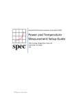
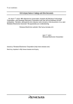
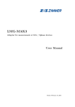
1
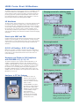
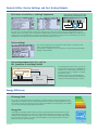
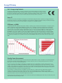
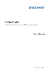
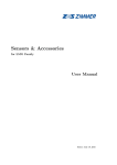
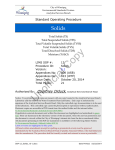
Precision Power Meter LMG95
The most precise in its class.
LMG95 e 03.11
•
•
•
•
Basic accuracy 0.015% of reading + 0.01% of range
Precision range DC...500kHz
Analysis of devices and components in switched or modulated operation
Harmonics and flicker according to EN61000-3-2/-3/-11/-12
LMG95. Precise. Direct. All Waveforms.
The LMG95 single-phase precision power meter is an outstanding product
in the proven LMG series of ZES ZIMMER® precision power measuring
devices. Highly accurate continuously gapless signal measurement and
processing, ergonomic operation and presentation of the results, interfaces with high data rates for efficient system applications – these are
the performance features which distinguish the LMG95.
Charging current of a switching power
supply
All Waveforms
The high precision power measurements on components and devices that
are required in development, quality assurance and manufacturing can
be performed with ease, independent of whether the current and voltage
are sinusoidal or distorted, whether the load is linear or not, or whether
the circuit works in a chopped, pulsed or another modulation mode.
The extended possibilities of synchronization on the periodicity of the
measured signal always produce distinct and stable measurement displays
and results.
Waveform of
charging current
Amplitude spectrum of the current
harmonics with CE evaluation in
accordance with class A
Direct up to 600V and 20A
Isolated measurement inputs with direct measurement ranges up to 600V
(1600Vpeak) and 20A (960Apeak for the measurement of inrush currents)
and the input for current measurements using a shunt or other transducer
measure the incoming measurement signals exactly and without any
aberrations.
Phase-angle control
0.015% of Reading + 0.01% of Range
With a basic accuracy of 0.025% is this the most precise instrument in
its class and therefore it is used as a reference device for energy meters,
power meters, power measurement transformers and trms meters for
current and voltage.
Waveform of
current
Harmonics and Flicker in Full Compliance
with EN61000-3-2/-3/-11/-12
The harmonic analysis in full compliance with the EN61000-3-2/-12
standard is already available in the basic unit. The flicker meter in
compliance with EN61000-4-15 for the measurement of flicker (voltage
variations) and with EN61000-3-3/-11 is available as an option. These
two functions also considerably extend the possible applications of
the LMG95 in R&D laboratories. If suitable stable voltage sources are
available, tests for CE compliance can be performed in accordance with
EN61000-3-2/-3/-11/-12.
Table of the current harmonics with
limits in accordance with class A
PWM frequency inverter
Analyzers in CE Test Systems
The LMG95 is used as an
analyzer in CE test systems
to test electrical devices on
harmonics and flicker and their
effect on mains.
The ZES ZIMMER® test system
CE-Test61k is usually equipped
with a precision power meter
LMG500 for 3-phase application
or with a LMG95 for singlephase applications.
Components can also be
ordered and used separately,
easy integration of customer
owned power sources.
Line voltage
against artificial
midpoint
Measurement of the amplitude spectrum of the voltage harmonics in the
HRM100 mode. An increase in the 47th
and 49th, the frequency of the fundamental amounts to fn/47=26.25Hz
Transparency Through Real-time Visualization in the Time and Frequency Range.
Electronic transformer
Electronic 12V transformer to supply a halogen lamp.
Amplitude modulated 150 kHz carrier with 100Hz envelope.
Burst firing control of a hot-air fan
Harmonic analysis
Amplitude spectrum with the help of the HRM100 harmonic analysis. The burst fire presents a 1.56Hz modulation of the carrier
(50Hz mains voltage). The DC component of the spectrum results from the blower motor in half-wave operation.
The extended “X-Trig” trigger mode detects the 1.56Hz periodicity which is used for synchronization.
Flicker measurement
Using the plot function, the half-wave
trms values Ul are plotted over time
(lower curve B). There are irregular
sags of about 8V. The momentary flicker
Pmom resulting from these changes is
visualized by curve A.
Switch-on current of a fluorescent lamp ballast measured in the transient mode
Switch-on current of a fluorescent lamp
ballast. The iron is not saturated.
Inrush current of a transformer
In the moment when the currentless,
non-magnetized transformer is switched
on, a multiple of the nominal current is
required to build up the necessary flux.
The iron goes rapidly into saturation.
Here Iinr/Itrms=12.9.
Formula Editor, Device Settings and Fast Analog Outputs.
Core losses at small cos ϕ and high frequencies
(with optional 500kHz precision bandwidth and delay compensation to 4ns)
I
˜
U
The magnetizing current I flowing in the primary winding is fed into the current input of the LMG95, and the induced voltage at the open secondary winding is fed into the voltage input. In this way, only the core losses (magnetizing losses) are
measured, and not the copper losses. The half-wave rectified voltage value, also measured with the LMG95, is a measure of the
voltage time area, and therewith for the induced flux. With the formula editor, the values for a B-H characteristic curve can be
calculated from the measured electrical values and the geometrical data of the core.
Device settings
Up to 8 device settings can be stored with a name, details of the EUT etc. with
“Save” and retrieved again with “Recll”.
This provides for a high level of user convenience if measurements are made alternatively on different EUTs.
Fast analog outputs u(t), i(t), p(t) for
HIL (hardware-in-the-loop) control
LMG95
Ext. Shunt I
Input
I*
u(t), i(t), p(t)
U U*
~
EUT /
Simulation
Output
The instantaneous values of u(t), i(t), p(t) can
be output with a sample rate of 100kSample/s.
Via the process signal interface the values can
be send to the EUT or a simulation for testing
the dynamic control.
Fast HIL controls require the instantaneous
values rather than values that are delayed and
averaged over the measuring cycle (≥ 50ms).
Energy Efficiency
EU energy label
Since 1988 household appliances like refrigerators or washing machines must be labeled with the EU
energy label (see picture). The green range ‘A’ indicates the most efficient energy utilization, the opposite is true for the red range ‘G’. Precise power meters like the LMG95 are indispensable for the validation of the chosen label by independent test laboratories.
Energy Star
The Energy Star originally started in Northern America and has spread all over the world. For being
marked with the Energy Star, a product has to meet a defined threshold. For example, in the USA a
newly introduced refrigerator has to save 20% relative to the current maximum admissable consumption. A precise power meter is necessary for both the R&D of a new product and tests in the field
whether it meets the specified savings.
Energy Efficiency
EuP - Energy using Products
The directive 2005/32/EC defines ecodesign requirements for household appliances and office machines.
It regulates the admissible energy consumption while a product is in use as well as the energy consumption during its fabrication and its disposal. In addition, the directive addresses further ecological aspects
like saving resources through an economic material usage and avoiding hazardous substances.
Green IT
To save the environment, information technology and communications equipment has to economize on energy and resources
throughout its life cycle. To meet these requirements, it is important to optimize the equipment during the development stage.
For this purpose, the precision power meter LMG95 is a helpful tool for every R&D engineer.
SPECpower_ssj2008
The Standard Performance Evaluation Corporation (SPEC) is a working group of well-known manufacturers of computer systems.
SPEC has created the industry standard SPECpower_ssj2008. This is a method for measuring computing power, electrical power consumption and energy efficiency. The abbreviation ssj (server side JAVA) refers to the workload on the server which is
reduced in steps of 10% starting at 100% (full utilization) to zero (no load) (see picture). SPECpower_ssj2008 requires that a
power meter records the power consumption with a time resolution of 1 second and logs the data into a control system.
ZES ZIMMER® power meters (LMG95 for single-phase, LMG450 and LMG500 for multi-phase applications) meet this standard.
Due to their range dynamic, they are able to precisely capture changes of the load, e.g. when changing to another workload.
Moreover, they do not only transmit the measuring value, but also the respective measuring range and its utilization, so that
the measuring uncertainty can be calculated for each period. ZES ZIMMER® LMG-series power meters have been approved by
SPEC.
Source: © 2007-2009 Standard Performance Evaluation Corporation (SPEC), reprint with permission.
Source: Article „The measurement of the PC world“, c‘t 2008, edition 4.
Standby Power Measurement
The regulation 1275/2008 released by the European Commission defines limits for power consumption of household appliances
for the „off“-mode and a defined standby mode. From January 2010 these limits are 1W respectively 2W, and from 2014 the
limits will be cut to half to 0.5W respectively 1W.
In case of an ohmic load a voltage of 230V and an acceptable power loss of 0.5W implies a current of about 2.2mA. 2% accuracy of 0.5W equals an uncertainty of 10mW, which seems to be easy to handle by most power meters. However, in practice
standby circuits usually have a low power factor and a high crest factor. Assuming that the power factor is 0.1, which is rather
common for applications like refrigerators or PC monitors, the current is 10 times larger than in the example above, and hence
the measuring range also needs to be increased by this factor.
The crest factor of a state-of-the-art „zero-watt PC“ can reach values of 6 or higher due to its rectifier with smoothing
capacitor. These peaks superimpose the capacitive reactance current and yield the main contribution to the standby
consumption, and therefore the measuring range has to be increased by an additional factor. In this example, the measuring
range must measure a current of 22mA, with a peak value of 130mA.
The low power factor and the high crest factor can increase the measuring uncertainty by the order of two, and hence the power
meter must have a basic accuracy of 0.03%.
Energy Efficiency
The LMG95 meets these high-end requirements.
LMG95
Ext. Shunt I
Input
I*
To optimize the scaling and to protect the unit, use
an additional external shunt (L95-SH-xxx-P). For low
currents, use the wiring for current-correct measurement. (See also into our application note #102 “Measurement of Standby Power and Energy Efficiency”.)
U U*
Ext. Shunt
LMG-SHxxx-P
L
AC Power
Supply
230V
N
The ZES ZIMMER software CE-Test-Standby in combination with a precision power meter LMG95 or LMG500
measures the standby consumption according to the
standard IEC/EN 62301. CE-Test-Standby configures
and monitors the measuring devices, sets the test
sequence and generates a test protocol in accordance
with the standard.
EUT
PE
Current-correct measurement with external shunt LMG-SHxxx-P
Technical Data
Voltage measuring ranges
Rated range value /V
Permissible trms value /V
Permissible peak value
for full scale /V
Overload capability
Input resistance
6
7.2
12.5
12.5
14.4
25
25
30
50
60
60
100
130
130
200
250
270
400
400
560
800
600
720
1600
0.15 0.3
0.6
1.2
0.3
0.6
1.3
2.6
0.469 0.938 1.875 3.75
2.5
5.2
7.5
5
10
15
10
21
30
20
21
60
Options for modification of
600V-standard-measuring input:
Options:
Measuring ranges:
L95-07-2
25mV...3V
L95-07-3
100mV...12V
L95-07-4
400mV...60V
L95-07-5
12V...650V (3200Vpk)
1500V for 1s
1MΩ, 20pF
Current measuring ranges
Rated range value /A
Permissible trms value /A
Permissible peak value
for full scale /A
Overload capability
Input resistance
120
21
120
240
21
240
480
21
480
960
21
960
Options for modification of
20A-standard-measuring input:
Options:
Measuring ranges:
L95-08-1
0.6mA...80mA
L95-08-2
10mA...1.2A
L95-08-3
40mA...5A
160A for 1s
5mΩ
Voltage inputs for current measuring
with shunt / transducer
Rated range value /V
Permissible trms value /V
Permissible peak value
for full scale /V
Overload capability
Input resistance
0.03
0.06
0.0977
0.06
0.13
0.1953
0.12
0.27
0.3906
0.25
0.54
0.7813
0.5
1
1.563
1
2
3.125
2
4
6.25
4
8
12.5
250V for 1s
100kΩ
Measuring range selection
Auto, manual or remote control
Isolation
Current and voltage path are isolated against each other and may float against earth with 1000V/CAT III
Measuring method
Simultaneous sampling of the current and voltage inputs and A/D conversion of the instantaneous values (100kHz).
Memory for up to 2.106 sampling values
Measuring cycle, synchronization,
averaging
For measurements of the trms values for current, voltage and active power, the measuring cycle time is adjustable in the range
from 50ms to 60s. In each measuring cycle gapless 100kHz sampling and evaluation. The synchronization can be performed on the
measuring signal, the fundamental harmonic, the envelope, the mains or an external signal. Averaging over 1 to 1000 measuring cycles
Measuring uncertainty (Standard version)
± (% of measuring value + % measuring range)
Measuring
uncertainty
DC
0.05...15Hz
15...45Hz
45...65Hz
65Hz...1kHz
1...3kHz
3...15kHz
15...50kHz
Voltage
0.02+0.06
0.02+0.04
0.015+0.03
0.01+0.02
0.015+0.03
0.03+0.06
0.1+0.2
0.5+1.0
Current
0.02+0.06
0.02+0.04
0.015+0.03
0.01+0.02
0.015+0.03
0.03+0.06
0.1+0.2
0.5+1.0
Shunt voltage
input
0.02+0.06
0.02+0.04
0.015+0.03
0.01+0.02
0.015+0.03
0.03+0.06
0.1+0.2
0.5+1.0
Active power
0.03+0.06
0.035+0.04 0.025+0.03 0.015+0.01
0.025+0.03
0.05+0.06
0.2+0.2
1.0+1.0
Measuring uncertainty (500kHz version, Option L95-O6-1)
± (% of measuring value + % measuring range)
Measuring
uncertainty
DC
0.05...15Hz
15...45Hz
45...65Hz
65Hz...1kHz
1...3kHz
3...15kHz
15...100kHz
100...200kHz
200...300kHz
300...400kHz
400...500kHz
Voltage
0.02+0.06
0.02+0.04
0.015+0.03
0.01+0.02
0.015+0.03
0.025+0.05
0.03+0.06
0.1+0.2
0.5+1.0
1.0+2.0
3.0+3.0
4.0+4.0
Current
0.02+0.06
0.02+0.04
0.015+0.03
0.01+0.02
0.015+0.03
0.025+0.05
0.03+0.06
0.1+0.2
0.5+1.0
1.0+2.0
3.0+3.0
4.0+4.0
Shunt voltage
input
0.02+0.06
0.02+0.04
0.015+0.03
0.01+0.02
0.015+0.03
0.025+0.05
0.03+0.06
0.1+0.2
0.5+1.0
1.0+2.0
3.0+3.0
4.0+4.0
Active power
0.03+0.06
0.035+0.04
0.025+0.03
0.015+0.01
0.025+0.03
0.04+0.05
0.05+0.06
0.2+0.2
1.0+1.0
2.0+2.0
6.0+3.0
7.0+4.0
Technical Data
Measuring uncertainty of cos ϕ
Measuring uncertainties based on:
Other values
1. sinusoidal voltage and current
2. ambient temperature 23 ± 3°C
3. warm up time 1h
4.
5.
definition of power range as the product of
current and voltage range, 0 ≤ IλI ≤ 1, λ = P/S (power factor)
calibration interval 12 months
All other values are derived from the values for current, voltage and active power. Accuracies for the derived values depend on
the functional relation (e.g. S = I * U, ∆S/S = ∆I/I + ∆U/U)
Internal time base
±100ppm
Frequency measuring
0.05Hz...500kHz ±0.01% of measuring value, measuring channel selectable
Display of measured and computed values
Representation
With standard abbreviation of measured magnitudes, numeral values 6 digits (0...999999), with sign, decimal point and unit
(e.g. Itrms 0.73851mA), 4 to 8 values can be displayed simultaneously, selectable via default or user defined menus
Voltage, current
Trms value, peak values (min, max, pp), rectified value (rect), mean value (dc), trms value of ac component (ac),
form factor, crest factor
Power
Active power (P), reactive power (Q), apparent power (S), phase angle (ϕ), power factor (λ)
Impedance
Amount (Z), real and imaginary part of resistor in serial equivalent circuit
Integrated values depending on
the measuring time
Energy, charge
Date and time, measuring time
Adjustable parameters
The integration can be controlled manually, automatically using start and stop times, via external trigger or remote
controlled via computer interface
Active energy (Ep), reactive energy (Eq), apparent energy (Es), charge (q)
Current date (day, month, year) with time (hours, minutes, seconds), accu buffered real time clock, start time for measurement,
running measuring time, on-time, each with days, hours, minutes, seconds
Scaling factors for external shunt, current and voltage transducer
Synchronization
Synchronization is made on the periodicity of the measured signal. Periodicity can be determined by the signals u(t), i(t), p(t),
u²(t), i²(t), each of them can be adapted with selectable filters. By this stable displays also with pulse width modulated signals
(e.g. frequency inverter) and amplitude modulated signals (e.g. electronic ballast). Synchronization also by „Line“ and „External“
Scope function
Graphical representation of sampled values (waveform of the signal)
Plot function
Time diagram of calculated values, e.g. trms value and power
Harmonic analysis CE-Hrm
Analysis of current and voltage up to the 40th harmonic (total of 41 with DC component), fundamental in the range
45Hz to 65Hz. Analyzer in accordance with EN61000-4-7 with evaluation in full compliance with EN61000-3-2/-12
Harmonic analysis HRM100
(Option L95-O10)
Analysis of current, voltage and active power up to the 99th harmonic (total of 100 with DC component, max. 10/50kHz),
fundamental in the range 0.1 Hz to 1.2 kHz; with adjustable divider (1...50), a new fundamental can be set as a reference, for
example to determine interharmonics
Flicker measuring (Option L95-O4)
Flicker meter in accordance with EN61000-4-15 with evaluation in accordance with EN61000-3-3/-11
Memory extension (Option L95-O11)
Memory extension for scope function up to 4 million samples of U, I and P. Sample values available via interface
Transients – monitoring and storing
(Option L95-O5)
Storing and graphical displaying of transients with a resolution of 10µs, memory extension (L95-O11) is included. Storing depth
is 4 Millions sample values, selectable recording duration from 0.05 to 60 seconds. Adjustable pre-trigger, different possibilities
of triggering
Computer interface (Option L95-O1)
Remote control
Output data
Transfer rates
Interfaces: RS232 and IEEE488.2, only one interface can be used at the same time
All functions can be remote controlled
Output of all displayable data possible, data formats of all interfaces are the same, SCPI command set
RS232: max. 115200 Baud, IEEE488.2: max. 1MByte/sec
Printer interface
(included in Option L95-O1)
Parallel PC-printer interface with 25 pin SUB-D socket
for printing of values, tables and graphics
Processing signal interface
(Option L95-O3)
25 pin SUB-D socket:
4 analog inputs for registration of auxiliary quantities (16bit, ±10V)
4 analog ouputs (16bit, ±10V) for output of:
• various measure values and operands; updated at the end of each measuring cycle
• signal samples (i,u,p), synchronous to the 100kHz sampling frequency
4 digital inputs for registration of status
4 digital outputs to signal states and alarms
1 input for frequency (0.1Hz...500kHz) and direction (e.g. of motors)
1 power supply output 12V/50mA
Inputs and outputs are isolated group wise against each other and against the other electronics (testing voltage 500V)
Other data
External synchronization/trigger
Isolated interface for external control of measurement cycle and integration times, outputs for status signals about the actual measuring
Service RS232 interface
For installing options, firmware and for instrument diagnosis
Auxiliary power supply output
+15V/0.4A and -15V/0.2A for external transducers
Dimensions/weight
Desktop case, (w)320mm x (h)147mm x (d)274mm, subrack 84PU, 3HU, (d)274mm, about 5.5kg
Safety regulation
EN61010-1, protection class I, overvoltage class III
Electromagnetic compatibilty
EN61326-1, EN61000-3-2, EN61000-3-3
Protection class
IP20 acc. to EN60529
Operation temperature, storage temperature 5...40°C, -20...+55°C
Supply
90...250V, 45...65Hz, about 30W
Measurement Accesories and Extensions
„Plug N‘Measure“ current sensors for extended current ranges up to 10000A
Precision DC
Precision AC
Clamp on CT
Wideband AC
Low-cost Hall
Shunt for standby measurements
0.02%
0.02%
0.15%
0.25%
0.3%
0.15%
DC...1MHz
15Hz...5kHz
2Hz...50kHz
30Hz...1MHz
DC...200kHz
DC...100kHz
0.8A...5000A
5A...10000A
0.3A...3000A
10A...1000A
0.3A...2000A
0.15mA...1A
HF-differential transformer with load resistor for almost reactionless measurement
of current, e.g. at discharge lamps.
Technical data, information and selection guide in the user manual
„ZES Sensors and Accessories“ (available on request and at www.zes.com).
Precision high voltage divider
Precision high voltage divider for 3/6/9/12/30kV up to 300kHz, 0.05%.
Negligible phase error, therefore best suited for wideband power measuring.
- 1-channel HST for single ended voltages
- 2-channel HST for floating voltages (difference measuring)
- 3-channel HST for three phases systems (inverters)
Power quality analysis in railway technology and medium-voltage
systems. Insulation diagnostics by tan δ measuring down to
0.1Hz. Suitable for outdoor application (IP65) with high overvoltage.
Other accessories and special versions/designs
L95-Z318
RS232 Ethernet converter 10/100Mbit
KR-L95
Calibration certificate
ISO9000 traceable
LMG-MAK1, LMG-MAS1
U/I measuring adapter for safety plugs
LMG95-1HE
Precision Power Meter LMG95,
1 RU-flat case without display and
keyboard
L5-IOBOX-S /-F
Adapter (rail mounting) for easy
connection of process signals, including
2m connection cable
WR-24-230
Inverter 24VDC to 230VAC/50Hz for
supply of LMG instruments
L95-Z01
Kit to mount LMG95 into industrial cabinet
L95-Z09
Measurement input sockets on rear of the
device, e.g. industrial cabinet
LMG95 application software (optional)
LMG-CONTROL-B
PC software for data transfer, configuration and visualization. Modular design. Saves and loads device configurations. Interactive mode to
set up a measurement. Recording and logging of data with timestamp accurate to the milliseconds. Analysis modules for different
applications and evaluations. Basic version is free of cost and available at www.zes.com.
LMG-CONTROL-WA
Additional module for LMG-CONTROL, logging and analysis of all sampling values of the LMG, harmonic analysis up to 50kHz, frameanalyser,
recording of transients.
CETEST61k-SOFT
Control/data logging/evaluation software for conformity tests of harmonics and flicker according to EN61000-3-2/-3/-11/-12 with the LMG95
CETEST61k-SW-O1
Option O1 to CETEST61k-SOFT, harmonics analysis 2kHz to 9kHz according EN61000-4-7 annex B
CE-Test Standby
PC software for standby power measuring according to EN/IEC62301
LabVIEW-Driver
LMG95 driver for LabVIEW 8.2, for RS232- and IEEE488.2-interface, with software examples. Driver is free of cost.
Subject to technical changes, especially to improve the product, at any time without prior notification.
United States (subsidiary)
ZES ZIMMER®, Inc.
44 Grandville Ave. SW • Suite 360
Grand Rapids • MI 49503-4064
Tel. +1 760 550 9371 • [email protected]
Germany (headquarter)
ZES ZIMMER® Electronic Systems GmbH
Tabaksmühlenweg 30 • D-61440 Oberursel
Tel. +49 6171 62 8750 • Fax +49 6171 52086
www.zes.com • [email protected]