1
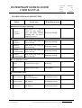
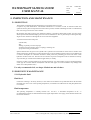
DOC. NO. PAGE. WATERTIGHT SLIDING DOOR USER MANUAL WTDO-055 1/21 REV. DATE. 0 05-09-21 USER MANUAL 0 ’03. 12. 15 Issued for Final Jun Sik Noh Hee Soo Noh Seong Moon Park Rev. No. Date Description Prepared Checked Approved ELECTRO-HYDRAULIC OPERATED WATERTIGHT SLIDING DOOR TEL : 82-55-345-6110 BY Controls, Inc. FAX : 82-55-345-6115 E-mail : [email protected] #850-2, Cheongcheon-Ri, Chillye-Myon, Kimhae-City, Keongsangnam-do, Korea WATERTIGHT SLIDING DOOR USER MANUAL DOC. NO. PAGE. REV. DATE. WTDO-055 2/21 0 05-09-21 INDEX 1. INTODRUCTION ---------------------------------------- 3 1.1 General 1.2 Safety Precaution -------------------------- 3 -------------------------- 3 2. CHECKS ----------------------------------------4 2.1 Visual Check 2.2 Power Pack -------------------------- 4 -------------------------- 4 3. OPENING DIRECTION ---------------------------------------- 5 4. OPERATION DESCRIPTION ---------------------------------------- 6 4.1 Local Operation 4.2 Indication & Alarm System -------------------------- 6 --------------------------- 7 5. INSPECTION AND MAINTENANCE 5.1 Inspection 5.2 Preventive Maintenance 5.3 Inspection and Service Intervals 6. TROBLE SHOOTING -------------------------------------- 8 ------------------------- 8 ------------------------- 8 -------------------------- 10 -------------------------------------- 11 7. DISASSEMBLY, REASSEMBLY AND REPAIR 7.1 Hand Pump 7.2 Hydraulic Manifold 7.3 Hydraulic Cylinder 7.4 Door Seal 7.5 Accumulator 7.6 Pressure Switch 7.7 Proximity Switch ------------------------------ 15 ------------------------- 15 -------------------------- 15 -------------------------- 15 ------------------------- 16 -------------------------- 16 ------------------------- 17 ------------------------- 17 8. LUBRICANT AND OIL CHART ------------------------------------- 18 9. SPARE PART LIST ------------------------------------- 19 10. WORLD WIDE NETWORK ------------------------------------- 20 11. EQUIPTMENT INFORMATION ------------------------------------- 21 TEL : 82-55-345-6110 BY Controls, Inc. FAX : 82-55-345-6115 E-mail : [email protected] #850-2, Cheongcheon-Ri, Chillye-Myon, Kimhae-City, Keongsangnam-do, Korea WATERTIGHT SLIDING DOOR USER MANUAL DOC. NO. PAGE. REV. DATE. WTDO-055 3/21 0 05-09-21 1. INTRODUCTION 1.1 GENERAL "BY Controls" watertight sliding doors are manufactured to your special requirements and to the SOLAS. Every door is factory tested and adjusted. On site installation is therefore limited to welding of the frame into the bulkhead and connection of the electric and hydraulics. The door is approved by DET NORSKE VERITAS. The BY Controls watertight sliding door, classฌ, is an electric/hydraulic-operated sliding door. Standard Class ฌ Each door has an electric driven hydraulic power pack complete with hydraulic accumulator, junction boxes for electric power, signals to/from Wheelhouse, alarm bell, flashing lights, hydraulic cylinder, hydraulic switches, solenoid valve and manual hydraulic hand pump with levers. The door has operating lever. The main principle of the door are: Mimic panel / control panel : A mimic panel is located at the control station(wheelhouse). It gives door location, door status and has control switches. Remote control : Each door can be closed from the control station. The door has a 5~10 second delay with local alarm before moving. The doors in remote closing mode may still be operated locally, however they will close automatically after use. Local operation : Local operation can be operated form both sides of the door by the operating lever. Local manual operation : In case of no electric or hydraulic power, it is possible to operated the door from both sides using the manual hand pump and operating lever. 1.2 SAFETY PRECAUTIONS 1.2.1 Hydraulic System Installation and maintenance procedures must be performed by qualified personnel only. For safety reasons, no pipe connections or components may be loosened while the hydraulic system is under pressure. Always switch off the pumps and depressurize the accumulators before starting any work on the hydraulics. Never work with oily hands. 1.2.2 Electrical System Installation and maintenance procedures must be performed by qualified personnel only. Use extreme care when troubleshooting or performing maintenance tasks on installation parts which use high voltages. As a precautionary measure, use only one hand when servicing electrically live equipment. Use caution when overriding interlocks to trouble shoot. Remove all power from the system, before starting a maintenance procedure, to prevent unexpected door operation. Always verify that power is shut-off before connecting or disconnecting cables. TEL : 82-55-345-6110 BY Controls, Inc. FAX : 82-55-345-6115 E-mail : [email protected] #850-2, Cheongcheon-Ri, Chillye-Myon, Kimhae-City, Keongsangnam-do, Korea WATERTIGHT SLIDING DOOR USER MANUAL DOC. NO. PAGE. REV. DATE. WTDO-055 4/21 0 05-09-21 1.2.3 Warning Emergency closing, commanded from the control station, will automatically close all open doors with warning signals. If power to both alarm and system fails at the same time, the open doors will automatically close without warning signals. 2. CHECKS Before starting up the operation of the door, the following points must be checked. 2.1 VISUAL CHECK Door system must be checked for fluid leaks, damage and dirt. - Repair any leaks or damage and remove dirt. - Checked for looses part, pipes and fittings. - Checked for damaged or stretched cables. 2.2 POWER PACK - Checked the fluid oil tank levels by the level inspection stick. - The hydraulic pump is started by pushing on the switch in local control box and at the same time checked control the hydraulic pressure by the pressure gauge with bore hose. - The pressure will rapidly increase up to pre-charged accumulator nitrogen pressure about 65bar and then continue to normal working pressure. x Relief valve : 210bar x Low-pressure switch for pump motor-on control : 150 bar x High-pressure switch for pump motor-off control : 180 bar x Low-pressure switch for alarm signal : 65bar - Recommended hydraulic oil : Mineral oil ISO VG 32 TEL : 82-55-345-6110 BY Controls, Inc. FAX : 82-55-345-6115 E-mail : [email protected] #850-2, Cheongcheon-Ri, Chillye-Myon, Kimhae-City, Keongsangnam-do, Korea WATERTIGHT SLIDING DOOR USER MANUAL DOC. NO. PAGE. REV. DATE. WTDO-055 5/21 0 05-09-21 3. OPENING DIRECTION TEL : 82-55-345-6110 BY Controls, Inc. FAX : 82-55-345-6115 E-mail : [email protected] #850-2, Cheongcheon-Ri, Chillye-Myon, Kimhae-City, Keongsangnam-do, Korea WATERTIGHT SLIDING DOOR USER MANUAL DOC. NO. PAGE. REV. DATE. WTDO-055 6/21 0 05-09-21 4. OPERATION DESCRIPTION 4.1 OPERATION SYSTEM OPEN R E M O T E CLOSE ͅ IN THE WHEELHOUSE Impossible ൯ Closing of one door : Normally the selector switch for door will be in "LOCAL CONTROL". By turning the switch to "DOOR CLOSED" position, which shall automatically close that, is open. C O N T R O L ͅ LOCAL MODE L O C A L C O N T R O L When the lever is activated by turning When the lever is activated by turning approximately 20 degree towards door opening approximately 20 degree towards door closing direction the door will go to open position. direction the door will go to close position. ൯ If the lever is turned to open and close position, the door will move until full open/close. The lever mounted with a return spring, so when operating power released, the lever return to the neutral position and the door will stop. ͅ CLOSED MODE By activating the operating lever, the door shall The door should be closed automatically upon be locally opened with automatic closure. release of the local control mechanism. ͅ EMERGENCY OPERATION Turning the lever towards door opening and When the door is opened that it can be closed by simultaneously activating the hand pump can activating the hand pump open the door when the door is closed. TEL : 82-55-345-6110 BY Controls, Inc. FAX : 82-55-345-6115 E-mail : [email protected] #850-2, Cheongcheon-Ri, Chillye-Myon, Kimhae-City, Keongsangnam-do, Korea WATERTIGHT SLIDING DOOR USER MANUAL DOC. NO. PAGE. REV. DATE. WTDO-055 7/21 0 05-09-21 4.2 INDICATION & ALARM SYSTEM Status Local area Wheelhouse area h In the case of remote operating shall sound 5~10 seconds before the door begins to Closed 11 move and shall continue Red lamp flashing by power sounding until the door is completely closed h In the case of local operating 21 Closed by power Shall sound only when the Red lamp flashing door is moving 22 Opened by power Shall sound only when the Red lamp flashing door is moving 23 Closed by hand pump Shall sound only when the Red lamp flashing door is moving 24 Opened by hand pump Shall sound only when the Red lamp flashing door is moving h Door open/close status 31 Open Identification at sight Red lamp 32 Close Identification at sight Green lamp h System failure status 41 Loss of power Red lamp on (Power availability) Red lamp & alarm 42 Low pressure Red lamp on Red lamp & alarm 43 Low level Red lamp on Red lamp & alarm TEL : 82-55-345-6110 BY Controls, Inc. FAX : 82-55-345-6115 E-mail : [email protected] #850-2, Cheongcheon-Ri, Chillye-Myon, Kimhae-City, Keongsangnam-do, Korea WATERTIGHT SLIDING DOOR USER MANUAL DOC. NO. PAGE. REV. DATE. WTDO-055 8/21 0 05-09-21 5. INSPECTION AND MAINTENANCE 5.1 INSPECTION The hydraulic equipment has been designed for a long trouble free service life. It requires very little maintenance. Nevertheless maintenance is essential in order to maintain trouble free operation because practical experience has shown that up to 80% of faults and damage are due to contamination, lack of servicing and incorrect choice of fluid. By remaining alert and by paying close attention to detail it is possible to detect faults in their very early stages and do prevent them from developing into more serious malfunctions. This is particularly true during the early stages but also remains true throughout the service lift of the equipment. A constant look out must be kept for: - external leak, - dirt, - damage, especially to hoses and pipes, - unusual noises from pumps, motors, couplings, mountings etc. - proper functioning of instruments. Special attention must be given to the cylinder rods. Cylinder rod can be made of carbon steel or stainless steel and be protected by chrome layer or nickel chrome layers. Even the thickest protection layers can be affected by a corrosive atmosphere. It is therefore essential to either protect the protruding part of the rod retains a thin hydraulic oil film in that case. The intervals for retraction of piston rods depend on the circumstances and may vary from daily (in coastal areas and marine applications) to weekly. If greases or other corrosion inhibitors are used the period may vary from monthly to each 6 months depending on the type of corrosion inhibitor used.(Please note that some types of corrosion inhibitor may damage seals and/or react with hydraulic fluid.) Use only recommended oil, see chapt. 8 Lubricant and oil chart. 5.2 PREVENTIVE MAINTENANCE 5.2.1 Hydraulic fluid Fluid level Continuous checking is necessary because, as the volume of the fluid in the system falls below the minimum mark this may cause a rise in the operating temperature, accumulation of undissolved air and pump failure due to cavitation. Fluid temperature The operating temperature is normally between 40ଇ and 90ଇ. A maximum temperature of 60ଇ is recommended for mineral oil based fluids because, higher temperatures cause aging of the fluid and shorten the life of seals and hoses. TEL : 82-55-345-6110 BY Controls, Inc. FAX : 82-55-345-6115 E-mail : [email protected] #850-2, Cheongcheon-Ri, Chillye-Myon, Kimhae-City, Keongsangnam-do, Korea DOC. NO. PAGE. WATERTIGHT SLIDING DOOR USER MANUAL WTDO-055 REV. DATE. 9/21 0 05-09-21 Fluid condition The aging of the fluid depends on a number of operating parameters such as temperature, pressure, air humidity, dirty environment, etc. The aging of the fluid can be judged from a simple visual examination. Appearance Contaminants Possible Causes Dark in color Product of oxidation Overheating, insufficient fluid changes, possible ingress of other fluid Milkiness Water or foam Ingress of water or air Water separation Water Ingress of water, e.g. coolant Air bubbles Air Ingress of air, e.g. due4 to low fluid level or leaky suction Floating or sunken contaminants Solids Wear, dirt, aging Smell of burnt oil Product of aging Overheating 5.2.2 Filter replacement By far the largest number of premature failures in hydraulic systems are due to contaminated fluid. The task of the filters is to keep contamination within limits, i.e. limit the size and concentration of the dirt particles in order to protect the equipment against excessive wear. Filters without blocking indicators There must be changed for the first time immediately after the initial commissioning. subsequent changes are advised at monthly to six-monthly intervals depending on the operation conditions. Filters with blocking indicators These are monitored continuously. The check must be made daily when working temperature has been reached. Breather filter These filter the air which flows in and out the fluid reservoir as the level fluctuates. The frequency of inspection and element changing or cleaning depends on the condition of the environment. 5.2.3 Painting All corrodible parts of the door and the power pack are covered by a protective paint. Only if necessary these parts may be re-painted preferably in the original colors. Non-painted system parts or components such as air bleed plugs, pumps, directional valves, proximity switches, control/indication boxes and panels must not be painted. Hand operated directional valves are supplied non-painted and must be protected against corrosion after assembly of the system. Be aware that paint might cause system failure and always obstructs an easy disassembly of system parts. When painting the surroundings of the watertight hydraulic door or parts of the hydraulic system, the hydraulic door and the parts of the hydraulic system must be covered with protective covering. TEL : 82-55-345-6110 BY Controls, Inc. FAX : 82-55-345-6115 E-mail : [email protected] #850-2, Cheongcheon-Ri, Chillye-Myon, Kimhae-City, Keongsangnam-do, Korea WATERTIGHT SLIDING DOOR USER MANUAL DOC. NO. PAGE. REV. DATE. WTDO-055 10/21 0 05-09-21 5.3 INSPECTION AND SERVICE INTERVALS Daily and (on ships) before departure - Check the free passage of the door and remove obstacles that door from closing. Weekly - Check the hydraulic fluid level. Power units must be discharged first and filled up if necessary. - Check for damage of the sealing surface of the door. - Check the wedges and blocking cones. Lubricate these once again if necessary. - Clean the rails. Monthly - Check the pressure of the power unit. - Check the operation of the complete system, hand pump. - Check the operation of the audible and visual alarms. Every two months - Check the setting of the pressure control valves, flow control valve and signaling devices such as pressure switches, proximity switches etc. Hydraulic fluid filter - 1st replacement of the filter after approx. 50 working hours or max. 1 year. - 2nd, 3rd, 4th, etc. replacement of the filter after 250 working hours or max. 4 years. Hydraulic fluid - Renew the hydraulic fluid every 2 years Accumulator After installation of a new unit or following repairs the initial pressure must be tested as follows: - At least once during the first week so that any gas losses can be remedied. - A second check must be carried out approximately 3 months later. - If no gas losses are evident, a six month check is sufficient. At heavy duty applications a monthly check is recommended. TEL : 82-55-345-6110 BY Controls, Inc. FAX : 82-55-345-6115 E-mail : [email protected] #850-2, Cheongcheon-Ri, Chillye-Myon, Kimhae-City, Keongsangnam-do, Korea WATERTIGHT SLIDING DOOR USER MANUAL DOC. NO. PAGE. WTDO-055 REV. DATE. 11/21 0 05-09-21 6. TROUBLE SHOOTING Fault Possible Cause Check Remedy Door stuck Mechanical failure Door sealing sliding parts for obstructions(damage) Remove obstructions, Repair damage. Pump motor of the Power pack runs but Produces no hydraulic Pressure Pump direction reversed Direction of rotation of the motor Change the electric power connections of the Pump motor No or too little hydraulic Fluid level of the fluid Power pack Door moves too slowly or not at all when the hand pump is operated. Stop the motor immediately and refill hydraulic tank Hydraulic system for leaks Tighten leaky connectors and replace damaged part. Refill the hydraulic tank Hydraulic fluid is circulated Safety valve setting (210 bar) Adjust the valve setting No or too little hydraulic in the system Tighten leaky connectors Hydraulic tank fluid level and replace damaged part. and check for leaks Refill the hydrailic tank No or too little hydraulic Hand pump relief valve system pressure (must be tightened) Tighten relief valve Hand pump operation (both operation directions Remove and flush the pump must produce pressure) TEL : 82-55-345-6110 BY Controls, Inc. Return filter for Contamination (clogging indicator if present) Clean or replace filter element Pipelines for damage Replace damaged pipeline FAX : 82-55-345-6115 E-mail : [email protected] #850-2, Cheongcheon-Ri, Chillye-Myon, Kimhae-City, Keongsangnam-do, Korea WATERTIGHT SLIDING DOOR USER MANUAL Fault Pump motor of Power pack does not run Possible Cause Power supply not available Check Fuses and main switch of the supply panel Fuses, main switches, Power failure detected by circuit breakers of the the monitoring circuit starter box DOC. NO. PAGE. WTDO-055 REV. DATE. 12/21 0 05-09-21 Remedy Replace fuses Switch-on main switch Replace fuses Switch-on main switch, replace defective circuit Breaker Low-pressure switch (150 bar) on the power pack Replace pressure switch terminals Tighten loose terminals wiring Replace defective wiring High pressure switch Setting(180 bar) and operation Replace pressure switch Operation of control circuit Replace defective parts The system gives no alarm when the motor does not start and the system pressure drops below 150 bar. Low pressure switch setting (150 bar) operation Replace pressure switch Door is open but solenoid of directional valve is not de-energized “DOOR OPEN” proximity switch operation Replace proximity switch or adjust distance setting. Electric connection is interrupted Pump motor of the Power pack does not stop TEL : 82-55-345-6110 BY Controls, Inc. Control circuit of the Pump motor is interrupted FAX : 82-55-345-6115 E-mail : [email protected] #850-2, Cheongcheon-Ri, Chillye-Myon, Kimhae-City, Keongsangnam-do, Korea WATERTIGHT SLIDING DOOR USER MANUAL Fault Door stays open as a Remote “DOOR CLOSE” or “CENTRAL CLOSE” command is given No “DOOR OPEN” or “DOOR CLOSED” indication No bell signal TEL : 82-55-345-6110 BY Controls, Inc. DOC. NO. PAGE. WTDO-055 REV. DATE. 13/21 0 05-09-21 Possible Cause Check Remedy Remote control circuit interrupted. “DOOR CLOSE” proximity switch operation Replace proximity switch or adjust distance setting Operation of control circuit Replace defective parts Starter box Switch-on main switches Terminals Tighten loose connections wiring Replace defective wiring Power supply not available Main switch indicator circuit Switch-on main switch Indicator defective Lamp Replace defective lamp Electrical connection interrupted Proximity switches Replace defective switch Terminals Tighten terminal connections Wiring Replace defective wiring Bell defective bell Replace defective bell Electrical connection interrupted “DOOR CLOSE” or “CENTRAL CLOSE” proximity switch Replace defective switch Terminals Tighten terminal connections Wiring Replace defective wiring FAX : 82-55-345-6115 E-mail : [email protected] #850-2, Cheongcheon-Ri, Chillye-Myon, Kimhae-City, Keongsangnam-do, Korea WATERTIGHT SLIDING DOOR USER MANUAL Fault Possible Cause Check DOC. NO. PAGE. WTDO-055 REV. DATE. 14/21 0 05-09-21 Remedy All lights on remote panel light up (lamp test pushbutton not operated) One of the indicator signals is applied to all Diodes in terminals indicators by way of the For a short-circuit lamp test circuit Replace defective terminal Buzzer of remote panel fails Power supply Fuses Replace defective fuses Control circuit in Remote panel Replace defective parts Terminals Tighten loose connections Wiring Replace defective wiring buzzer Replace defective buzzer Buzzer defective TEL : 82-55-345-6110 BY Controls, Inc. FAX : 82-55-345-6115 E-mail : [email protected] #850-2, Cheongcheon-Ri, Chillye-Myon, Kimhae-City, Keongsangnam-do, Korea WATERTIGHT SLIDING DOOR USER MANUAL DOC. NO. PAGE. REV. DATE. WTDO-055 15/21 0 05-09-21 7. DISASSEMBLY, REASSEMBLY AND REPAIR 7.1 REMOVAL AND REPLACEMENT OF A HAND PUMP Remove the local hand pump in the following way: - Drain the hydraulic tank, open the drain valve of the system or empty the tank using a suction-drain set. - Remove the 2 hydraulic pipelines from the pump and seal them (preferably with special plastic sealing caps). - Remove the 6 bolts which connect the pump to its mounting. Replace the pump in the following way: - Place the pump and connect the pump to its mounting using the 6 bolts. - Remove the seals from the pipelines and reconnect the pipelines to the pump. - Tighten the relief valve of the pump.(If any) - Make sure the system drain is closed and refill the hydraulic tank with fresh hydraulic fluid. 7.2 REMOVAL AND REPLACEMENT OF A HYDRAULIC MANIFOLD Remove the valve in the following way: - Drain the hydraulic tank - Remove the hydraulic pipelines from the valve and seal them. - Remove the control lever on the opposite side of the bulkhead and pull it out the bulkhead feed-through. - Remove the bolts which connect the valve block to it's mounting plate to the seat on the power pack. - Withdraw the valve block from the mounting. Replace the valve in the following way: - Connect the valve block to the mounting using the bolts the power pack seat. - Push the valve control axis through the relevant bulkhead feed-through. - Replace the control lever on the opposite side of the bulkhead. - Remove the seals from the pipelines and reconnect the pipelines to the valve. - Make sure the system drain is closed and refill the hydraulic tank with fresh hydraulic fluid. - Bleed the system. 7.3 REMOVAL AND REPLACEMENT OF A HYDRAULIC CYLINDER Remove the cylinder of the door, a double cylinder operated door as follows: - Place the door in closed or opened position. - Remove the hydraulic pressure and drain the relevant system part. - Disconnect the two pipeline connections seal them . - Loosen the socket head screws in the cylinder supports. - Dismounts the axles, which connects the ball joint eyes of cylinder to the lug for cylinder supports, carefully. - Remove the ball joint eyes from the supports. Replace the cylinder as follows: - Replace the ball joint eyes in the supports. - Make sure the socket head screws in the supports do not protrude in the supports. - Replace the mounting axles by knocking it carefully the supports and ball joint eyes. - Tighten the socket head screws again. - Remove the seals from the pipelines and reconnect the pipelines to the cylinder. - Make sure the system drain is closed and refill the hydraulic tank with fresh hydraulic fluid. - Bleed the system using the cylinder air bleeding plugs. TEL : 82-55-345-6110 BY Controls, Inc. FAX : 82-55-345-6115 E-mail : [email protected] #850-2, Cheongcheon-Ri, Chillye-Myon, Kimhae-City, Keongsangnam-do, Korea WATERTIGHT SLIDING DOOR USER MANUAL DOC. NO. PAGE. REV. DATE. WTDO-055 16/21 0 05-09-21 7.4 REMOVAL AND REPLACEMENT OF A DOOR SEAL Remove the seal in the following way: - Place the door in the open position - Disconnect the cylinder from the door mounting and move the door further open - Pull the seal out from its groove - Remove all remainders of the seal from the groove carefully. Replace the seal by a new one using the correct seal material as follows: - Smear the groove at the straight ends with acid free vase line(left, right, upper, lower side). - Smear the groove at the edges with a little silicone paste. - Press a new seal into the groove by hand (begin and ends in the middle of left or right groove). - Cut the seal when it its placed in the groove at approximate 1,5 cm longer. - Put some silicone paste at both ends and push the ends against each other into the groove. - Flatten the seal by smoothing the seal. - Be aware that the seal is everywhere at a same height. - Grease the seal with acid free vase line when the silicone paste is dry. - Move the door back in position to be able to reconnect the cylinder to the mounting. 7.5 REMOVAL AND REPLACEMENT OF AN ACCUMULATOR Remove and dismantle the accumulator in the following way: - Isolate the accumulator from the hydraulic system or if this is not possible remove the hydraulic pressure and drain the system (part). - Remove the hydraulic pipeline connection. - Remove thee accumulator from the bulkhead and place it in a horizontal vice. - Remove the protection caps. - Discharge gas from the bladder by means of the PC/unit. - Dismantle the gas fill valve. * Only at this point the liquid connection can be dismantled: - Remove the bleed screw. - Remove the ring nut and the spacer ring. - Push the fluid port body into the vessel and remove the gaskets. - Remove by bending, the rubber coated retraining ring. - Remove the fluid port body. - Remove the nut holding the gas valve and name plate. - Remove the bladder from the liquid side by slightly twisting. Assemble and place the accumulator as follows: * Before assembly of the accumulator, check: - The bladder is not damaged, worn or perished, - The poppet valve slides freely and that the spring is undamaged. - Gaskets and seals are not worn. - The interior of the accumulator-body has no cracks or signs of failure. Bladder gas valve assembly It is possible to fit a new bladder to the old gas valve (or vice-versa) In this case take care to ensure that the edge of the mouth piece makes a perfect fit with the valve seat. Put the valve into place, by means of hand pressure on the rubber coated washer until it is no longer possible to remove unless force is used. The bladder can now be inserted into the accumulator. TEL : 82-55-345-6110 BY Controls, Inc. FAX : 82-55-345-6115 E-mail : [email protected] #850-2, Cheongcheon-Ri, Chillye-Myon, Kimhae-City, Keongsangnam-do, Korea WATERTIGHT SLIDING DOOR USER MANUAL DOC. NO. PAGE. REV. DATE. WTDO-055 17/21 0 05-09-21 Assemble the accumulator in the following way: - Insert the bladder. - Mount the nameplate and nut for the gas valve body. - Tighten the nut holding the gas valve body with a spanner. - Insert the liquid valve and the rubber coated retaining ring. - Tighten the ring nut making sure that the assembly is centrally located. - Fit the bleed screw and gasket. Pour a small amount of liquid into the accumulator to lubricate. - Mount the gas-fill valve and charge according to the instructions. - Tighten again the gas valve nut. - Mount the accumulator back on the bulkhead. - Reconnect the hydraulic pipeline. - Refill the hydraulic system with fresh hydraulic fluid. - Bleed the system. 7.6 REMOVAL AND REPLACEMENT OF A PRESSURE SWITCH Remove a pressure switch in the following way: - Disconnect the mains of the starter box. - Withdraw the connector from the switch. - Remove the hydraulic pressure from the system. - Unscrew the pressure switch from its mounting using a suitable wrench. Replace the pressure switch using the reverse working order. Make sure that the setting of a new pressure switch is correct according to its function. Pre-set the pressure switch by removing the connector and by turning the screw in the center of the electrical connector of the switch behind the cap. 7.7 REMOVAL AND REPLACEMENT OF A PROXIMITY SWITCH Remove the switch in the following way: - Remove the nut, which hold the proximity switch in its seat. Before replacing the proximity switch by a new one, check if the correct switch type is used. Replace the switch using the reverse working order. TEL : 82-55-345-6110 BY Controls, Inc. FAX : 82-55-345-6115 E-mail : [email protected] #850-2, Cheongcheon-Ri, Chillye-Myon, Kimhae-City, Keongsangnam-do, Korea WATERTIGHT SLIDING DOOR USER MANUAL DOC. NO. PAGE. REV. DATE. WTDO-055 18/21 0 05-09-21 8. LUBRICANT AND OIL CHART 8.1 LUBRICANT MECHANICAL PART Use universal grease, Adjusting bolt, jointing pin 8.2 LUBRICANT RUBBER PACKING Clean with white spirit. Lubricant with silicone grease. 8.3 RECOMMENDED HYDRAULIC OIL Mineral oil ISO VG 32(To be changed every 2 years) TEL : 82-55-345-6110 BY Controls, Inc. FAX : 82-55-345-6115 E-mail : [email protected] #850-2, Cheongcheon-Ri, Chillye-Myon, Kimhae-City, Keongsangnam-do, Korea DOC. NO. PAGE. WATERTIGHT SLIDING DOOR USER MANUAL WTDO-055 REV. DATE. 19/21 0 05-09-21 9. LIST OF SPARE PARTS AND TOOL (FOR WATERTIGHT SLIDING DOOR) NO. ITEM SPECIFICATION Q’TY/SHIP SPARE REMARK 1 Packing seal (for DOOR) WTSE 378A Reference 1 2 Door cylinder seal kit WTSE 378A Reference 1 set MERKEL & NOK 3 Local hand pump seal kit WTSE 378A Reference 1 set NOK 4 O-ring kit WTSE 378A Reference 1 set NOK 5 Proximity switch E2E-X10ME1 1 OMRON 6 Relay MY4N 1 OMRON 7 Accumulator N2 gas Charging kit - 1 OLEAR TEL : 82-55-345-6110 BY Controls, Inc. BY FAX : 82-55-345-6115 E-mail : [email protected] #850-2, Cheongcheon-Ri, Chillye-Myon, Kimhae-City, Keongsangnam-do, Korea WATERTIGHT SLIDING DOOR USER MANUAL DOC. NO. PAGE. REV. DATE. WTDO-055 20/21 0 05-09-21 10. WORLDWIDE SERVICE NETWORK Korea Contact person : H.W. ANG / Sales Manager Phone : 82-55-345-6110/4 Fax : 82-55-345-6115 E-mail : [email protected] Http : //www.bycontrols.com ٻ ٻ All major spare parts are in our stock and, BYControls can dispatch spare parts and service engineer immediately on buyer's request TEL : 82-55-345-6110 BY Controls, Inc. FAX : 82-55-345-6115 E-mail : [email protected] #850-2, Cheongcheon-Ri, Chillye-Myon, Kimhae-City, Keongsangnam-do, Korea DOC. NO. PAGE. WATERTIGHT SLIDING DOOR USER MANUAL WTDO-055 REV. DATE. 21/21 0 05-09-21 11. EQUIPMENT INFORMATION NO COMPONENT NAME MAKER MODEL REMARK 1 ELE. MOTOR HYOSUNG 0. 75kw(1HP) Insulation : F 2 HYD. PUMP SHIMADZU YP10-0.8A2H2-R 3 CHECK VALVE COMATROL RC041/0.5-00 4 ACCUMULATOR OLEAR SB330-10A1 5 PRESSURE SWITCH WIKA 871.24.510 6 SHUT OFF V/V COMATROL REB04/EN-00 7 RELIEF V/V COMATROL VEN04/EN-3-00 8 FLOW CONTROL V/V COMATROL REB04/EN-00 9 DIRECTIONAL V/V HAWE K3-1 10 SOLENOID V/V COMATROL EVH06/D5(DC24) 11 SOLENOID V/V COMATROL EVH06/A5(DC24) 12 LEVEL SWITCH COMATROL LM1CFA380SA 13 PIPE CONNECTOR HYLOK MALE STUD COUPLING 14 PROXIMITY SWITCH OMRON E2E-X10ME1 IP67 15 BELL DAEYANG ՚ 120 IP56 16 LOCAL CONTROL BOX FIBOX SOLID PC/ABS IP67 17 RELAY HONEY WELL MY4N 18 LOCAL LAMP (LOW PRESSURE) EAO SERIES 14 IP67 19 MAGNETIC CONDUCTOR HONEY WELL HMC 10N CE IP67 IP67 IP67 IP67 ABS, DNV UL,CE,CSA *** THE END *** TEL : 82-55-345-6110 BY Controls, Inc. FAX : 82-55-345-6115 E-mail : [email protected] #850-2, Cheongcheon-Ri, Chillye-Myon, Kimhae-City, Keongsangnam-do, Korea