1
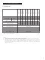
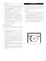
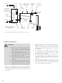
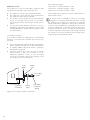
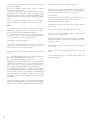
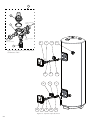
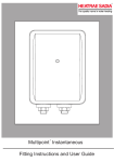
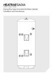
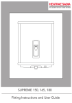
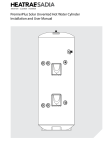
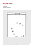
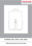
PremierPlus Unvented Hot Water Cylinder Installation and User Manual Contents 1. Introduction.......................................................................................................... 3 1.1 General............................................................................................................ 3 1.2 Symbols used.................................................................................................. 3 1.3 Abbreviations.................................................................................................. 3 1.4 Liabilities.......................................................................................................... 3 2. Safety.................................................................................................................... 4 2.1 General safety warnings................................................................................. 4 2.2 Recommendations.......................................................................................... 4 2.3 Specific safety instructions............................................................................. 4 3. Technical specifications....................................................................................... 5 3.1 Technical data................................................................................................. 5 3.2 Dimensions and connections......................................................................... 7 3.3 Electrical diagram(s)........................................................................................ 8 4. Description of the product............................................................................... 10 4.1 General description...................................................................................... 10 4.2 Operation principle...................................................................................... 10 4.3 Main components......................................................................................... 10 4.4 Standard delivery.......................................................................................... 10 5. Before installation.............................................................................................. 10 5.1 Installation regulations................................................................................. 10 5.2 Installation requirements.............................................................................. 10 5.3 Choice of location......................................................................................... 11 6. Installation.......................................................................................................... 11 6.1 General.......................................................................................................... 11 6.2 Water connections........................................................................................ 12 6.3 Electrical connections................................................................................... 18 6.4 Filling the installation................................................................................... 18 7. Commissioning.................................................................................................. 19 7.1 General.......................................................................................................... 19 7.2 Checklist before commissioning................................................................. 19 7.3 Commissioning procedure........................................................................... 19 8. Operation........................................................................................................... 20 8.1 General.......................................................................................................... 20 9. Maintenance...................................................................................................... 21 9.1 General.......................................................................................................... 21 9.2 Standard inspection & maintenance operations........................................ 21 10. Troubleshooting............................................................................................... 22 10.1 Fault finding................................................................................................ 22 11. Decommissioning............................................................................................ 23 11.1 Decommissioning procedure.................................................................... 23 12.1 Spare parts list............................................................................................... 23 Benchmark checklist.............................................................................................. 25 Commissioning & service records........................................................................ 26 Warranty................................................................................................................. 27 THE BENCHMARK SCHEME Benchmark places responsibilities on both manufacturers and installers. The purpose is to ensure that customers are provided with the correct equipment for their needs, that it is installed, commissioned and serviced in accordance with the manufacturer’s instructions by competent persons and that it meets the requirements of the appropriate Building Regulations and relevant electrical qualifications. The Benchmark Checklist can be used to demonstrate compliance with Building Regulations and should be provided to the customer for future reference. Installers are required to carry out installation, commissioning and servicing work in accordance with the Benchmark Code of Practice which is available from the Heating and Hotwater Industry Council who manage and promote the Scheme. Visit www.centralheating.co.uk 2 for more information. 1. Introduction 1.1 General In the interest of UK customers, we are continuously endeavouring to make improvements in product quality. All the specifications stated in this document are therefore subject to change without notice. The following instructions are offered as a guide to the user and installer. Our liability as the manufacturer may not be invoked in the following cases: The installation must be carried out by a competent plumbing and electrical installer in accordance with Building Regulation G3 (England and Wales), Technical Standard P3 (Scotland) or Building Regulation P5 (Northern Ireland) and the Water Fitting Regulations (England and Wales) or Water Byelaws (Scotland). `` 1.2 Symbols used In these instructions, various risk levels are employed to draw the user’s attention to particular information. In doing so we wish to safeguard the user, avoid hazards and guarantee the correct operation of the appliance. `` `` Installer's liability The installer is responsible for the installation and the commissioning of the appliance. The installer must respect the following instructions: `` DANGER `` Risk of a dangerous situation causing serious physical injury. `` WARNING Risk of dangerous situation causing slight physical injury. Failure to abide by the instructions on using the appliance. Faulty or insufficient maintenance of the appliance. Failure to abide by the instructions on installing the product. `` `` `` `` Read and follow the instructions given in the manuals provided with the appliance. Carry out installation in compliance with the prevailing legislation and standards. Perform the initial start up and carry out any checks necessary. Complete the commissioning checklist. Explain the installation to the user. If maintenance is necessary, warn the user of the obligation to check the appliance and maintain it in good working order. Give all the instruction manuals to the user. Users liability CAUTION Risk of material damage. To guarantee optimum operation of the appliance, the user must respect the following instructions: `` Signals important information. 1.3 Abbreviations `` T&P - Temperature & Pressure relief valve `` PRV - Pressure Reducing Valve `` Prv - Pressure relief valve 1.4 Liabilities Manufacturers liability Our products are manufactured in compliance with the requirements of the various applicable European Directives. This appliance complies with the requirements of the CE marking directive. `` `` `` `` Read and follow the instructions given in the manuals provided with the appliance. Call on qualified professionals to carry out installation and initial start up. Get your installer to explain your installation to you. Have your required checks and services done. Keep the instruction manuals in good condition and close to the appliance. This appliance can be used by children aged from 8 years and above and persons with reduced physical sensory or mental capabilities or lack of experience and knowledge if they have been given supervision or instruction concerning use of the appliance in a safe way and understand the hazards involved. Children shall not play with the appliance. Cleaning and user maintenance shall not be made by children without supervision. Children must be supervised to ensure they do not play with the appliance. 3 2. Safety 2.1 General safety warnings DANGER 2.3 Specific safety instructions WARNING `` This cylinder is unvented and as such becomes pressurised when in operation. The combination of pressurisation and hot water could lead to serious physical injury if the safety instructions in this manual are not adhered to. `` WARNING `` `` `` `` `` If water discharges from the temperature/pressure relief valve on the cylinder shut down the boiler/ immersion heaters. Do not turn off any water supply. Contact a competent installer for unvented water heaters to check the system. Do not tamper with any of the safety valves fitted to the system. If a fault is suspected contact a competent installer. DO NOT bypass the thermal cut-out(s) in any circumstances. Only competent persons having received adequate training are permitted to work on the appliance and the installation. Do not tamper with any of the safety valves or controls supplied with the cylinder. Before any work, switch off the mains supply to the appliance and the mains water supply. Do not switch on if there is a possibility that the water in the cylinder is frozen. CAUTION Do not operate immersion heaters until the cylinder has been filled with water. 2.2 Recommendations WARNING When handling the unit, take appropriate precautions for the weight of the unit. Weights can be found in section 3, table 1 & 2, page 5 & 6. CAUTION Annual maintenance is recommended by a competent person. The HWA Charter Statement requires that all members adhere to the following: `` To supply fit for purpose products clearly and honestly described. `` To supply products that meet, or exceed appropriate standards and building and water regulations. `` To provide pre and post sales technical support. `` To provide clear and concise warranty details to customers. 4 3. Technical specifications 100 indirect 120 indirect 150 indirect 170 indirect 210 indirect 250 indirect 250 indirect 300 indirect 300 indirect 3.1 Technical data: Max direct kW rating @240v 3 3 3 3 3 3 6 3 6 Coil surface area m2 0.58 0.58 0.72 0.79 0.79 0.79 0.79 0.79 0.79 Coil rating (kW) 15l/min 15.2 15.4 15.9 17.3 19.2 18.6 18.6 18.8 18.8 Indirect heat time (mins) 15l/min 24 24 29 30 34 42 42 49 49 Heat loss (kWh in 24h) / Day 1.14 1.25 1.45 1.63 1.91 2.22 2.22 2.52 2.52 Weight full (kg) Weight empty (kg) 125 147 184 203 251 300 300 360 360 25 27 31 33 41 50 50 60 60 Max supply pressure 1.6MPa (16 bar) Max design pressure 0.8MPa (8 bar) Max operating pressure (PRV) 0.35MPa (3.5 bar) Expansion relief valve setting 0.6MPa (6 bar) T&P valve setting 1.0MPa (10 bar)/90°C Maximum primary pressure 1.0MPa (10 bar) Presure drop across coil 0.02MPa (0.2bar) Table 1: Technical data - Indirect Notes: 1. Indirect cylinders tested in accordance with BS EN 12897:2006. 2. Heat up time from cold through 45°C, based on a flow temperature of 80°C +/- 2°C & normal volume. 3. Although the primary coil pressure rating is 1.0MPa (10bar) the 2 port zone valve and coil compression nuts supplied with the cylinder is only rated 0.86MPa (0.86 bar). If the cylinder is to be plumbed into a system delivering 1.0MPa (10 bar) a suitable 2 port zone valve and the coil compression nuts supplied will have to be sourced. 5 100 direct 120 direct 150 direct 170 direct 210 direct 250 direct 250 direct 300 direct 300 direct Max direct kW rating @240v 3 3 3 3 3 3 9 3 9 Direct heat time (based on max kW rating in mins) 99 121 152 173 215 257 88 310 105 Heat loss (kWh in 24h) 1.14 1.25 1.45 1.63 1.91 2.22 2.22 2.52 2.52 Weight full (kg) 123 145 178 199 246 295 295 355 355 Weight empty (kg) 23 25 28 29 36 45 45 55 55 Max supply pressure 1.6MPa (16 bar) Max design pressure 0.8MPa (8 bar) Max operating pressure (PRV) 0.35MPa (3.5 bar) Max expansion vessel charge pressure 0.35MPa (3.5bar) Expansion relief valve setting 0.6MPa (6 bar) T&P valve setting 1.0MPa (10 bar)/90°C Table 2: Technical data - Direct Notes: 1. Direct cylinders tested in accordance with EN 50440 for efficiency parameters 2. Heat up time from cold through 45°C, based on a flow temperature of 80°C +/- 2°C & normal volume. 6 3.2 Dimensions and connections Figure 1: General dimensions - Direct Item B C D 100E 306 493 784 120E 306 616 906 150E 306 800 1090 170E 306 925 1216 210E 306 1184 1474 250E 306 1437 1726 300E 306 1751 2040 Table 3: General dimensions table - Direct Item 100B 120B A 315 315 B 354 354 C 500 616 D 784 906 150B 315 354 800 1090 170B 315 354 927 1216 210B 315 354 1184 1474 250B 315 354 1439 1726 300B 315 354 1754 2040 Table 4: General dimensions table - Indirect 7 3.3 Electrical diagram(s) Terminal block 2 1 3 3 Zone valve (HTG) Room stat Zone valve (DHW) (supplied) G Br Bl 0 GY 1 3 2 G Br Bl 0 2 1 1 2 3 L 2 1 (Supply) N 1 2 3 4 5 6 7 8 9 10 1 2 3 4 5 6 7 8 9 10 2 3 L N HTG ON 2 L 3 L N DHW ON Programmer Junction box 2 N Boiler 3 Pump NOTES: Control terminal numbering may differ from those shown. Refer to instructions with controls selected. A double pole isolating switch must be installed in the mains supply. All earth connections must be connected back to the mains earth supply. Figure 2: Schematic wiring diagram - basic 2 x 2 port valve system Terminal block 2 1 3 3 Zone valve (DHW) (supplied) Zone valve (HTG) G Br Bl 0 G W Bl 0 GY 2 3 L 1 2 L N (Supply) N 1 2 3 4 5 6 7 8 9 10 1 2 3 4 5 6 7 8 9 10 3 HTG ON Programmer DHW ON DHW OFF 1 3 2 2 2 L N Room stat Boiler Figure 3: Schematic wiring diagram - 3 port mid position system Junction box L 3 NOTES: Control terminal numbering may differ from those shown. Refer to instructions with controls selected. A double pole isolating switch must be installed in the mains supply. All earth connections must be connected back to the mains earth supply. 8 2 1 2 N 3 Pump Control Housing Details Element Connections 1 2 3 L N Indirect control wiring 1.5mm² 3 Core HOFR sheathed cable Figure 4: Indirect wiring schematic N L 1.5mm² 3 Core HOFR sheathed cable Figure 5: Direct wiring schematic 9 4. Description of the product 4.1 General description 5. Before installation 5.1 Installation regulations This product is a purpose designed unvented water heater. The unit has a stainless steel inner vessel, which ensures an excellent standard of corrosion resistance. The outer casing is a combination of resilient thermoplastic mouldings and pre-coated steel. All products are insulated with CFC free polyurethane foam to give good heat loss protection. WARNING Installation of the appliance must be carried out by a qualified engineer in accordance with prevailing and national regulations as listed below. `` `` `` The unit is supplied complete with all the necessary safety and control devices needed to allow connection to the cold water mains. All these components are preset and should not be tampered with. `` `` 4.2 Operation principle The unvented cylinder is used to heat and store hot water for use in domestic intallations. Depending on the model the water can be heated directly using Immersion heater(s) or indirectly through a coil in the unit using an indirect heat source. 4.3 Main connections See Figures 7 : Main Schematic on page 13 5.2 Installation requirements Water supply In an unvented system the pressure and flowrate is directly related to the incoming water supply. For this reason it is recommended that the maximum water demand is assessed and the water supply checked to ensure this demand can be satisfactorily met. `` 4.4 Standard delivery The delivery includes: `` `` `` `` `` Cylinder Factory fitted immersion heater(s) and thermal controls Factory fitted Temperature and Pressure Relief Valve (set at 90ºC / 1 Mpa (10bar)) Factory fitted indirect thermostat and thermal cutout Literature pack Instructions (inc benchmark commissioning checklist & service record) `` Cold water control pack Combination valve (inc pressure reducing valve, pressure relief valve and check valve) Expansion vessel and mounting bracket Tundish Nuts & Olives `` `` `` `` `` We suggest the minimum supply requirements should be 0.15MPa (1.5 bar) pressure and 20 litres per minute flow rate. However, at these values outlet flow rates may be poor if several outlets are used simultaneously. A 22mm cold water supply is recommended, however, if a smaller supply exists, which provides sufficient flow, this may be used (although more flow noise may be experienced). The higher the available pressure and flow rate the better the system performance. See table 1 & 3 on pages 5 & 6 for cylinder operating pressures. This is controlled by the cold water combination valve assembly. The water supply must be of wholesome water quality (Fluid Category 1 as defined by the Water Supply Regulations 1999). Outlet/terminal fittings (taps, etc.) `` `` 2 port zone valve (indirect only) `` `` 10 Building Regulations G3 The Building Standards (Scotland) The Building Regulations (Northern Ireland) I.E.E Electrical Regs UK Water Regulations The cylinder can be used with most types of terminal fittings. Outlets situated higher than the cylinder will give outlet pressures lower than that at the heater, a 10m height difference will result in a 1 bar pressure reduction at the outlet. All fittings, pipework and connections must have a rated pressure of at least 6 bar (dependant on cylinder being fitted) at 80°C. It is advantageous in many mixer showers to have a balanced hot and cold water supply, in these instantaces a balanced cold water connection should be placed between the cold water combination valve and the cylinder. Limitations The cylinder should not be used in association with any of the following: `` Solid fuel boilers or any other boiler in which the energy input is not under effective thermostatic control, unless additional and appropriate safety measures are installed. `` Ascending spray type bidets or any other class 1 back syphonage risk requiring that a type A air gap be employed. `` Steam heating plants unless additional and appropriate safety devices are installed. `` Situations where maintenance is likely to be neglected or safety devices tampered with. `` Water supplies that have either inadequate pressure or where the supply may be intermittent. `` Situations where it is not possible to safely pipe away any discharge from the safety valves. `` In areas where the water consistently contains a high proportion of solids, e.g. suspended matter that could block the strainer, unless adequate filtration can be ensured. `` In areas where the water supply contains chloride levels that exceed 250mg/l. 6. Installation 6.1 General After reading the previous sections in this booklet and choosing a good location for the unit please install, paying attention to the following hydraulic, electrical and commissioning sections. Boiler selection `` `` `` `` The boiler should have a control thermostat and non self-resetting thermal cut-out and be compatible with unvented storage water heaters. Can be a sealed system or open vented type maximum primary pressure 3 bar. The primary flow from the boiler must be pumped. Gravity circulation will not work due to the special design of the primary heat exchanger. It is recomended that an air bleed point or automatic air vent is incorporated in the primary return pipework close to the unvented system. The boiler cannot be vented through the cylinder. 5.3 Choice of location The cylinder must be vertically floor mounted. Although location is not critical, the following points should be considered: `` `` `` `` `` `` The cylinder should be sited to ensure minimum dead leg distances, particularly to the point of most frequent use. Avoid siting where extreme cold temperatures will be experienced. All exposed pipe work should be insulated. The discharge pipework from the safety valves must have minimum fall of 1:200 from the unit and terminate in a safe and visible position. Access to associated controls and immersion heaters must be available for the servicing and maintenance of the system. Where these controls are installed against a wall a minimum distance of 250mm must be left. Ensure that the floor area for the cylinder is level and capable of permanently supporting the weight when full of water (see table 1 & 3, page 5 & 6 for weights). Prior to installation the unit should be stored and transported in an area free from excessive damp or humidity. The Unit should be stored in a frost free environment. WALL Min 250mm Min 250mm Figure 6: Acess schematic (not to scale) 11 To hot outlets T&P relief valve Expansion vessel Balanced cold water connection (if required) Cold water combination valve Boost element/ control housing (PP120E to PP300E models only) Isolating valve (not supplied) Mains water supply Element/ controls housing Secondary return (if required) use swept tee Primary return Primary flow NOTE: Primary heating coil fitted on PP100B to PP300B models only Inlet Drain cock (not supplied) Tundish Discharge pipe Figure 7: Typical installation schematic (not to scale) 6.2 Water connections WARNING `` `` `` `` `` Under no circumstances should the factory fitted temperature/pressure relief valve be removed other than by a competent person. To do so will invalidate any guarantee or claim. The cold water combination valve assembly must be fitted on the mains water supply to the cylinder. No control or safety valves should be tampered with or used for any other purpose. The discharge pipe should not be blocked or used for any other purpose. The tundish should not be located adjacent to any electrical components. Refer to the installation schematic (fig 7 above) for details on the pipework layout. Specific details for the discharge pipework layout is also provided in figure 10 on page 18 12 `` `` `` `` All pipe fittings are made via 22mm compression fittings directly to the unit (nuts and olives supplied). The fittings are also threaded 3/4" BSP male parallel should threaded pipes connections be required. A stopcock or servicing valve should be incorporated into the cold water supply to enable the cylinder to be isolated from the mains supply for maintenance or servicing.. A suitable draining tap should be installed in the cold water supply to the cylinder between the expansion valve and the heater at as low a level as possible. It is recommended that the outlet point of the drain pipework be at least 1 metre below the level of the heater (this can be achieved by attaching a hose to the drain tap outlet spigot) Cold water control pack CAUTION `` Flush supply pipework before connection to remove all flux and debris prior to fitting the inlet controls. Failure to do this may result in irreparable damage to the controls and will invalidate any warranty. `` Primary circuit control `` `` `` `` `` `` `` The cold water combination valve can be connected anywhere on the cold water cylinder supply prior to the expansion vessel. No other valves should be placed between the cold water combination valve and the cylinder. The cold water combination valve is installed as a complete one-piece unit, the valve incorporates the pressure reducer, strainer, expansion valve and check valve. The pressure setting is set to 3.5 bar. The valve can be fitted in any orientation to suit the installation as long as the valve is installed with the direction of flow arrows pointing in the correct direction. The expansion relief valve should be installed with Expansion valve Cold mains connection (22mm) the discharge pipework in either the horizontal position or facing downwards. Where discharge pipework is difficult to attain, the local building control officer from the local council should be sought for advice as this falls under G3 guidelines and is not down to the manufacturer of unvented systems `` `` `` The 2 port motorised valve supplied with the cylinder MUST be fitted on the primary flow to the cylinder heat exchanger and wired such that in the event of the cylinder overheating it will close the primary circuit. Primary circulation to the cylinder heat exchanger must be pumped; gravity circulation WILL NOT WORK. It is recommended that an air bleed or automatic air vent is incorporated in the primary return pipe work close to the unit. Boiler flow temperature should be set to 82° (maximum flow temperature to primary heat exchanger 88°C). Expansion valve outlet (15mm) Direction of flow Outlet connection (22mm) Pressure reducing valve cartridge (3.5bar) Figure 8: 3 bar pressure reducing valve 13 Expansion vessel The expansion vessel accommodates expansion that results from heating the water inside the unit. Pipe capacity (copper): 15mm O.D. = 0.13 l/m (10 litres = 77m) 22mm O.D. = 0.38 l/m (10 litres = 26m) 28mm O.D. = 0.55 l/m (10 litres = 18m) `` `` Note: Plastic pipe capacities may be reduced due to thicker wall sections. `` `` The expansion vessel is pre-charged at 3.5bar. The expansion vessel must be connected between the expansion valve and the cylinder. The location of the expansion vessel should allow access to recharge the pressure as and when necessary, this can be done using a normal car foot pump. It is recommended that the expansion vessel is adequately supported. An expansion vessel wall mounting bracket is supplied for this purpose and should be fitted. Secondary circulation If secondary circulation is required it is recommended that it be connected to the cylinder as shown (see fig. 9, below). `` `` `` The secondary return pipe should be in 15mm pipe and incorporate a check valve to prevent backflow. A suitable WRAS approved bronze circulation pump will be required. On large systems, due to the increase in system water content, it may be necessary to fit an additional expansion vessel to the secondary circuit. This should be done if the capacity of the secondary circuit exceeds 10 litres. Cold supply Swept tee Secondary return Cold inlet connection Check valve Secondary circulation pump Figure 9: Secondary circulation schematic 14 In direct electric installations where a secondary circulation is required particular attention should be paid by the installer to maintain the returning water temperature (guidelines state that a minimum of 55°C return temperature is advisable). Factors such as, but not limited to, secondary circulation flow rates, minimising heat loss of all secondary circuit pipework and timed operation during periods of high demand are critical to the correct operation and longevity of the heating element(s) and thermostats. Discharge It is a requirement of Building Regulation G3 that any discharge from an unvented system is conveyed to where it is visible, but will not cause danger to persons in or about the building. The tundish and discharge pipes should be fitted in accordance with the requirements and guidance notes of Building Regulation G3. The G3 Requirements and Guidance section 3.50 - 3.63 are reproduced in the following sections of this manual. For discharge pipe arrangements not covered by G3 Guidance advice should be sought from your local Building Control Officer. Any discharge pipe connected to the pressure relief devices (expansion valve and temperature/pressure relief valve) must be installed in a continuously downward direction and in a frost free environment. Water may drip from the discharge pipe of the pressure relief device. This pipe must be left open to the atmosphere. The pressure relief device is to be operated regularly to remove lime deposits and to verify that it is not blocked. G3 REQUIREMENT “...there shall be precautions...to ensure that the hot water discharged from safety devices is safely conveyed to where it is visible but will not cause danger to persons in or about the building.” The following extract is taken from the latest G3 Regulations Discharge pipes from safety devices Discharge pipe D1 3.50 Each of the temperature relief valves or combined temperature and pressure relief valves specified in 3.13 or 3.17 should discharge either directly or by way of a manifold via a short length of metal pipe (D1) to a tundish. 3.51The diameter of discharge pipe (D1) should be not less than the nominal outlet size of the temperature relief valve. 3.52Where a manifold is used it should be sized to accept and discharge the total discharge from the discharge pipes connected to it. 3.53Where valves other than the temperature and pressure relief valve from a single unvented hot water system discharge by way of the same manifold that is used by the safety devices, the manifold should be factory fitted as part of the hot water storage system unit or package. Tundish 3.54The tundish should be vertical, located in the same space as the unvented hot water storage system and be fitted as close as possible to, and lower than, the valve, with no more than 600mm of pipe between the valve outlet and the tundish (see fig 10). Note: To comply with the Water Supply (Water Fittings) Regulations, the tundish should incorporate a suitable air gap. 3.55Any discharge should be visible at the tundish. In addition, where discharges from safety devices may not be apparent, e.g. in dwellings occupied by people with impaired vision or mobility, consideration should be given to the installation of a suitable safety device to warn when discharge takes place, e.g. electronically operated. Discharge pipe D2 3.56 The discharge pipe (D2) from the tundish should: (a) have a vertical section of pipe at least 300mm long below the tundish before any elbows or bends in the pipework (see fig. 10); and (b) be installed with a continuous fall thereafter of at least 1 in 200. 3.57 The discharge pipe (D2) should be made of: (a) metal; or (b) other material that has been demonstrated to be capable of safely withstanding temperatures of the water discharged and is clearly and permanently marked to identify the product and performance standard (e.g. as specified in the relevant part of BS 7291). 3.58The discharge pipe (D2) should be at least one pipe size larger than the nominal outlet size of the safety device unless its total equivalent hydraulic resistance exceeds that of a straight pipe 9m long, i.e. for discharge pipes between 9m and 18m the equivalent resistance length should be at least two sizes larger than the nominal outlet size of the safety device; between 18 and 27m at least 3 sizes larger, and so on; bends must be taken into account in calculating the flow resistance. See Fig 10, Table 5 and the worked example. Note: An alternative approach for sizing discharge pipes would be to follow Annex D, section D.2 of BS 6700:2006 Specification for design, installation, testing and maintenance of services supplying water for domestic use within buildings and their curtilages. 3.59Where a single common discharge pipe serves more than one system, it should be at least one pipe size larger than the largest individual discharge pipe (D2) to be connected. 3.60 The discharge pipe should not be connected to a soil discharge stack unless it can be demonstrated that the soil discharge stack is capable of safely withstanding temperatures of the water discharged, in which case, it should: (a) contain a mechanical seal, not incorporating a water trap, which allows water into the branch pipe 15 without allowing foul air from the drain to be ventilated through the tundish; (b) be a separate branch pipe with no sanitary appliances connected to it; (c) if plastic pipes are used as branch pipes carrying discharge from a safety device they should be either polybutylene (PB) to Class S of BS 7291-2:2006 or cross linked polyethylene (PE-X) to Class S of BS 7291-3:2006; and (d) be continuously marked with a warning that no sanitary appliances should be connected to the pipe. Note: 1. Plastic pipes should be joined and assembled with fittings appropriate to the circumstances in which they are used as set out in BS EN ISO 1043-1. 2. Where pipes cannot be connected to the stack it may be possible to route a dedicated pipe alongside or in close proximity to the discharge stack. Termination of discharge pipe 3.61The discharge pipe (D2) from the tundish should terminate in a safe place where there is no risk to persons in the vicinity of the discharge. 3.62Examples of acceptable discharge arrangements are: (a) to a trapped gully with the end of the pipe below a fixed grating and above the water seal; (b) downward discharges at low level; i.e. up to 100mm above external surfaces such as car parks, hard standings, grassed areas etc. are acceptable providing that a wire cage or similar guard is positioned to prevent contact, whilst maintaining visibility; and (c) discharges at high level: e.g. into a metal hopper and metal downpipe with the end of the discharge pipe clearly visible or onto a roof capable of withstanding high temperature discharges of water and 3m from any plastic guttering system that would collect such discharges. 3.63The discharge would consist of high temperature water and steam. Asphalt, roofing felt and non-metallic rainwater goods may be damaged by such discharges. 16 Worked example of discharge pipe sizing Fig. 10: shows a G1/2 temperature relief valve with a discharge pipe (D2) having 4 No. elbows and length of 7m from the tundish to the point of discharge. From Table 5: Maximum resistance allowed for a straight length of 22mm copper discharge pipe (D2) from a G1/2 temperature relief valve is 9.0m. Subtract the resistance for 4 No. 22mm elbows at 0.8m each = 3.2m Therefore the permitted length equates to: 5.8m 5.8m is less than the actual length of 7m therefore calculate the next largest size. Maximum resistance allowed for a straight length of 28mm pipe (D2) from a G1/2 temperature relief valves equates to 18m. Subtract the resistance of 4 No. 28mm elbows at 1.0m each = 4.0m Therefore the maximum permitted length equates to: 14m As the actual length is 7m, a 28mm (D2) copper pipe will be satisfactory. Valve Outlet Size Minimum Size Of Discharge Pipe D1 Minimum Size Of Discharge Pipe D2 From Tundish Maximum Resistance Allowed, Expressed As A Length Of Straight Pipe (I.E. No Elbows Or Bends) Resistance Created By Each Elbow Or Bend G1/2 15mm 22mm 28mm 35mm up to 9m up to 18m up to 27m 0.8m 1.0m 1.4m G3/4 22mm 28mm 35mm 42mm up to 9m up to 18m up to 27m 1.0m 1.4m 1.7m G1 28mm 35mm 42mm 54mm up to 9m up to 18m up to 27m 1.4m 1.7m 2.3m Table 5: Sizing of copper discharge pipe (D2) for common temperature relief valve outlet sizes Safety device (e.g. Temperature relief valve) Metal discharge pipe (D1) from Temperature relief valve to tundish Tundish 600mm maximum 300mm minimum Discharge below fixed grating (Building Regulation G3 section 3.61 gives alternative points of discharge) Fixed grating Discharge pipe (D2) from tundish, with continuous fall. See Building Regulation G3 section 3.56, Table 5 and worked example Trapped gully Figure 10: Typical discharge pipe arrangement (extract from Building Regulation G3 Guidance Section 3.50) 17 6.3 Electrical connections In case of difficulty contact service support; contact details are available on page 26 of this booklet. WARNING `` `` `` `` `` `` Disconnect from the mains electrical supply before removing any covers. Never attempt to replace the immersion heater(s) other than with genuine manufacturers components. Using other manufacturers components may invalidate the warranty on the cylinder. DO NOT bypass the thermal cut-out(s) in any circumstances. All electrical wiring should be carried out by a competent electrician and be in accordance with the latest I.E.E Wiring Regulations. Each circuit must be protected by a suitable fuse and double pole isolating switch with a contact separation of at least 3mm in both poles. DO NOT operate the immersion heaters until the cylinder has been filled with water. The immersion heater(s) should be wired in accordance with fig 4 & 5, page 10. Space and heating systems controls `` `` 18 The controls provided with the cylinder will ensure the safe operation of the unit within the central heating system. Other controls will be necessary to control the space heating requirements and times that the system is required to function. The cylinder is compatible with most heating controls, examples of electrical circuits are shown in figs. 2 and 3, page 9. However, other systems may be suitable, refer to the controls manufacturers instructions, supplied with the controls selected, for alternative system wiring schemes. 6.4 Filling the installation `` `` `` `` `` `` Check expansion vessel pre-charge pressure. The vessel is supplied precharged to 3.5 bar to match the control pressure of the pressure reducing valve. The precharge pressure is checked using using a car tyre gauge by unscrewing the plastic cap opposite the water connection. Check all connections for tightness including the immersion heater(s). An immersion heater key spanner is supplied for this purpose. Ensure the drain cock is CLOSED. Open a hot tap furthest from the cylinder. Open the mains stop cock to fill the unit. When water discharges from the tap, alow to run for a few minutes to throughly flush through any residue, dirt or swarf, then close the tap. Open successive hot taps to purge the system of air. `` 7. Commissioning 7.1 General After filling the installation with water in the previous section please follow the following steps to complete the installation of the unit. WARNING `` Indirect units DO NOT operate the immersion heaters or primary circuit until the cylinder has been filled with water. `` `` 7.2 Checklist before commissioning `` `` `` `` `` `` If necessary the temperature can be adjusted by inserting a flat bladed screwdriver in the adjustment spindle on front of the immersion heater thermostat and rotating. The adjustment represents a temperature range of 12°C to 72°C. Check the operation of thermostat(s) and that no water has discharged from the expansion relief valve or temperature/pressure relief valve during the heating cycle. Check all water connections for leaks and rectify as necessary. Turn off mains water supply. Remove the pressure reducing valve head work to access the strainer mesh, clean and re-fit. Turn the water supply back on. Manually open, for a few seconds, each relief valve in turn, checking that water is discharged and runs freely through the tundish and out at the discharge point. Ensure that the valve(s) reseat satisfactorily. `` `` Fill the indirect (primary) circuit following the boiler manufacturer’s commissioning instructions. To ensure the cylinder primary heat exchanger is filled, the 2 port motorised valve (supplied) should be manually opened by moving the lever on the motor housing to the MANUAL setting. When the primary circuit is full return the lever to the AUTOMATIC position. Switch on the boiler, ensure the programmer is set to Hot Water and allow the cylinder to heat up to a normal working temperature (60 - 65oC recommended). If necessary the temperature can be adjusted by inserting a flat bladded screwdriver in the adjustment knob and rotating. The minimum thermostst setting is 10°C. The maximum thermostat setting is 72°C. WARNING 7.3 Commissioning procedure `` Direct units `` Switch on electrical supply to the immersion heater(s) and allow the cylinder to heat up to normal working temperature (60 - 65°C recommended). `` If the unit is to be left unused following installation and commissioning e.g. unocupied properties, the water heater should be drained or regularly flushed through with fresh mains water once a week. When placing the unit into service, the procedure for filling the unit and the system checks above should be observed. THERMAL CUT-OUT RESET BUTTON SPINDLE POSITIONS = MINIMUM TEMP = MAXIMUM TEMP = APPROX 60 °C ROTATE SPINDLE CLOCKWISE FOR TEMPERATURE INCREASE AND COUNTER CLOCKWISE FOR TEMPERATURE DECREASE TEMPERATURE ADJUSTING SPINDLE Figure 11: Direct controls 19 8. Operation `` 8.1 General WARNING `` `` `` If water discharges from the temperature/pressure relief valve on the cylinder shut down the heat source. Do not turn off any water supply. Contact a competent installer for unvented water heaters to check the system. Do not tamper with any of the safety valves fitted to the system. If a fault is suspected contact a competent installer. DO NOT bypass the thermal cut-out(s) in any circumstances. `` `` `` All immersion heaters are fitted with a combined thermostat and thermal cut-out located under the terminal cover mounted on the side of the product. Access to the thermostat can be made by opening the immersion heater cover - DISCONNECT THE ELECTRICAL SUPPLY BEFORE OPENING THE COVER(S). Temperature adjustment is made by inserting a flat bladed screwdriver in the slot on the adjustment disc on top of the thermostat and rotating. The adjustment represents a temperature range of 12°C to 72°C. Figure 11, page 20. Maximum working temperature is 72°C/154°F. In very hard water areas limit to 60/65°C (140/150°F). DO NOT bypass the thermal cut-out(s) in any circumstances. Benchmark Temperature controls - indirect units The cylinder is covered by the Benchmark Scheme which aims to improve the standards of installation and commissioning of domestic heating and hot water systems in the UK and to encourage regular servicing to optimise safety, efficiency and performance. `` Benchmark is managed and promoted by the Heating and Hotwater Industry Council. For more information visit www.centralheating.co.uk. `` Please ensure that the installer has fully completed the Benchmark Checklist (page 26) of this manual and that you have signed it to say that you have received a full and clear explanation of its operation. The installer is legally required to complete a commissioning checklist as a means of complying with the appropriate Building Regulations (England & Wales). `` All installations must be notified to Local Area Building Control either directly or through a Competent Persons Scheme. A Building Regulations Compliance Certificate will then be issued to the customer who should, on receipt, write the Notification Number on the Benchmark Checklist. This product should be serviced regularly to optimise its safety, efficiency and performance. The service engineer should complete the relevant Service Record on the Benchmark Checklist after each service. The Benchmark Checklist may be required in the event of any warranty work. Flow performance When initially opening hot outlets a small surge in flow may be noticed as pressures stabilise. This is quite normal with unvented systems. In some areas cloudiness may be noticed in the hot water. This is due to aeration of the water, is quite normal and will quickly clear. 20 Temperature controls – direct units immersion heater(s) `` The cylinder units are fitted with an indirect thermostat and thermal cut-out. These controls must be wired in series with the 2 port motorised zone valve supplied to interrupt the flow of primary water around the heat exchanger coil when the control temperature has been reached. The controls are located within the lower terminal housing along with the immersion heater thermostat. The thermostat is factory set to give a water storage temperature of approx 55°C to 60°C. Access to the thermostat can be made by opening the terminal housing cover. DISCONNECT THE ELECTRICAL SUPPLY BEFORE OPENING THE COVER. Temperature adjustment is made by inserting a flat bladded screwdriver in the adjustment knob and rotating. The minimum thermostst setting is 12°C, The maximum thermostat setting is 72°C. DO NOT bypass the thermal cut-out(s) in any circumstances. Operational faults Operational faults and their possible causes are detailed in the Fault Finding section (p.23) of this book. It is recommended that faults should be checked by a competent installer. The air volume within the expansion vessel will periodically require recharging to ensure expanded water is accommodated within the system. A discharge of water INTERMITTENTLY from the expansion valve will indicate the air volume has reduced to a point where it can no longer accommodate the expansion. This will require a suitably qualified person to check the expansion vessel pressure and no attempt should be made to re-pressurize the expansion vessel by the end user. 9. Maintenance 9.1 General `` `` `` Maintenance requirements Unvented hot water systems have a continuing maintenance requirement in order to ensure safe working and optimum performance. It is essential that the relief valve(s) are periodically inspected and manually opened to ensure no blockage has occurred in the valves or discharge pipework. Maintenance of this appliance should only be carried out by a suitably qualified person. Failure to do so could invalidate the warranty. `` `` `` Similarly cleaning of the strainer element and replacement of the air in the expansion vessel will help to prevent possible operational faults. The maintenance checks described below should be performed by a competent person on a regular basis, e.g. annually to coincide with boiler maintenance. `` After any maintenance, please complete the relevant Service Interval Record section of the Benchmark Checklist on page 26 of this document. CAUTION 9.2 Standard inspection & maintenance operations Inspection The immersion heater boss can be used as an access for inspecting the cylinder internally. Safety valve operation CAUTION Water discharged may be very hot! DO NOT use a sharp implement as damage to the element surface could be caused. `` `` `` Manually operate the temperature/pressure relief valve for a few seconds. `` Check water is discharged and that it flows freely through the tundish and discharge pipework. `` Check valve reseats correctly when released. `` Repeat the above procedure for the expansion relief valve. Strainer `` `` `` `` `` `` Turn off the isolating valve prior to the Pressure Reducing Valve or the main stop cock to the system. Open the lowest hot tap in the system to relieve the system pressure. Using a spanner unscrew the pressure reducing cartridge and remove the moulded housing. The strainer will be removed with the cartridge. Wash any particulate matter from the strainer under clean running water. Replace the strainer and screw the Pressure Reducing Valve cartridge into the moulded housing. Close hot tap, turn on isolating valve or main stop cock to the system. Check for leaks. Ensure sealing surfaces are clean and seals are undamaged, if in doubt fit a new gasket. (spare part number 95 611 822) Replace immersion heater(s), making sure not to trap the gasket. Rewire, check, close and secure immersion heater housing cover(s). Re-commissioning `` `` Descaling immersion heater(s) Turn off the mains water supply, isolate the electrical supply and turn off boiler Attach a hosepipe to the drain cock having sufficient length to take water to a suitable discharge point below the level of the unit. Open a hot tap close to the unit and open drain cock to drain unit. If water fails to drain vent the unit manually by opening the temperature and pressure relief valve. Open the cover(s) to the immersion heater housing(s) and disconnect wiring from immersion heater(s). Unscrew the immersion heater backnut(s) and withdraw the immersion heater from the cylinder. A key spanner is supplied with the product for easy removal and tightening of the immersion heater(s). Over time the immersion heater gasket may become stuck to the mating surface. To break the seal insert a round shafted screwdriver into one of the pockets on the immersion heater and gently lever up and down. Take care when lifting the immersion heater out of the cylinder and work within safe working practices. Carefully remove any scale from the surface of the element(s). `` `` `` `` `` `` Check all electrical and plumbing connections are secure. Close the drain cock. With a hot tap open, turn on the cold water supply and allow unit to refill. DO NOT switch on the immersion heater(s) or boiler until the unit is full. When water flows from the hot tap allow to flow for a short while to purge air and flush through any disturbed particles. Close hot tap and then open successive hot taps in system to purge any air. When completely full and purged check system for leaks. The heating source (immersion heater(s) or boiler) can then be switched on Expansion vessel charge pressure `` Remove the dust cap on top of the vessel. Check the charge pressure using a tyre pressure gauge. The pressure (system de-pressured) should be 0.35MPa (3.5 bar). If it is lower than the required setting it should be re-charged using a tyre pump (schrader valve type). DO NOT OVER-CHARGE. Re-check the pressure and when correct replace 21 the dust cap. 10. Troubleshooting `` WARNING Do not tamper with any of the safety valves or controls supplied with the cylinder as this will invalidate any guarantee. 10.1 Fault finding Important `` `` `` `` `` After servicing, complete the relevant Service Interval Record section of the Benchmark Checklist located on pages 25 and 26 of this document. Servicing should only be carried out by competent persons in the installation and maintenance of unvented water heating systems. Any spare parts used MUST be authorised parts. Disconnect the electrical supply before removing any electrical equipment covers. NEVER bypass any thermal controls or operate system without the necessary safety valves. Fault No hot water flow Water from hot tap is cold Water discharges from expansion valve Water discharges from T&P relief valve The fault finding chart (table 6, below) will enable operational faults to be identified and their possible causes rectified. Any work carried out on the unvented water heater and its associated controls MUST be carried out by a competent installer for unvented water heating systems. In case of doubt contact service support. Spare Parts A full range of spare parts are available for the cylinder range (table 7, page 24). Refer to the technical data label on the unit to identify the model installed and ensure the correct part is ordered. You will need to quote the serial number, which is printed on the data label. Possible Cause Remedy Mains water supply off Check and open stop cock Strainer blocked Turn off water supply. Remove strainer and clean Cold water combination valve incorrectly fitted Check and refit as required Direct immersion heater not switched on Check and switch on Direct immersion heater thermal cut-out has operated Check, reset by pushing button on thermostat Indirect programmer set to central heating only Check, set to domestic hot water programme Indirect boiler not working Check boiler operation. If fault is suspected consult boiler manufacturer’s instructions Indirect thermal cut-out has operated Check, reset by pushing button on thermostat. Check operation of indirect thermostat Indirect motorised valve not connected correctly Check wiring and/or plumbing connections to motorised valve Intermittently Expansion vessel charge pressure has reduced below 3.5bar, or set to high See Maintenance section (p.22) for re-charging of expansion vessel procedure Continually Cold water combination valve pressure reducer not working correctly. Expansion valve seat damaged Check pressure from cold water combination valve. If greater than 3.5bar replace pressure reducing valve cartridge. Remove expansion valve cartridge, check condition of seat. If necessary fit new expansion valve Thermal control failure CAUTION: Water will be very hot! Switch off power to immersion heater(s) and shut down boiler. DO NOT turn off water supply. When discharge stops check all thermal controls, replace if faulty Oxygenated water Water from a pressurised system releases oxygen bubbles when flowing. The milkiness will disappear after a short while Milky water Table 6: Fault finding chart 22 Water contained in the cylinder may be very hot, especially following a thermal control failure. Caution must be taken when drawing water from the unit. 11. Decommissioning 11.1 Decommissioning procedure `` `` `` `` `` `` Isolate electrical supplies and make safe Isolate the water supply Drain the cylinder Drain the primary circuit (indirect only) Remove cylinder Cap pipework Environmental information Products are manufactured from many recyclable materials. At the end of their useful life they should be disposed of at a Local Authority Recycling Centre in order to realise the full environmental benefits. Insulation is by means of an approved CFC/HCFC free polyurethane foam with an ozone depletion factor of zero. 12. Spare parts 12.1 Spare parts list A full range of spare parts are available for the cylinder range. Refer to the Technical Data label on the unit to identify the model installed and ensure the correct part is ordered. 1 2 3 4 5 6 7 8 9 10 11 12 13 14 15 16 17 18 19 20 21 DESCRIPTION Immersion heater (lower) Immersion heater (upper) Immersion heater gasket Immersion heater backnut Immersion heater key - not shown Tundish - not shown Expansion valve - 6bar Cold water combination valve complete Cold water combination body Pressure reducing valve cartridge 3.5 bar Temperature/Pressure Relief Valve Expansion vessel 12 litre (100,120 and 150 litre models) - not shown Expansion vessel 18 litre (170 and 210 litre models) - not shown Expansion vessel 24 litre (250 and 300 litre models) - not shown Blanking plate assembly - not shown Nut & olive pack (4 of each) - not shown Direct combined Thermostat and Thermal cut-out Indirect combined Thermostst and Thermal cut-out 6 way terminal block 3 way terminal block 2 port motorised valve (22mm connections) - not shown SPARES NUMBER 95606984 95606986 95611822 95607869 95607861 95605838 95605899 95605897 95605900 95605898 95605810 95607863 95607864 95607612 95605881 95607838 95612717 95612716 95607933 95607932 95605819 Table 7: Spares 23 8 10 Outlet Connection (22mm) 9 Outlet Connection (15mm) Cold Mains Connection (22mm) 4 3 17 11 2 20 7 Figure 12: Exploded view of cold water combination valve 22 18 23 4 17 3 22 1 19 Figure 13: Cylinder exploded view 24 MAINS PRESSURE HOT WATER STORAGE SYSTEM COMMISSIONING CHECKLIST This Commissioning Checklist is to be completed in full by the competent person who commissioned the storage system as a means of demonstrating compliance with the appropriate Building Regulations and then handed to the customer to keep for future reference. Failure to install and commission this equipment to the manufacturer’s instructions may invalidate the warranty but does not affect statutory rights. Customer name: Telephone number: Address: Cylinder Make and Model Cylinder Serial Number Commissioned by (PRINT NAME): Registered Operative ID Number Company name: Telephone number: Company address: Commissioning date: ALL SYSTEMS PRIMARY SETTINGS (indirect heating only) Is the primary circuit a sealed or open vented system? Sealed Open °C ALL SYSTEMS What is the incoming static cold water pressure at the inlet to the system? bar Yes Is the installation in a hard water area (above 200ppm)? No Yes No Yes No What is the hot water thermostat set temperature? °C I/min Yes Type of control system (if applicable) Y Plan Is the cylinder solar (or other renewable) compatible? S Plan Other Yes What is the hot water temperature at the nearest outlet? No °C All appropriate pipes have been insulated up to 1 metre or the point where they become concealed Yes UNVENTED SYSTEMS ONLY What is the pressure reducing valve setting? bar Yes The tundish and discharge pipework have been connected and terminated to Part G of the Building Regulations Has the expansion vessel or internal air space been checked? No Yes Yes No Yes No THERMAL STORES ONLY What store temperature is achievable? °C What is the maximum hot water temperature? °C ALL INSTALLATIONS The hot water system complies with the appropriate Building Regulations Yes The system has been installed and commissioned in accordance with the manufacturer’s instructions Yes The system controls have been demonstrated to and understood by the customer Yes The manufacturer’s literature, including Benchmark Checklist and Service Record, has been explained and left with the customer Yes Commissioning Engineer’s Signature Customer’s Signature * © Heating and Hotwater Industry Council (HHIC) www.centralheating.co.uk 25 SERVICE RECORD It is recommended that your hot water system is serviced regularly and that the appropriate Service Record is completed. Service Provider Before completing the appropriate Service Record below, please ensure you have carried out the service as described in the manufacturer’s instructions. SERVICE 01 SERVICE 02 Engineer name: Company name: Company name: Telephone No: Telephone No: Email Address: Email Address: Comments: Comments: Signature Signature SERVICE 03 Date: SERVICE 04 Engineer name: Engineer name: Company name: Company name: Telephone No: Telephone No: Email Address: Email Address: Comments: Comments: Signature Signature SERVICE 05 Date: SERVICE 06 Engineer name: Engineer name: Company name: Company name: Telephone No: Telephone No: Email Address: Email Address: Comments: Comments: Signature Signature SERVICE 07 Date: SERVICE 08 Engineer name: Engineer name: Company name: Company name: Telephone No: Telephone No: Email Address: Email Address: Comments: Comments: Signature Signature SERVICE 09 26 Date: Engineer name: Date: SERVICE 10 Engineer name: Engineer name: Company name: Company name: Telephone No: Telephone No: Email Address: Email Address: Comments: Comments: Signature Signature Date: Date: Date: Date: Date: Warranty Guarantee Terms and Conditions WARNING: Should the factory fitted temperature and pressure relief valve be tampered with or removed your guarantee will be invalidated. Neither the Distributor nor Manufacturer shall be responsible for any consequential damage howsoever caused. Warranty Terms Heatrae Sadia warranty guarantees the water heater cylinder against faulty manufacture or materials for a period of two years from the date of purchase including parts and labour. This two year warranty is extended to five years for the cold water control valve and to 30 years for the stainless steel inner vesssel. These guarantees are valid provided that: • • • • • • • • • • • • The water heater has been installed by a competent engineer and as per the instructions contained in the installation manual and all relevant Codes of Practice and Regulations in force at the time of installation. Any disinfection has been carried out in accordance with BS EN 806-5:2012 Should the factory fitted temperature and pressure relief valve be tampered with or removed your guarantee will be invalidated. The water heater has not been modified in anyway other than by our approved engineers. The water heater has only been used for the storage of wholesome sanitary water (max 250mg/l chloride). The water heater unit has not been subjected to excessive pressure beyond the guidelines detailed in the installation instructions. The water heater unit has not been subjected to frost, nor has it been tampered with or been subject to misuse or neglect. No factory fitted parts have been removed for un-authorised repair or replacement. The Benchmark™ commisioning checklist service record included in this product guide has been completed. Regular maintenance has been carried out by a competent person in accordance with the requirements set in the maintenance section of the installation manual and any replacement parts used should be approved spare parts. Within 60 days of purchase the owner completes and returns the certificate supplied to register the product. Evidence of purchase and date of supply must be submitted upon making a claim. The guarantee is not valid outside of the United Kingdom. The warranty does NOT cover: Consequential damages or profit loss which may arise from a defect. Warranty claims have no delaying effect on the payment dates and other demands Your water heater warranty covers you for a direct replacement and labour in the event that the unit fails prematurely as a result of a proved manufacturing defect. In order that this can be achieved, full access to replace the unit is essential. If it is found that access can not be achieved the warranty will be limited to the replacement of the unit only and subsequent labour charges would not be met under the warranty. For installations outside of the United Kingdom, please contact either the Heatrae Sadia Export Department on Tel: +44 1603 420271 or Baxi International on Tel: +44 1926 478323 for further details of the guarantee terms and conditions applicable. This guarantee does not affect your statutory rights. 27 Electric Water Heating Co. 2 Horsecroft Place Pinnacles Harlow Essex CM19 5BT Tel: 0845 0553811 E-Mail: [email protected] SPD Special Product Division Units 9 & 10 Hexagon Business Centre Springfield Road Hayes Middlesex UB4 0TY Tel: 020 8606 3567 Parts Center Tel: 0344 292 7057 www.partscenter.co.uk Newey & Eyre Unit 3-5 Wassage Way Hampton Lovett Ind. Estate Droitwich, Worcestershire WR9 0NX Tel: 01905 791500 Fax: 01905 791501 UK Spares Ltd Unit 1155 Aztec West Almondsbury Bristol BS32 4TF Tel: 01454 620500 SPECIFICATION ADVICE HOTLINE t | 01603 420220 e | [email protected] AFTER SALES SERVICE t | 0344 871 1535 e | [email protected] w | heatraesadia.com MADE IN THE UK 30 YEAR WARRANTY 30 OUR NATIONWIDE NETWORK OF CUSTOMER SUPPORT ENGINEERS Heatrae Sadia has its very own dedicated nationwide network of highly trained customer support engineers so you can have peace of mind that we’re always here to help. PRODUCT RANGE Full specification details on all our products are available to download from our website. To support our corporate responsibility and sustainability charters and reduce our printed material we encourage you to download product brochures from our website. In designing these files we have taken into account the need to access data on screen. If you would like to receive a printed copy of our full product catalogue please call our literature hotline on 01603 420127. Heatrae Sadia Heating may introduce modifications to their products from time to time. Consequently, the details given in this brochure are subject to alteration without notice. Alternatively contact your local supplying merchant or wholesale branch or use our online stockist finder at www.interpartspares.co.uk Please follow us online: PN 7032982 Issue 1 © Heatrae Sadia 2015