1
Filière Systèmes industriels
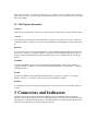
Orientation Infotronics
Diplôme 2007
Antoine Zen-Ruffinen
Soekris based MP
Professeur
François Corthay
Expert
Prof. Jorgen Nordberg
Sion, le 18 février 2008
Acknowledgements
My thanks to:
• Patrik Arlos for the great reception and support he make to me.
• Silvan for been a good travelling companion.
• HES-SO\\Valais and MOVE office to give me the chance to add a little bit adventure
to the writing of this documents.
• The folks that give me a hand on mailing lists : Eric Dumazet, Andew Lunn, Garry
Thomas and Grant Edwards.
2
Contents
1 Introduction
1.1 Requirments . . . . . . . . . . . . . . . . . . . . . . . . . . . . . . . . . . .
2 Distributed Passive Measurement
2.1 General Architecture . . . . . .
2.2 Measurement Area Network . .
2.3 Measurement Area Controller .
2.3.1 MArelayD demon . . .
2.4 Consumer . . . . . . . . . . .
2.5 Measurement Point . . . . . .
2.6 Time synchronisation device .
2.7 Messages used in DPMI . . . .
2.7.1 MAINFO . . . . . . . .
2.7.2 MPinitialization . . . .
2.7.3 MPstatus . . . . . . .
2.7.4 MPFilter . . . . . . . .
2.7.5 MPVerityFilter . . . . .
2.8 Initialization sequence . . . . .
2.9 Filter data structure . . . . . .
2.10 Ethernet Frames in DPMI . . .
2.10.1 Capture Header . . . .
2.10.2 Measurement Header .
Infrastructure
. . . . . . . . .
. . . . . . . . .
. . . . . . . . .
. . . . . . . . .
. . . . . . . . .
. . . . . . . . .
. . . . . . . . .
. . . . . . . . .
. . . . . . . . .
. . . . . . . . .
. . . . . . . . .
. . . . . . . . .
. . . . . . . . .
. . . . . . . . .
. . . . . . . . .
. . . . . . . . .
. . . . . . . . .
. . . . . . . . .
3 Environment
3.1 Hardware . . . . . . . . . . . . . . . . . . .
3.1.1 Soekris net4801 . . . . . . . . . . .
3.1.2 WLAN card . . . . . . . . . . . . .
3.2 Operating System . . . . . . . . . . . . . .
3.2.1 Stand Alone program . . . . . . . .
3.2.2 FreeDOS + FreeRTOS . . . . . . .
3.2.3 Linux . . . . . . . . . . . . . . . . .
3.2.4 eCos . . . . . . . . . . . . . . . . .
3.2.5 Chose of the software environement
3
.
.
.
.
.
.
.
.
.
.
.
.
.
.
.
.
.
.
.
.
.
.
.
.
.
.
.
.
.
.
.
.
.
.
.
.
.
.
.
.
.
.
.
.
.
.
.
.
.
.
.
.
.
.
.
.
.
.
.
.
.
.
.
.
.
.
.
.
.
.
.
.
.
.
.
.
.
.
.
.
.
.
.
.
.
.
.
.
.
.
.
.
.
.
.
.
.
.
.
.
.
.
.
.
.
.
.
.
.
.
.
.
.
.
.
.
.
.
.
.
.
.
.
.
.
.
.
.
.
.
.
.
.
.
.
.
.
.
.
.
.
.
.
.
.
.
.
.
.
.
.
.
.
.
.
.
.
.
.
.
.
.
.
.
.
.
.
.
.
.
.
.
.
.
.
.
.
.
.
.
.
.
.
.
.
.
.
.
.
.
.
.
.
.
.
.
.
.
.
.
.
.
.
.
.
.
.
.
.
.
.
.
.
.
.
.
.
.
.
.
.
.
.
.
.
.
.
.
.
.
.
.
.
.
.
.
.
.
.
.
.
.
.
.
.
.
.
.
.
.
.
.
.
.
.
.
.
.
.
.
.
.
.
.
.
.
.
.
.
.
.
.
.
.
.
.
.
.
.
.
.
.
.
.
.
.
.
.
.
.
.
.
.
.
.
.
.
.
.
.
.
.
.
.
.
.
.
.
.
.
.
.
.
.
.
.
.
.
.
.
.
.
.
.
.
.
.
.
.
.
.
.
.
.
.
.
.
.
.
.
.
.
.
.
.
.
.
.
.
.
.
.
.
.
.
.
.
.
.
.
.
.
.
.
.
.
.
.
.
.
.
.
.
.
.
.
.
.
.
.
.
.
.
.
.
.
.
.
.
.
.
.
.
.
.
.
.
.
.
.
.
.
.
.
.
.
.
.
.
.
.
.
.
.
.
.
.
.
.
.
.
.
.
6
6
.
.
.
.
.
.
.
.
.
.
.
.
.
.
.
.
.
.
8
8
9
9
10
10
11
12
13
13
14
14
14
15
15
16
17
17
18
.
.
.
.
.
.
.
.
.
19
19
19
20
22
22
22
22
23
24
Soekirs Based MP
4 Implementation
4.1 General Design . . . . . . . . . . . . . . . . . .
4.2 Time stamping . . . . . . . . . . . . . . . . . .
4.2.1 Time source . . . . . . . . . . . . . . .
4.2.2 Modified Ralink driver for time stamping
4.3 main . . . . . . . . . . . . . . . . . . . . . . .
4.4 Thread . . . . . . . . . . . . . . . . . . . . . .
4.4.1 Controller . . . . . . . . . . . . . . . .
4.4.2 Capture . . . . . . . . . . . . . . . . .
4.4.3 PacketFilter . . . . . . . . . . . . . . .
4.4.4 Sender . . . . . . . . . . . . . . . . . .
4.4.5 Beacon . . . . . . . . . . . . . . . . . .
4.5 Modules . . . . . . . . . . . . . . . . . . . . .
4.5.1 mpNetwork . . . . . . . . . . . . . . .
4.5.2 mpThread . . . . . . . . . . . . . . . .
4.5.3 mpQueue . . . . . . . . . . . . . . . .
4.5.4 utils . . . . . . . . . . . . . . . . . . .
4.6 Others files . . . . . . . . . . . . . . . . . . . .
4.6.1 mpPacket.h / mpPacket.c . . . . . . .
4.6.2 dpmi.h . . . . . . . . . . . . . . . . . .
4.6.3 globals.h . . . . . . . . . . . . . . . . .
4.7 eCos version . . . . . . . . . . . . . . . . . . .
4.7.1 main . . . . . . . . . . . . . . . . . . .
4.7.2 CapDev Module . . . . . . . . . . . . .
4.7.3 Others differences . . . . . . . . . . . .
.
.
.
.
.
.
.
.
.
.
.
.
.
.
.
.
.
.
.
.
.
.
.
.
.
.
.
.
.
.
.
.
.
.
.
.
.
.
.
.
.
.
.
.
.
.
.
.
.
.
.
.
.
.
.
.
.
.
.
.
.
.
.
.
.
.
.
.
.
.
.
.
.
.
.
.
.
.
.
.
.
.
.
.
.
.
.
.
.
.
.
.
.
.
.
.
.
.
.
.
.
.
.
.
.
.
.
.
.
.
.
.
.
.
.
.
.
.
.
.
.
.
.
.
.
.
.
.
.
.
.
.
.
.
.
.
.
.
.
.
.
.
.
.
.
.
.
.
.
.
.
.
.
.
.
.
.
.
.
.
.
.
.
.
.
.
.
.
.
.
.
.
.
.
.
.
.
.
.
.
.
.
.
.
.
.
.
.
.
.
.
.
.
.
.
.
.
.
.
.
.
.
.
.
.
.
.
.
.
.
.
.
.
.
.
.
.
.
.
.
.
.
.
.
.
.
.
.
.
.
.
.
.
.
.
.
.
.
.
.
.
.
.
.
.
.
.
.
.
.
.
.
.
.
.
.
.
.
.
.
.
.
.
.
.
.
.
.
.
.
.
.
.
.
.
.
.
.
.
.
.
.
.
.
.
.
.
.
.
.
.
.
.
.
.
.
.
.
.
.
.
.
.
.
.
.
.
.
.
.
.
.
.
.
.
.
.
.
.
.
.
.
.
.
.
.
.
.
.
.
.
.
.
.
.
.
.
.
.
.
.
.
.
.
.
.
.
.
.
.
.
.
.
.
.
.
.
.
.
.
.
.
.
.
.
.
.
.
.
.
.
.
.
.
.
.
.
.
.
.
.
.
.
.
25
25
26
27
27
27
28
28
29
29
35
37
38
38
40
41
43
43
44
46
46
48
48
48
50
5 Results
5.1 Linux MP . . . . . . . . . . . . .
5.1.1 Check all filters issue . . .
5.1.2 Timestamp precision issue
5.2 eCos MP . . . . . . . . . . . . . .
5.2.1 RAW Ethernet support . .
5.2.2 WLAN card support . . . .
.
.
.
.
.
.
.
.
.
.
.
.
.
.
.
.
.
.
.
.
.
.
.
.
.
.
.
.
.
.
.
.
.
.
.
.
.
.
.
.
.
.
.
.
.
.
.
.
.
.
.
.
.
.
.
.
.
.
.
.
.
.
.
.
.
.
.
.
.
.
.
.
.
.
.
.
.
.
.
.
.
.
.
.
.
.
.
.
.
.
.
.
.
.
.
.
51
52
52
52
53
53
53
.
.
.
.
.
.
.
.
.
.
.
.
.
.
.
.
.
.
.
.
.
.
.
.
.
.
.
.
.
.
.
.
.
.
.
.
.
.
.
.
.
.
6 Conclusion
54
6.1 Fruter work . . . . . . . . . . . . . . . . . . . . . . . . . . . . . . . . . . . 54
A Glossary
55
B References
56
C Soekris net4801 user’s manual
57
D Debian GNU/Linux install
58
E eCos sample application
59
E.1 Source code . . . . . . . . . . . . . . . . . . . . . . . . . . . . . . . . . . . 59
E.2 Makefile . . . . . . . . . . . . . . . . . . . . . . . . . . . . . . . . . . . . . 60
F Code
62
G Datasheets
63
Antoine Zen-Ruffinen
4
List of Figures
2.1
2.2
2.3
2.4
2.5
2.6
2.7
2.8
DPMI Architecture . . . . . . . . . . .
MArC web user interface. . . . . . . . .
MArC block diagram . . . . . . . . . .
A MArN with remote MArC . . . . . .
A consumer output graphic . . . . . . .
Block diagram of a Measurement Point
The initialization sequence of a MP . .
Encapsulation process . . . . . . . . . .
.
.
.
.
.
.
.
.
8
10
11
12
12
13
16
18
3.1
3.2
the Soekris net4801 board . . . . . . . . . . . . . . . . . . . . . . . . . . .
eCos build process . . . . . . . . . . . . . . . . . . . . . . . . . . . . . . . .
20
24
4.1
4.2
4.3
4.4
4.5
Thread interaction . . . . .
Filtering process . . . . . .
Filter chained list . . . . .
eCos MP application layout
hadware / capDev process
.
.
.
.
.
25
30
31
48
50
5.1
Test setup . . . . . . . . . . . . . . . . . . . . . . . . . . . . . . . . . . . .
51
.
.
.
.
.
.
.
.
.
.
.
.
.
.
.
.
.
.
.
.
.
.
.
.
.
5
.
.
.
.
.
.
.
.
.
.
.
.
.
.
.
.
.
.
.
.
.
.
.
.
.
.
.
.
.
.
.
.
.
.
.
.
.
.
.
.
.
.
.
.
.
.
.
.
.
.
.
.
.
.
.
.
.
.
.
.
.
.
.
.
.
.
.
.
.
.
.
.
.
.
.
.
.
.
.
.
.
.
.
.
.
.
.
.
.
.
.
.
.
.
.
.
.
.
.
.
.
.
.
.
.
.
.
.
.
.
.
.
.
.
.
.
.
.
.
.
.
.
.
.
.
.
.
.
.
.
.
.
.
.
.
.
.
.
.
.
.
.
.
.
.
.
.
.
.
.
.
.
.
.
.
.
.
.
.
.
.
.
.
.
.
.
.
.
.
.
.
.
.
.
.
.
.
.
.
.
.
.
.
.
.
.
.
.
.
.
.
.
.
.
.
.
.
.
.
.
.
.
.
.
.
.
.
.
.
.
.
.
.
.
.
.
.
.
.
.
.
.
.
.
.
.
.
.
.
.
.
.
.
.
.
.
.
.
.
.
.
.
.
.
.
.
.
.
.
.
.
.
.
.
.
.
.
CHAPTER
1
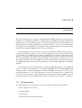
Introduction
The goal of this project is to develop a Wireless Network (IEEE 802.11) measurement point
compliant to the DPMI specification. DPMI stands for Distributed Passive Measurement
Infrastructure. It is a distributed system to monitor computer networks, mainly Ethernet, on
different points and without disturbing the measured network. It is made of Measurement
Point (MP), controller (MArC), and consumer. All connected through a network, the Measurement Area Network (MArN) which is based on Ethernet.
Each measurement point monitors one or more transmission medium using caputre interfaces (CI). When it catches a frame, it filters it using given rules, and if the frame match
it, it forwards it to a DMPI specific network, the MArN. The controller is responsible of the
behavior of the MP, it will compute the filtering rules and sent them to the MP concerned.
The consumers should get the data send by the MP, analyze them and display them to the
user. More information about the DMPI can be found in the chapter 2 and in the document
“A Distributed passive measurement Infrastructure” and the slides “DMPI API v0.6, MArC
and MP”.
The measurement point will be based on Soekris net4801-60 hardware. The net4801-60
board is a single board embed PC. It is build around AMD Geode SC1100 266MHz x86
family processor. It embed 128 Mbytes of PC133 SDRAM. Rom memory can be a Compact Flash memory or a 2.5” laptop hard drive. It has also 3 Ethernet port, 1 miniPCI and
one PCI v2.2 3.3V expansion slot. Further information about the Soekris net4801 board can
be found in chapter 3.1 the “net4801 series boards and systems. User’s manual.” in annexe C
1.1
Requirments
The Measurement point developed in this project should do following functionality :
• Auto configure at boot time.
• Capture frames
• Filter frames
• Build and Send measurement frames
6
Soekirs Based MP
• Send status messages
• Accept and act according to control messages
• Add filter
• changer filter
• Remove filter
• Flush buffers
• Use UDP/IP for messaging.
• should comply with version 0.6 and 0.7 of DPMI
Antoine Zen-Ruffinen
7
CHAPTER
2
Distributed Passive Measurement Infrastructure
This chapter contains short information about the DPMI system and it’s subsystem. It
describe what they are doing and how they interact. As said before, the goal of the DPMI
is to collect data from computer network’s data links, choose what is relevant or not using
filter, collect those data, process them and finally display result to the user.
2.1
General Architecture
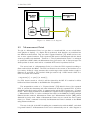
The DPMI system is made of different devices connected together with a network called
Measurement Area Network [MArN]. It is, in fact, an Ethernet network + a time synchronization system. It will be discussed more in section 2.2. The devices are connected through
the MArN are Measurement Points [MP], a Measurement Area Controller [MArC] and Consumers.
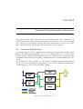
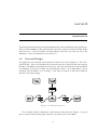
The DPMI layout is show in Figure 2.1. The devices are discussed in the following sections.
There can be one or more MP or consumers but it can be only one MArC. Of course it need
at minimum one of each to have the system working.
Figure 2.1: DPMI Architecture
8
Soekirs Based MP
2.2
Measurement Area Network
On the Measurement Area Network (MArN) are exchanged two type of PDUs. UDP packets
and Ethernet multicast frames.
UDP packet are exchanged between the MArC and the MPs. They can a MP announcing
itself to the MArC, a new filter sent by the MArC to a MP, or any other control message
defined in the DPMI specification. Those messages will be described in section 2.7.
The Ethernet multicast frames are “Measurement frames” sent by the MPs. A Measurement frames contains multiple “Capture frames” witch handle a captured PDU (that has
match a filter), its arrival time, and other info (see section 2.10). Measurement frames are
sent to the consumers. They will analyse those data and display results to the user. The
multicast address of a Measurement frame is specified by the filters.
From a hardware point of view, the MArN in nothing more that a normal Ethernet
network, all devices are connected together trough RJ45 cables and Ethernet switch. Note
that two or more “DPMI devices” can run inside the same machine ( can be for MArelayD
and MArC) or it can be on two or more machine (often the case of the MArC).
Ethernet multicast
Ethernet multicast is used to send a message to all hosts interested in in the network. An
Ethernet frame having a mulicast destination address is forwarded to all the hosts by switches
(and of course hubs). A mulicast address is identified by the bit 0 of the fist byte at one. Put
shortly, if the Ethernet address begin with an odd number it is a multicast address This mean
that half of Ethernet address are multicast addresses. For example 01:00:A3:E5:9F:81 or
05:00:A3:E5:9F:81 are both different mulicast address. Take care, a lot of mulicast address
are already used. Have a look at http://www.cavebear.com/archive/cavebear/Ethernet/multicast.html for a short list.
2.3
Measurement Area Controller
The MArC is the entity responsible for the setup of the MPs. Once a MP is connected to
the MArN and powered up, it will announce itself to the MArC. If the MP was authorized
by the user, the MArC replies with the id of the MP (called MAMP ID). This ID is unique
in the Measurement Area and is used to address the MP. Once a MP is identified, the role
of the MArC is to manage filters and to interact with the user.
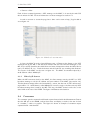
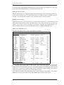
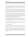
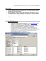
The user interface is made using a web GUI (Graphical User Interface) as shown in figure
2.2. That way it can be accessed from any where in the word, using a internet connection.
Here is a list of what the user can do using the MArC’s web interface:
• See which Measurement Point are in the Measurement Area (connected to the MArN)
• authorize a new MP
• stop a MP
• Add a new filter
• Change an existing filter
• Verify a filter
Antoine Zen-Ruffinen
9
Soekirs Based MP
• Remove a filter
Each of those command generate a UDP message on the MArC, it is sent by the web GUI
that is written in PHP. For more information on those messages see section 2.7.
It need an account to access the page, but a demo can be seen at http://inga.its.bth.se
or see figure 2.2.
Figure 2.2: MArC web user interface.
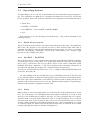
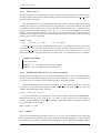
In facts, the MArC is made of tree different parts. A Deamon that listens to the UDP
messages sent by the MP, a web GUI that interact with the user and send messages to the
MP, and a mySQL database that hold filters and many informations about the MPs, like its
name, IP address, ID, etc. . . Both the demon and the web GUI are accessing this database.
The Layout of the MArC can be seen on figure 2.3. The MArC is sometime helped by a
small deamon called “MArelayD”.
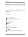
2.3.1
MArelayD demon
When the MP announces itself to the MArC, the first message sent by the MP is a UDP
broadcast message to ask the IP address and port number of the MArC (see section 2.8).
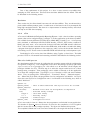
This broadcast message will not be forwarded by a router, but the rest of UDP unicast messages will be. So a small demon, called MArelayD, is used to reply to the first and only UDP
broadcast message that is send by the MP. That way, the MArC doesn’t need to be on the
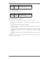
same LAN as the rest of the DPMI. The figure 2.4 illustrate this situation.
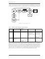
2.4
Consumer
The consumer gets the captured and filtered capture frames inside the Measurement Frames
that the MP put on the MArN, analyse those data and display a result to the user in form
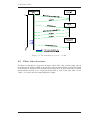
of a number, a table or a graphic. The figure 2.5 shows an example of consumer output
captured inside a web browser.
Antoine Zen-Ruffinen
10
Soekirs Based MP
Figure 2.3: MArC block diagram
2.5
Measurement Point
The job of a Measurement Point, is to get data on a monitored link, on one or both directions (simplex or duplex). If a duplex link is monitored, both direction are considered are
two different monitored link. They are called “Capture Interfaces” [CI]. A MP can have one,
two or more capture interfaces. Each captured PDU must be timestamped with the better
accuracy possible and numbered. Therefore a “Time Synchronization Device” is envisaged
to synchronise all MP within the Measuement Area (see section 2.6. A first prototype was
developed but it doesn’t work well so a standard NTP service is preferred for now.
The second task of a Measurement Point is to filter the PDU captured according to
filters received from the MArC. The PDU are filtered on the content of the headers not on
it’s content. A filter is a data structure that contain target value and bit masks to apply to
Ethernet, IP and UPD or TCP header’s fields (see section 2.9). A PDU match a filter on a
field i if it follow this condition:
targeValue[i] == pdu[i] & mask[i];
If a PDU doesn’t match on a field, it will be rejected by the MP. If it matches it will be
buffered and then forwarded to the MArN after encapsulation.
The encapsulation consist of a “Capture Header” [CH] added in front of the captured
PDU. It contains the timestamp and other informations about the captured PDU. It will be
described in details in section 2.10.1. A capture header and the PDU together are a “Capture
Frame”. Before being forwarded on the MArN, the capture frames are grouped together into
a “Measurement Frame” in order to minimise the traffic on the MArN by avoiding multiple
Ethernet header overhead. Measurement Frame and “Measurement Header” [MH] will be
discussed in section 2.10. When a Measurement Frame can not contain the next Capture
frame or a “Flush” command is received, the Measurement Frame is emitted on the MArN
using Ethernet mulitcast.
The rest of the job of the MP is handling the communication with the MArC, and check
it’s general behavior. A Measurement Point can be schematically seen in a bloc diagram as
Antoine Zen-Ruffinen
11
Soekirs Based MP
Figure 2.4: A MArN with remote MArC
Figure 2.5: A consumer output graphic
shown in figure 2.6.
2.6
Time synchronisation device
The time synchronisation devices use a GPS as a time source because it has a precision of
50 ns. A “Master” is directly connected to the GPS and sends the time to the “Slaves” or
“clients”. For compensating the propagation delay introduced by the transmission lines, a
pulse is sent and to a loopback and the time for a round trip is measured. Then the half
of the round trip time is subtracted to the time received. This way, a slave or a client has
exactly the same time that the others slave and clients.
More information about the Time synchronisation system can be found in the document
“Time and frequency synchronisation”.
Antoine Zen-Ruffinen
12
Soekirs Based MP
Figure 2.6: Block diagram of a Measurement Point
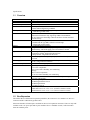
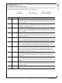
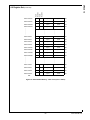
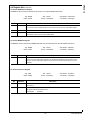
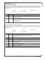
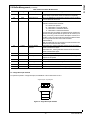
2.7
Messages used in DPMI
This section describe the messages exchanged between the MArC and the MP. Each message
begin with a 32 bits “type” filed that identify the content of the message. The following
table describe the messages that are use in DPMI.
type
1
2
3
4
5
6
7
8
9
Contents
MP address & MAMP ID
status of MP
new Filter
changed Filter
Dropped Filter ID
Verify Filter
Verify All Filters
Terminate MP
Flush buffers
Related message structure
MAinitialization, see 2.7.2
MPstatus, see 2.7.3
MPFilter, see 2.7.4
MPFilter, see 2.7.4
none
MPVerifyFilter, see 2.7.5
none
none
none
Note that :
• The messages between MArC and MP are UDP datagrams.
• Following descriptions doesn’t include UDP/IP or Ethernet headers.
• The first 32 bits field in all messages, excepts MAINFO, is a identifier for the content
of the message.
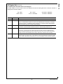
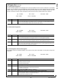
2.7.1
MAINFO
This is the message sent by the MArelayD to the MP on the initialisation sequence (see section 2.8). When the MP contact the MArelayD, it just needs to “poke” it with a empty UDP
packet but on the right port number. Then the MArelayD reply with a MAINFO message.
It contains the IP address & port number of the MArC to locate it.
Antoine Zen-Ruffinen
13
Soekirs Based MP
Name
version
address
port
database
user
password
2.7.2
Size
32 bits
16 chars
32 bits
64 chars
64 chars
64 chars
Description
Version of the DPMI used : 1=0.5, 2=0.6,. . . , big endian.
IP address of the MArC, coded in ASCII.
UDP port of the MArC, big endian.
mySQL database name, used for DPMI v0.5.
mySQL user name, used for DPMI v0.5.
mySQL password, used for DPMI v0.5.
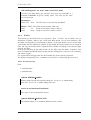
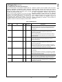
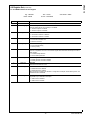
MPinitialization
This message is sent by the MP to the MArC to announce itself. It contains information
about the MP like his name, IP address & UDP port, MAC address, abilities , etc. . . The
MArC reply with the same message but set the MAMPid field that assign the MP’s unique
identifier. If the MP is unauthorized, the MAMPid field returned is empty (an empty string
“”). See section 2.8 for more information the initialization sequence.
Name
type
mac
name
Size
32 bits
8 bytes
200 chars
ipAddress
port
maxFilters
32 bits
16 bits
16 bits
noCI
MAMPid
16 bits
16 chars
2.7.3
Description
Message type, always 1, little endian.
MAC address of the MP.
Name of the MP. Must be a single word despite
the 200 chars.
IP address of the MP, big endian.
UDP port the MP is listening to, litte endian.
Maximal number of filter that the MP can manage,
little endian.
Number of Capture Interface the MP has, little endian.
MP’s unique identifier. Set by the MArC.
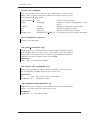
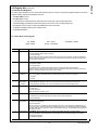
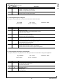
MPstatus
This is sent by the MP once every second. It has two roles. First, tell that the MP is still
on-line and running. Second, give some statistic about the MP and the current measurement.
Name
type
MAMPid
noFilters
matched
Size
32 bits
16 chars
32 bits
32 bits
Description
Message type, always 2, little endian.
MP’s unique identifier.
Number of filters active in the MP.
Number of PDU that matched one of the filter,
XX endian.
noCI
32 bits
Number of Capture interface on the MP.
CIstats
1100 chars String that give some more stats, see bellow.
The CIstats string is containing statistical information on all caputre interfaces. It
syntax is :
CI1:Recv.Packets:Filtered.Packets:BufferUse
CI2:Recv.Packets:Filtered.Packets:BufferUse
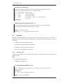
2.7.4
MPFilter
Contains a filter. It can be a new or a changed filter send by the MArC. A new filter has type
3 and a change in a filter has type 4. The data structure of a filter is described in section
2.9.
Antoine Zen-Ruffinen
14
Soekirs Based MP
Name
type
MAMPid
theFilter
2.7.5
Size
32 bits
16 chars
168 bytes
Description
Message type, 3 or 4, little endian.
MP’s unique identifier.
The new or changed filter. (see 2.9)
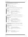
MPVerityFilter
Mean that a filter should be checked.
Name
type
MAMPid
theFilter
2.8
Size
32 bits
16 chars
168 bytes
Description
Message type, always 6, little endian.
MP’s unique identifier.
The filter to be checked. (see 2.9)
Initialization sequence
The figure 2.7 show a typical initialization sequence. The operation goes so :
1. The MP contacts the MArelayD. A empty datagram on the right UDP port, 1500, is
enough.
2. The MArelayD replies with the address of the MArC.
3. The MP annonces itself to the MArC using a MPinitialization message. It contains the
address of the MP.
4. If the MP is authorized, the MArC reply with a MPinitialization message that contains
the MAMP ID unique identifier. If the MP is unauthorized (or unknown) the MAMP
ID is empty.
5. If there are already some filters for the MP in the MArC database, they will be sent by
the MArC.
The MP is now ready to work. Any incoming PDU on the monitored link will be processed
and forwarded to the consumers.
Antoine Zen-Ruffinen
15
Soekirs Based MP
Figure 2.7: The initialization sequence of a MP
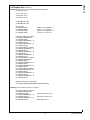
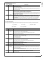
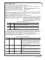
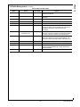
2.9
Filter data structure
The filters are handled as a large data structure, called “FPI”, that contains target value &
bit masks that should be applied to the headers of the incomings PDUs. An important filed
of the Filter data structure is the filed index (see table below). It gives information on which
field should be checked or not. Each field is identified as a bit of the index filed. So the
“index” of a field is the the corresponding bit’s weight.
Antoine Zen-Ruffinen
16
Soekirs Based MP
Name
filter id
index
Size
32 bits
32 bits
Description
Filter identifier. Used to reference the filter.
Specify witch field should be check. Etch bit
represent a field.
CI ID
VLAN TCI
ETH TYPE
ETH SRC
ETH DST
IP PROTO
IP SRC
IP DST
SRC PORT
DST PORT
8 chars
16 bits
16 bits
6 bytes
6 bytes
8 bits
16 chars
16 chars
16 bits
16 bits
Filter by capture interface name, index 512.
VLAN ID, index 256.
Ethertype, index 128.
Ethernet source address, index 64.
Ethernet destination address, index 32.
IP protocol filed, index 16.
IP source address, coded in ASCII, index 8.
IP destination address, coded in ASCII, index 4.
TCP or UDP source port, index 2.
TCP or UDP destination port, index1.
VLAN TCI MASK
ETH TYPE MASK
ETH SRC MASK
ETH DST MASK
IP PROTO MASK
IP SRC MASK
IP DST MASK
SRC PORT MASK
DST PORT MASK
16 bits
16 bits
6 bytes
6 bytes
8 bits
16 chars
16 chars
16 bits
16 bits
VLAN ID bit mask.
Ethertype bit mask.
Ethernet source address bit mask.
Ethernet destination address bit mask.
IP protocol filed bit mask.
IP source address bit mask, coded in ASCII.
IP destination address bit mask, coded in ASCII.
TCP or UDP source port bit mask.
TCP or UDP destination port bit mask.
DESTADDR
DESTPORT
TYPE
22 chars
32 bits
32 bits
Destination Address.
Destination Port.
Consumer stream type.
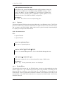
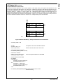
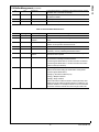
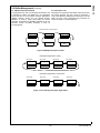
2.10
Ethernet Frames in DPMI
RAW Ethernet frames are sent by the MP to the consumers. They contain captured PDUs
and related information. Each Ethernet frame carries only one Measurement Frame. A Measurement Frame can carry one or more Capture frames. Figure 2.8 shows this process. They
are sent using Ethernet multicast (see 2.2). Following description doesn’t include Ethernet
headers.
The destination multicast address of the Measurement frame is depending on the filter
rules. PDU matching a rule must be forwarded to a specific consumer. So matched PDUs
should be sorted according to the filter they match, then sent to the right multicast address.
2.10.1
Capture Header
The capture Header contains the PDU’s timestamp, the capture interface used, the MP ID,
the PDU size on the link and the captured length.
Antoine Zen-Ruffinen
17
Soekirs Based MP
Figure 2.8: Encapsulation process
Name
ci
mampID
sec
psed
frameLength
capLength
2.10.2
Size
8 chars
8 chars
32 bits
64 bits
32 bits
32 bits
Description
Used Capture Interface name.
MP’s unique identifier.
PDU timestamp, seconds since 1st jan 1970.
PDU timestamp fractional part in picoseconds.
PDU size on the monitored link.
Captured bytes count. (a PDU can be cut)
Measurement Header
Give information about the content of the Measurement frame like DPMI protocol version,
sequence number, numer of capture frames insde the measurement frame and if the frame
follow a flush command or not.
Name
seqNumer
pktNbr
flush
majVer
minVer
Size
32 bits
32 bits
32 bits
32 bits
32 bits
Antoine Zen-Ruffinen
Description
Frame’s sequence number.
Count of Capture Frame inside this Measurement Frame.
Say if this Measurement Frame is send after a flush message.
DPMI major version number (vN.x).
DPMI minor version number (vx.N).
18
CHAPTER
3
Environment
This chapter talk about what the MP will need to run. A program need 2 things to run : A
hardware and a software environement (often an operating system). They will be discussed
in the following sections.
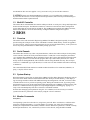
3.1
Hardware
The hardware is for a part fixed by the project requirements: it must use the Soekris net4801
board. As this project should implement a WLAN measurement point, we also need a WLAN
card. The choice of the WLAN card will be discussed in section 3.1.2.
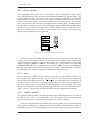
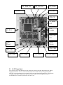
3.1.1
Soekris net4801
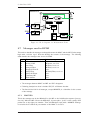
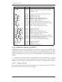
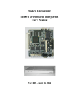
The Soekris net4801 board is a single board, low power, embedded PC designed for telecommunication application based on Ethernet (see fig. 3.1). The size of the board is only 132 x
145 mm (5.2 x 5.7 inch). It is built around the AMD Geode SC1100 processor which is an
Intel class 586 compatible CPU with MMX. The board exists in two version, the net4801-50
and net4801-60. The net4801-50 board has a 128MB of RAM and the net4801-60 256MB.
This project use the 128MB version.
Here is a short list of the features of the board :
Processor
Memory
Network
Input/Output
Power consumption
Storage
Expansion
Operating temperature
Single Chip AMD Geode 266 MHz.
128 MB PC133 SDRAM
3 100BaseT (NS DP83816 chipsed)
2 RS232 serial line
12 programable general purpose I/O.
1 USB port
max 5W
CompactFlash type I/II socket.
Optional 2.5” IDE hard-drive.
1 PCI 2.2 3.3V slot
1 miniPCI typeIIA socket
0 C - 60 C
19
Soekirs Based MP
More info about the net4801 board can be found in the document “net4801 series boards
and systems. User’s Manual” in appendix C.
Figure 3.1: the Soekris net4801 board
3.1.2
WLAN card
There are 4 constrains for the chose of the WLAN card.
• It must be compatible with the net4801 witch has a 3.3V PCI V2.2 bus.
• It must be orderable in Sweden.
• It must be IEEE802.11a/b/c able.
• Documentation or open source driver should be available.
The problem with WLAN chipset, is that the manufacturer never release some public
documentation about there products. They say it is because of some country’s regulation.
All WLAN chipset can be tuned to any frequency in the 2.4GHz band and maybe more frequencies, and some of them are restricted in some countries. They don’t want a programmer
to tune its WLAN card to a forbidden frequency with the help of the documentation. Despite
of this, some manufacturer are releasing the documentation to a specific group of developer.
They used it and wrote an open source driver but without publishing the documentation.
Some manufacturer wrote a linux driver, some time open source. Some other never did
anything, but a reversed engineered open source driver is available.
Most of the cards available in europe are mainly based on chipsets form tree manufacturer:
Broadcom, Alteros and Ralink.
Broadcom based cards
The open source driver for Broadcom chipset based card was reversed engineered from a
closed source Apple Mac driver. The data collected and the reverse engineering process can
Antoine Zen-Ruffinen
20
Soekirs Based MP
be found at http://bcm-specs.sipsolutions.net/. A lot of things are missing in it. The open
source driver is available at http://bcm-specs.sipsolutions.net.
Atheros based cards
Atheros chipset seem to be largely used by card manufacturer, a lot of PCI card are based on
it and most of miniPCI card. A open source driver is available at http://madwifi.org witch
is based on documentation released to the madwifi developer team by Atheros.
Ralink based cards
Ralink released a linux open source driver, it can be downloaded at http://www.ralinktech.com/ralink/Home/Support/Linux.html. But this driver is very basic and there is one driver by
chipsed. That’s why a team of developer are writing a enhanced and unified driver on the
basis of Ralink’s driver. It can be downloaded at http://rt2x00.serialmonkey.com.
Chose of a WLAN card
The following table is a list of the card available in Sweden.
Company
Model
Mode Chipset Voltage
From Dustin
3COM
3CRDAG675B
A/B/G Atheros 3.3V
CISCO
D-LINK
DWA-547
B/G/N no info no info
D-LINK
DWL-AG530
A/B/G Atheros no info
D-LINK
DWL-G510, V.C2
B/G Ralink
no info
D-LINK
DWL-G520
B/G Atheros 5V
D-LINK
DWL-G520M
B/G Atheros 3.3V
INTEL
3945ABG
A/B/G
not PCI2.2
INTEL
4965AGN
A/B/G
LINKSYS
WMP54G, V.4
B/G Ralink
LINKSYS
WMP200-EU
B/G no info
LINKSYS
WMP300N-EU
B/G/N no info
LINKSYS
WMP54GS-EU, V.4 A/B/G Ralink
both
NETGEAR WG311IS, V.1
B/G Atheros both
NETGEAR WG311TIS
B/G Atheros both
NETGEAR WN311B
N
NETGEAR WN311T
N
NETGEAR WPN311IS
B/G A Atheros both
ZYXEL
NWD-370N
N
From InWarehouse
Belkin
F5D7000YY
B/G Ralink
both
OK?
No
No
No
Yes
No
Yes
No
No
Yes
No
No
Yes
Yes
Yes
No
No
No
Yes
This table is the state of the Swedish market in October 2007. Note that some board
have different chipset depending on the version. Often Broadcom chipset are replaced by
Ralink chipset on newer version. Because of the reversed engineered driver, Broadcom based
cards are not considered. A Ralink based card was preferred to Atheros based card, because
of the manufacturer open source driver that Ralink provide.
Two cards were ordered after verification of the version number by the retailer : The Linksys
WMP54G and the D-Link DWL-G510. The WMP54G was used for the project.
Antoine Zen-Ruffinen
21
Soekirs Based MP
3.2
Operating System
The first thing to do is to choose an environment for the measurement point’s program to
run. The constraints are: Must run on a headless (no keyboard, no screen) PC, and it must
be free of charge. After a bit of search, 4 solution to run a program on the soekris were found:
• Stand alone
• FreeDOS + FreeRTOS
• Free UNIX like : Linux, freeBSD, openBSD, MINIX,. . .
• eCos
Each solution as its own advantage and disadvantage. They will be discussed in the
following sections.
3.2.1
Stand Alone program
This is of course the best solution to have the most power from the processor. The application
will be the only program to run and will not have to share resources with other task or
scheduler. But there is a huge drawback with stand alone program: It need to do everyting
from the very begining: Bootloader, TCP/IP stack, device drivers, etc. . . Having a sigle
process can also complicate the work.
3.2.2
FreeDOS + FreeRTOS
One of the first idea is to use a small real time operating system (RTOS). The list of the free,
or better open source, is really small. One of the most famous is FreeRTOS. If FreeRTOS
run on a PC, it will need to run on top of DOS. Ther is a free version of MS-DOC called
FreeDOS. DOS have a limitation : it run only in 16 bits mode of the IA-32 architecture. It
is a little wast full when the program run a 32 bits Pentium class processor.
The PC port of FreeRTOS was written for a C/C++ compiler called OpenWATCOM, witch
is also free, but really old.
An other problem of the use of FreeRTOS on top of FreeDOS is the lack of TCP/IP stack
or any network facilities. If network is needed, then it need to download a free network stack,
like LwIP or uIP and to implement it on FreeRTOS. It will also need to develop driver for the
network cards. In this project we have to use two different network adapter. Programming a
driver for both represent a significant amount work.
3.2.3
Linux
When looking for a free operating system, one of the first idea is the well-know Linux. Linux
has a lot of advantage: it is well supported by the developer community, it is easy to fined
some (or a lot) documentation or help on any topic, it is easy to program and a lot of developer have used it on the Soekris board and it work on it without problem. A lot of tutorial
are on the web about it and in annex D. But one we can ask ourself if linux in not to heavy
for such a small application? How will his performance be ? Linux was designed to be used
on a desktop/server PC. Will not the kernel spend to much time on task that are not useful
in this project (like file system or memory management) ?
Antoine Zen-Ruffinen
22
Soekirs Based MP
One of the requirement of this project, is to have a more accurate as possible timestamping on PDU arrival time. This need some real-time abilities from the kernel. This will
be discussed in the following section.
Real-time
Since version 2.6, the Linux kernel has some soft real-time abilities. They are enhanced by a
patch called realtime-preempt patch. It enable most of the kernel code to be preempted and
bring high resolutions timers. But there is no improvement in interrupt latency time witch
can help us in PDU time stamping.
3.2.4
eCos
eCos stand for Embeded Configurable Operating System. It his a hard real-time operating
system, that can be configured using ”packages” to fit the application as the best as possible.
It it available for many different CPUs like IA-32, ARM, MIPS, PowerPC, etc. . . It incorporate
many standard, or well-known API like POSIX threads, µT RON , BSD socket, standard C
library and many more. eCos comes with its how bootloader and ROM monitor called redBoot. This bootloader is network able and has GDB stubs, with enable to download & debug
a program from the host platform to the target very easily. In fact the bootloader function is
not working on a PC. But it can be loaded with GRUB and still can help on development cycle.
Developing for eCos can be done from Window, using Cygwin, or from Linux. The build
process of eCos in a bit unusual but interesting and will be described in the following section.
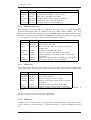
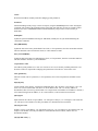
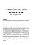
The eCos build process
Any development with eCos start by configuring the operating system with the configuration
tool (called “configtool”). The configuration tool look in the package repository (the folder
/opt/ecos/ecos-vx.x/packages) for a file called ecos.db witch list all the targets and
packages available for eCos. The first setp is to select the target needed and a set of base
package using a template. Then package(s) can be added or removed to fit the application
as its best and configure them. A package is a set of function or API and some hardware
driver. They are package like “CAN support”, “Standard C library”, “Network support”,
etc. . . When this job is finish, the programmer save its configuration and build it. Let say he
chose the name myConf as configuration name. It will result in the following tree, witch is
called “build tree” :
myConf.ecc
myConf_build/
myConf_install/
include/
lib/
target.a
???.a
targed.ld
myConf_conf/
: This is where makefiles and objects files are storred.
:
:
:
:
:
:
Headers files used for devlopement & compilation
Contains binary libarys
eCos main libary
Auxilary libary
Linker script.
Configaration files.
eCos is now ready in form of a library that the programmer can link with its user application.
The headers in myConf install/include are used for the compilation of eCos together
with the source files in the package repository. The figure 3.2 illustrate this process.
The compiled & linked user code can now be download to the target with the help of redboot
Antoine Zen-Ruffinen
23
Soekirs Based MP
trough a serial interface or network. It can be also written to the ROM (the Compact Flash
in our case) and started from there. A sample makefile and code can be found in annexe E.
Figure 3.2: eCos build process
3.2.5
Chose of the software environement
Here is a summary of the avaiable platfom :
OS
Stand alone
FreeDOS + FreeRTOS
Toolchain No toolchain
OpenWATCOM
Positiv
-Fast exectution
Negativ
-Hard & long development
-No TCP/IP stack
-OpenWATCOm
compiler
Linux
eCos
GNU Gcc
-Easy to develope
-Widely used
-WLAN driver avaiable
GNU Gcc
-RTOS
-Fast Exection
-APIs avaiable
-Heavy
-Fast
developement cycle
-No WLAN driver
-No relase since
2002
The table above a summary of the available platforms is listed, together with their advantages and disadvantages. Based on this, the stand alone and FreeRTOS were not considered.
Mainly due to the amount of work required, and the toolchains used. Linux was choosen for
the first release, because it is an easy to develop, multithreaded and networked environment.
Drivers for both network interfaces used are also available. Then eCos will be used for a
enhanced version. The application use C standard library, POSIX pthread and BSD sockets,
then it is easy to port it from Linux to eCos, because both implements those API.
Antoine Zen-Ruffinen
24
CHAPTER
4
Implementation
This chapter discuss the design and the implementation of the measurement point application,
witch is called wlanMP. It talk generally about the Linux version because the initial design
was made on it. The eCos version is mostly similar to the Linux one, they are only a few
differences. Those are discussed in the section 4.7.
4.1
General Design
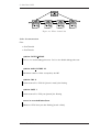
The application use 5 threads, the interaction of them can be seen in figure 4.1. The “Controller Thread”. Once a few initialization in the main are done, it take the hand and announce
the MP to the MArC (as described in section 2.8). Once the communication with the MArC
is established, its work is to handle the communication with it. It is responsible to get all
messages from the MArC. If, for example, a new filter is received, it will add it using the
function of the filer package.
Figure 4.1: Thread interaction
The Controller Thread is helped by a other thread, called “Beacon Thread”. It’s job is
just to send the status message (see section 2.7.3) each second to the MArC.
25
Soekirs Based MP
The remaining three threads work sequentially, to do the Capturing-Filtering-Forwarding
process. They are called respectively “Capture Thread”, “Filter Thread” and “Sender
Thread”.
The capture thread get all PDUs from the capture interface and the corresponding time
stamp. It put the PDU data in a buffer, where it will stay until the end of its life in the MP.
Then it fill a descriptor that holds the name of the capture interface, the time stamp and a
pointer to the PDU in buffer. When this is done, it put this descriptor in a queue for the
filter thread.
The filter thread get the captured PDU from its queue and apply all available filter to it.
If the PDU match a filter, then the thread fill the destination consumer address in descriptor
and put it in the queue for the sender thread. If the PDU fail all filters rules, then it is
rejected and the PDU’s buffer marked as available again. The filters are kept as a chained
list. When a new filter is received by the controller, it will be added to the list. Note that the
filter list is chained in both direction, because it make the job of removing a filter much easier.
The sender thread sort filtered PDU in different local buffers according to consumer address written in the descriptor. If the consumer address of incoming PDU is not know, then
the thread will create a new buffer for it. When creating a new buffer, it will also create the
corresponding Measurement Header. Each buffer has the size of an Ethernet frame. When a
PDU is copied in a buffer, the corresponding Capture header is also build. When the buffer
is full then it is send to the consumer and filled again from the beginning.
Each thread will be discussed more in details in the section 4.4.
For making the code more readable and easy to maintain, some part of the code are as
“Modules”. Those modules help also to make the code more portable, because they contains
most of the platform specific code. Only a few system call are outside those modules. Those
module are to abstract part of the code like network socket calls, threads and queue. Those
modules are described in section 4.5.
The whole code is written in C, and can be compiled using a makefile just typing make
in the Relase directory. The code as also a on-line documentation created with the doxigen
system, it can be found in the doc/html directory.
4.2
Time stamping
Time stamping is one of the aim of the measurement point. To have precise time stamping
we need a good time source and to have the time stamping done in the code as near from the
event source as possible. The better place will be at the beginning of the interrupt service
routine.
The Linux stack enable to get PDU time using the ioctl() call. The driver has to provide
the time stamp in form of a ktime struct in the socket buffer. Socket buffer are the structure
used on Linux to exchange data between network driver and the kernel. If the driver doesn’t,
then the kernel will provide a the current system time at the time the ioctl() is called.
Drivers that adding timestamps in the socket buffer are rare, because application needing it
are also rare.
Antoine Zen-Ruffinen
26
Soekirs Based MP
4.2.1
Time source
For time stamping, we need to know the time. A PC under Linux provide two common source.
The time stamp counter of the pentium family processor and the function ktime get real()
provided by the Linux API.
The time stamp counter of the pentium family processor is a 64 bits register that is just
counting the CPU clock cycle since the CPU was powered up. Note that if the CPU is turned
in sleeping mode in order to save energy, the time stamp counter stop. It provide then a
relative clock source with a precision of 2 · TCP U = 2/fCP U and its resolution is one CPU
periods. As this counter is relative to the CPU power up time and in CPU period unit, it
need some processing in order to have absolute time in seconds. The value of the time stamp
counter can be read as following :
UINT64 stamp;
__asm__ __volatile__(‘‘rdsc’’ : ‘‘=A’’ (stamp));
ktime get real() return a structure, called ktime containing the current system time
in second since 1 st January 1970 on 32 bits and the fractional part in nanosecond on 32
bits. ktime get real() was introduced in kernel 2.6.17. The resolution of it is on most
system 1us despite of the fractional part in nanoseconds. The structure ktime is as follow:
typdef struct ktime
Linux kernel time.
UINT32
UINT32
4.2.2
sec
nsec
Seconds since 1st January 1970
Fractinal part in nanoseconds.
Modified Ralink driver for time stamping
As noted before, the driver need to do the time stamping in order to have a suitable accuracy.
Therefore, the Linux Ralink wireless card driver was modified to do this. The modification is
not quite small, and consist of just adding two line in the right position.
First in the interrupt service routine, called rt61 do irq() in file rtmp main.c, the time
is written in a global 32 bits unsigned variable on the first line of the function, just after
variable declarations (line 216). Like this :
stamp = ktime_get_real();
Then if the interrupt is recognized as a end of frame reception, the function RTMPHandleRxDoneInterrupt() in file rtmp data.c is called. It that function the socket buffer in
created. It was modified to copy the time stamp sorted temporarily in the global variable in
the socket buffer on line 1216 :
skb->tstamp = stamp;
4.3
main
There is not something special about the main, it do only a few initialization job, then start
the controller thread. It start by getting the application PID and displaying it. This is useful if
the application is tuned into a daemon as explained later. Then it get the IP and MAC address
Antoine Zen-Ruffinen
27
Soekirs Based MP
of the MArN side interface, those are used later in the MP announcement sequence. It set all
other global variable to NULL to avoid unexpected behaviours. Then, if the user required it
by specifying it by the ’-d’ option on the prompt, it turn the application into a daemon using
Unix fork() function. When all this job is done it start controller thread. In facts the main()
become the controller thread by calling its implementing function (controllerThread()).
4.4
Thread
4.4.1
Controller
The controller thread is the first thread to run. It initiate the communication with the MArC,
using the MArelayD, a described in section 2.8. When the announcement of the MP to the
MArC is done, the controller thread start the others threads and continue to accept messages
from the MArC. According to the message type (see 2.7), it take the necessary action and
wait for the next message.
Code documentation
Files :
• controllerThread.h
• controllerThread.c
#define CONTROLLER DEBUG
Enable Controller Thread and function Debug info
Set it to 1 to enable debug print-outs. Set it to 0 to disable debug print-outs.
void* controller Thread(void* args)
Controller Thread code.
Parameters :
void* args Its own thread descriptor
void startMP()
Start the Capture by starting the capture, filter and sender threads. It also
create the message queue before starting threads.
void stopMP()
Stop the capture by stopping all threads except controller thread. It also
delete the queues afterwards.
Antoine Zen-Ruffinen
28
Soekirs Based MP
void mpAnnouncement(int sock)
This function first contact the MArelayD using UDP broadcast to know the
IP address and UDP port of the MArC, using a MAINFO message. Then it
contact the MArC, and get his MAMP ID. This function set globals marcIpAddr, marcPort, dpmiVer, sqlPort, sqlDbName, sqlUser, sqlPass. Those
global are related to the DMPI and MArC configuration.
Parameters :
int sock the socket to use for send/receiving data.
4.4.2
Capture
This thread capture PDUs from the monitored link using a raw Ethernet socket. The PDU is
placed in a buffer and a descriptor is filled with the capture interface name, the time stamp,
and a pointer to the PDU’s buffer. When this is done it place the newly created descriptor
in a queue (filterQ) for the filter thread.
Code documentation
Files :
• caputreThread.h
• captureThread.c
extern int capPacketCount
The count of captured packets.
#define PACKET CATCHER DEBUG
Set it to 1 to enable debug print-outs. Set it to 0 to disable debug print-outs.
void capture Thread(void* args)
This thread capture all data on the monitored link using a RAW socket.
Parameters :
void* args Thread parameters, here its own descriptor.
4.4.3
PacketFilter
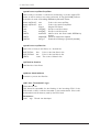
This thread has the heaviest job, the PDUs filtering. Its work can be described by the flow
chart in Figure 4.2. It get a PDU from its queue (filterQ) and filter it according to the
filters the MP has in memory. If the PDU pass one of the filtering, it is forwarded to the
sender thread, after have updated the destination address in the descriptor according to the
matched filter. If the PDU fails all rules then it is rejected, its buffer marked a free and its
descriptor destoyed.
Antoine Zen-Ruffinen
29
Soekirs Based MP
The filtering itself is very easy. Each received filter rule is converted to two bits arrays
analogue to Ethernet/IP/(TCP—UDP) headers. One for the mask, one for the value to
compare to. Then each byte of the captured PDU’s header is masked and compared with
the rules value into a loop. If one of those comparison failed, then the PDU failed the ruler.
But some PDU have Ethernet “VLAN tag” witch made the work a little bit more complicated. Since IEEE802.3q, Ethernet frames can have VLAN tags. VLAN tags are use to make
Virtual LANs. A network using VLANs can have two or more virtual LANs sharing the same
hardware. The different virtual LANs are identified by there VLAN tags. The VLAN tag is
signalled by a special Ethertype with has the value 0x8100. The VLAN tag is 2 bytes and
direct follow the Ethertype. So having VLAN tag make the Ethernet header 2 byte longer.
That forbidden to use a simple loop for filtering the PDU’s headers. First to determinate
if the filter rule and the captured PDU have VLAN. If both have or not VLAN, then the
appropriate filtering can be done using the appropriate algorithm.
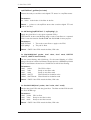
Figure 4.2: Filtering process
The filters are kept in a chained list. Each filer is store with its “ready to use” mask &
target value array and the original filter structure received from the MArC. The chained list
is holed by a descriptor and is bidirectional. This make the work of deleting a filter easier,
it is easy to get both pair on the side of the deleted filter and to link them. The filter list is
shown on figure 4.3.
Antoine Zen-Ruffinen
30
Soekirs Based MP
Figure 4.3: Filter chained list
Code documentation
Files :
• filterThread.h
• filterThread.c
#define FILTER DEBUG
Set it to 1 to enable debug print-outs. Set it to 0 to disable debug print-outs.
#define MAX FILTERS 16
Maximum number of filter accepted by the MP.
#define FAIL 0
Value returned if a PDU fail (doesn’t match) the filtering.
#define PASS 1
Value returned if a PDU pass (match) the filtering
extern int matchedPacketCount
Number of PDU that pass the filtering (match a filter)
Antoine Zen-Ruffinen
31
Soekirs Based MP
typedef struct mpFilterS mpFilter
Hold a ready-to-use filter. It will be use for filtering. It old the original FPI
struct as well as ready-to-use value and mask. A flag (hasVLAN) indicate
if the filter is made for handling IEEE802.1q Ethernet frames.
struct mpFilterS*
struct mpFilterS*
FPIT
char
char
UINT8
next
prev
orignal
value[40]
mask[40]
hasVLAN
UINT8
UINT16
dstAddr[6]
dstType
Point to the next mpFilter
Point to the previous mpFilter
Original FPI struct
Ready-to-use filter values
Ready-to-use filter mask
Indicate that the filter handle IEEE801.1q
frames.
Ethernet destination Address
Destination Ethertype (Generally 0x0810)
typedef struct mpFilterList
Hold a list of ready-to-use filters, as a chained list
mpRTUFilter
mpRTUFilter*
UINT8
first
last
count
Point to the first filter in list
Point to the last filter in list
The count of filters in list
mpFilterList filterList
Hold the list of the filters
mpMutex filterListMutex
A mutex to protect the filter list
void* filter Thread(void* args)
Filter thread code.
This thread is responsible for the filtering of the incomings PDU. If the
PDU match a filter, it will be forwarded to the sender thread. Else it will
be discarded and the memory used by the PDU freed.
Parameters :
void* args Thread own descriptor
Antoine Zen-Ruffinen
32
Soekirs Based MP
int addFilter(FPIT* filter)
Add a filter to the filter list.
This function add the given filter to the filter list and compute his read-touse value for faster filtering.
Parameters :
FPIT* filter The filter as received from the MArC.
Return : The index of the filter in the filter list.
void changeFilter(int index, FPIT* newFilter)
Change a filter in the filter list
This function change the filter designed by the given index and re-compute
its read-to-use value.
Parameters :
int
index
FPIT* newFilter
The index of the filter to change
The filter as received from the MArC.
void removeFilter(int index)
Remove a filter from the filter list.
This function remove the filter designed by the given index from the filter
list.
Parameters :
int index The index of the filter that should be removed from the filter list.
int findFilter(int filterID)
Find a filter in the filter list.
This function look for a filter with the given filter ID and return its index.
Parameters :
int filterID The filter identifer
Return : Index of the filter in the list
FPIT* getFPI(int index)
Give a pointer to the original FPI struct designed by the given index
Parameters :
int index Index of the filter in the list
Return : a ponter to the original FPI struct
Antoine Zen-Ruffinen
33
Soekirs Based MP
mpRTUFilter* getFilter(int index)
Return the ready-to-use filter and original FTI struct in a mpFilter struct.
Parameters :
int index index Index of the filter in the list
Return : pointer to the mpFilter struct that contains original FTI and
read-to use data.
int doFiltering(mpRTUFilter* f, mpCapMsg* p)
Apply the given filter f to the given captured PDU p.
This function do the actual filtering using a ready-to-use filter on a captured
PDU. It use the function filterNoVLAN and filterVLAN for that propose.
Parameters :
mpRTUFilter*
mpCapMsg*
f
p
The ready-to-use filter to apply to the PDU
The pdu to filter
Return : PASS if the PDU match the filter, FAIL else.
int filterVLAN(char* packet, char* value, char* mask, UINT16
vlanTCI, UINT16 vlanTCImask)
Do the actual filtering, with VLAN tag. Do the actual filtering of a PDU
using a filter that is made for Ethernet frame that has a IEEE802.1q VLAN
TAG. If the Ethernet frame has no VLAN TAG it will fail the filtering.
Parameters :
char*
packet
char*
value
char*
mask
UIN16 vlanTCI
UIN16 vlanTCImask
The PDU to filter
Ready-to-use filter value
Ready-to-use filter mask
Filter Virtual lan indenfier value
Filter Virtual lan indenfier mask
Return : PASS if the PDU match the filter, FAIL else.
int filterNoVLAN(char* packet, char* value, char* mask)
Analyse the given PDU with the given filter. The filter and the PDU should
not have VLAN tags.
Parameters :
char* packet
char* value
char* mask
PDU to filter
Ready-to-use filter’s value
Ready-to-use filter’s mask
Return : PASS if the PDU match the filter, FAIL else.
Antoine Zen-Ruffinen
34
Soekirs Based MP
void fpi2array(char* val, char* mask, struct FPI* filter)
Convert a FPI fliter struct into two byte array that are compatible to a
standard ETHERNET/IP/(TCP—UDP) paket. One array for the value,
one for the mask.
Parameters :
struct FPI* filter
The FPI stuct as received from the MArC.
Return : PASS if the PDU match the filter, FAIL else.
char*
val
Ready-to-use filter’s value to write in
char*
mask Ready-to-use filter’s mask to write in.
4.4.4
Sender
This thread get the PDUs that have matched a filter. It hold a list of buffers, one per
destination consumer. When it get a PDU from filter thread, it look at its descriptor, find
the buffer corresponding to its destination address. If the right buffer can’t be found, build
a new buffer with the destination address. It then builds the capture header for the captured
PDU and copy the header and the captured PDU in buffer, according to the capture length
given by the filter.
If the space remaining in the buffer doesn’t fit the PDU, then the buffer, is flushed. This
mean it complete the Measurement header with the missing data’s, send it to the consumer,
and empty it again.
If a captured PDU is bigger than the whole buffer size, then it will be truncated.
The buffer’s descriptors (struc sendBuffer) are hold in a chained list (bufferList).
Code documentation
Files :
• senderThread.h
• senderThread.c
#define SENDER DEBUG
Enable sender Thread and function Debug info. Set it to 1 to enable debug
print-outs. Set it to 0 to disable debug print-outs
extern int measurementFrameCount
The count of sent measurement frames.
#define BUFFER LENGTH 1514
Send buffer length, for a maximum Ethernet frame content
Antoine Zen-Ruffinen
35
Soekirs Based MP
typedef struct sendBuffer
This data structure hold a buffer for the senderThread. It associate the
buffer, with a consumer destination address and hold the amount of byte
and captured PDU in the buffer
struct sendBuffer s*
UINT8
next
dstAddr[6]
UINT16
int
int
unsigned char
dstType
byteCount
pktCount
buffer[BUFFER LENGTH]
Pointer to the next buffer
Destination address corresponding to this
buffer
Ethertype corresponding to this buffer
Amount of databyte in buffer
Amount of PDUs stored in buffer
Local buffer to store data before send them
extern senderBuffer* bufferList;
Pointer to the first buffer.
void sender Thread(void* args)
Sender thread code. This thread build a capture header for all PDU received
from the filter thread and store the in a local buffer. Once this buffer is
full, it build a measurement frame and send it on the MArN using Ethernet
multicast to all the consumers present on the MArN.
Parameters :
void* args Its own thread descriptor
void flush(int sock, senderBuffer* sb)
Flush the given buffer sb. When a buffer is flushed, it’s data are send to
the corresponding consumer using the given socket sock.
Parameters :
int
sock
sendBuffer* sb
The socket to use for transmission.
The buffer to flush
void makeNewFrame(senderBuffer* sb)
Reset memory (set to 0x00) of the given buffer and build the Measurement
Header. Then sent its byte & packet count to zero
Parameters :
sendBuffer* sb
Antoine Zen-Ruffinen
The buffer to reset
36
Soekirs Based MP
senderBuffer* getBuffer(UINT8* address, UINT16 type)
Look & return the buffer descriptor corresponding to the given address and
ethertype. If no corresponding buffer is found, then it build a new buffer &
descriptor and return it.
Parameters :
UINT8* address
UINT16 type
The consumer destination address.
The consumer destination ethertype.
Return : The corresponding buffer descriptor
4.4.5
Beacon
This thread has a small job. It only send a status message each second to the MArC to
say that the MP is still running (see 2.7.3). If the MP is not authorized, it doesn’t do
anything. The status message content statistic about the current capture & WLAN site
survey informations.
Code documenation
Files :
• beaconThread.h
• beaconThread.c
#define BEACON DEBUG
Enable Beacon Thread and function Debug info. Set it to 1 to enable debug
print-outs. Set it to 0 to disable debug print-outs.
#define WLAN STAT FILE NAME “/proc/net/wireless”
This hold the file name of the proc file that hold chanel survey statistics.
void beacon Thread(void)
Thread code. This thread send a MPstatus frame each second to the MArC.
Not more.
Parameters :
Antoine Zen-Ruffinen
37
Soekirs Based MP
typedef struct chanSurvey
Hold channel survey statistics. This stuct handle info about the signal and
noise level, link quality and name of a wireless adapter.
char
int
int
int
ifaceName[8]
sigL
noiseL
linkQ
Interface name.
Signal level in dBm.
noise level in dBm.
Link quality, of 100. 0 = very bad, 100 =
very good.
Parameters :
UINT8 getChanSurvey(chanSurvey* cs)
Get current channel survey. This function read the file “/proc/net/wireless”
and extract signal and noise power and link quality.
Return : 1 if sucess, 0 else
chaSurvey* cs The chanSurvey struct to fill in.
4.5
Modules
Modules are grouping functions and data structure having the same topic. They are there to
simplify the code and to make some abstraction of platform dependent functions. They are
4 modules :
• mpNetwork, hold network functions.
• mpThread, hold thread related functions.
• mpQueue, hold queue related functions.
• utils, some util typdefs and functions.
4.5.1
mpNetwork
This hold some function for opening socket for UDP and Ethernet and to send and receive
packets on that.
Files :
• mpNetwork/mpNetwork.h
• mpNetwork/mpNetwork.c
int mpNetworkOpenUDP(int port)
Open a UPD socket using given port. The socket is bind, it can be used
also for reception.
Parameters :
int port UDP port number to bind to
Return : The socket identifier
Antoine Zen-Ruffinen
38
Soekirs Based MP
void mpNetworkBindIface(int sock, char* iface)
Bind the given socket to the given interface
Parameters :
int
sock Socket to bind.
char* iface Interface to bind the socket on.
void mpNetworkBroadcastUDP(int sock, void* data, int dataLength,
int port)
Simply broadcast the given data using the given port on UDP
Parameters :
int
sock
void* data
int
dataLength
int
port
Socket to use for transmission.
Pointer to the data buffer to send.
Amount of byte to send from the data
buffer.
destination port of the packet.
void mpNetworkSendUDP(int sock, void* data, int dataLength, int
addr, int port))
Send data using UDP. The used socket must have been created using mpNetworkOpenUDP().
Parameters :
int
sock
void* data
int
dataLength
int
int
addr
port
Socket to use for transmission.
Pointer to the data buffer to send.
Amount of byte to send from the data
buffer.
Destination IP address, as a 32 bits word
destination port of the packet.
void mpNetworkReceiveUDP(int sock, void* data, int* dataLength,
int* addr, int* port)
Receive data using UDP. The used socket must have been created using
mpNetworkOpenUDP().
Parameters :
int
sock
void* data
int*
dataLength
Return :
int*
dataLength
int*
addr
int*
port
Antoine Zen-Ruffinen
Socket to use for transmission.
Data buffer to but the received data in.
Length of the data buffer and received byte
count.
received byte count
Source IP address, as a 32 bits word
Source port of the packet
39
Soekirs Based MP
int mpNetworkOpenEth(char* iface, UINT16 type)
Open a RAW socket to the Ethernet layer.
Parameters :
char*
iface
UINT16 type
The name of the interface, like ”eth0”
The default ethertype.
Return : The socket identifier
UINT32 mpNetworkGetIPAddr(char* iface)
Get the IP address of the given interface
Parameters :
char* iface The name of the interface, like ”eth0”
Return : The IP address as a 32 bits word
void mpNetworkGetMACAddr(char* iface, char* ethAddr)
Get the MAC address of the given interface
Parameters :
char* iface
iface The name of the interface, ex : ”eth0”
Return :
char* ethAddr
The MAC address as an array of 6 char.
4.5.2
mpThread
This module is just an abstraction for the thread mechanism. It enable to create/delete
thread and to use mutex.
Files :
• mpThread/mpThread.h
• mpThread/mpThread.c
typedef struct mpThread
Handle a thread
pthread t
mpThread
UINT8
run
char*
name
Antoine Zen-Ruffinen
The POSIX thread handler related to this
thread.
If the thread is running, can be used in main
while loop.
Thread name, for debug purpose.
40
Soekirs Based MP
void mpThreadCreate(mpThread* handler, void* threadCode)
Initialize and start a thread.
Parameters :
mpThread* handler
char*
threadCode
The mpThread struct handling the thread.
TThe function implementing the thread
void mpThreadStop(mpThread* handler)
Stop a thread.
Parameters :
mpThread* handler
The mpThread struct handling the thread.
typedef pthread mutex t mpMutex
A mutex type, used has a place holder for future ports.
#define mpMutexInit(m)
Initialize a mutex.
Parameters :
mpMutes m
The mutex to initialize.
#define mpMutexLock(m)
Lock a mutex.
Parameters :
mpMutes m
The mutex to lock.
#define mpMutexUnlock(m)
Unlock a mutex.
Parameters :
mpMutes m
4.5.3
The mutex to unlock.
mpQueue
This module enable to use queue (or circular buffer) for messaging between two threads. The
element in the queue must have fixed size. This simplify the queue mechanism. If a queue
is full, then the data producer will be blocked by a semaphore. If the queue is empty to
consumer will be blocked the same way.
Files :
• mpQueue/mpQueue.h
• mpQueue/mpQueue.c
Antoine Zen-Ruffinen
41
Soekirs Based MP
#define QUEUE DEBUG
Enable Queues function Debug info Set it to 1 to enable debug print-outs.
Set it to 0 to disable debug print-outs.
typedef struct mpQueueHandler
Handle a queue. This struct handle all data needed for a queue manipulation. The queue have fixed size element.
int
int
int
id
msgSize
maxMsg
int
void*
void*
void*
pthread mutex t
sem t
sem t
msgCount
basePtr
inPtr
outPtr
mutex
full
empty
ID of the queue, used for debug
Size of the messages in the queue
The maximum amount of message that can
be in the queue
The count of messages curently in the queue
ID of the queue, used for debug
ID of the queue, used for debug
ID of the queue, used for debug
ID of the queue, used for debug
ID of the queue, used for debug
ID of the queue, used for debug
void mpQueueCreate(mpQueueHandler* qid, int sizeOfMessage, int
queueLength)
Create and initialize a new queue.
Parameters :
mpQueueHandler*
int
int
qid
sizeOfMessage
queueLength
new Queue handler
The size of one message
The maximum amount of message that can
be in the queue
void mpQueueDelete(mpQueueHandler* qid)
Delete and free memory of a queue.
Parameters :
mpQueueHandler*
qid
The handler of the queue to delete
void mpQueueSend(mpQueueHandler* qid, void* msg)
Put a message in the queue.
Parameters :
mpQueueHandler*
void*
Antoine Zen-Ruffinen
qid
msg
Queue hander.
The message to put in queue.
42
Soekirs Based MP
void mpQueueReceive(mpQueueHandler* qid, void* msg)
Get a message from the queue
Parameters :
mpQueueHandler*
void*
4.5.4
qid
msg
Queue hander.
A pointer where to put the readen message.
utils
Utils module contains a few utility functions.
Files :
• utils/utils.h
• utils/utils.c
#define check(code, text)
Check the given return code of a function and exit application if under 0.
Parameters :
int
code return code.
char* text give the name of the checked function.
void makeMeDaemon()
Calling this tune apps into demon using fork()
void displayHex(char* data, short length)
Display given data in hex, on given length
Parameters :
char* data
short length
Data do display.
Data length
void makeRoundRobin()
Change the behaviour of the scheduler for this apps. Calling this tune the
scheduler to round robin mode for the current apps (event the thread the
apps is made of). Usefull for Real-time behavior.
4.6
Others files
Here are some files that are not belonging to Threads or modules but still are unused in the
measurement point application.
Antoine Zen-Ruffinen
43
Soekirs Based MP
4.6.1
mpPacket.h / mpPacket.c
Those files contains the captured PDU descriptor and the function related to the PDU buffer.
It also contains some data structure and definition that correspond to Ethernet, IP, TCP,
and UDP header. As they are pretty common, they will not been described here.
#define DEBUG
Enable mpPacket function Debug info. Set it to 1 to enable debug printouts. Set it to 0 to disable debug print-outs.
#define MP CAP DATA 1
mpMsg contain a captured PDU.
#define MP ERR REPORT 2
The mpMsg contain a error report. Defined but never used.
#define MP FLUSH 3
The mpMsg contain a flush command (for sender thread)
#define MP THREAD TERM 0xFF
The mpMst mean that the tread has to stop.
typedef struct mpMsg
This is use to transmit a single flag trough the wlanMP.
UINT8
id
Identify the content of the mpMsg (see #define’s above)
typedef struct mpErrMsg
This is used to transmit an error trough the application
UINT8
id
char
error[64]
Antoine Zen-Ruffinen
Identify the content of the mpMsg (see #define’s above)
Short string that describe the error
44
Soekirs Based MP
typedef struct mpCapMsg
This struct is use to transmit capture data trough the wlanMP.
UINT8
id
UINT32
UINT32
timeSec
timeNsec
UINT16
UINT16
capLength
sendLength
UINT32
char
UINT8
UINT16
const unsigned char*
no
capInteface[8]
dstAddr[6]
dstType
frame
Identify the content of the mpMsg (see #define’s above)
Capture time, second since 1st jan 1970
Capture time, fractional part in nanosecond
(max available on 32bits)
Total amount of byte captured
Total amount of byte to send, modified by
filter
number of the captured PDU
Interface on witch the PDU was captured
PDU destination Ethernet address
PDU destination Ethertype
A pointer to the PDU in memory
typedef struct packetMemBuf
Hold a single PDU buffer.
unsigned char
UINT8
buffer[1514]
inUse
Space for an Ethernet frame
Mark if the buffer is in use or not
void debugPacket( mpCapMsg p)
Display the data of a captured PDU. This function print-out the content of
a captured PDU. It print his src/dst Ethernet and IP address, capture time,
and the full packet in hexadecimal format. Useful for debug.
Parameters :
mpCapMsg p
SThe captured PDU in a mpMsg
int packetPoolInit(int count)
Create a pool for PDUs. The usage of this pool avoid having malloc/free
during program run time. It make a malloc one for all at this time.
Parameters :
int count The size of the pool, in number of PDUs.
Return : 0 on success, -1 if fail
void packetPoolDelete()
Delete the PDU pool. This free the memory used for the pool.
Antoine Zen-Ruffinen
45
Soekirs Based MP
void* packetAlloc()
Allocate memory for a PDU.
Return : A pointer to PDU buffer.
void packetFree(void* ptr)
Release memory of a PDU. This make the memory address as unused, and
a new PDU can be stored there.
Parameters :
void* ptr The memory address to release.
void debugPacketPool()
Print the actual state of the packet pool. Used for debug.
4.6.2
dpmi.h
This file contains data structure and definitions of the messages used on the MArN as
described in chapter 2, section 2.7. They will not be described more here because the follow
exactly the descriptions.
4.6.3
globals.h
This file contains global variables that are shared between more than a thread.
Variables retated to the MP functionement
mpQueueHandler filterQ
The message queue for the filterThread
mpQueueHandler senderQ
The message queue for the senderThread.
mpTime startupTime
wlanMp start-up Time.
mpThread packetCatcher, packetFilter, sender, controller, beacon
The threads handlers
Antoine Zen-Ruffinen
46
Soekirs Based MP
extern const char* mpInfoString
A info string that will be sent to the MArC in initialization.
Variable related to the MP config
char* capInterface
The capture network interface name, ex: ”wlan0”
char* marnInterface
The MArN network interface name, ex : ”eth0”
IP ADDR mpIPAddr
The IP address of the MP on the MArN interface.
char mpMACAddr[6]
The MAC address of the MP on the MArN interface.
char mampId[16]
The MP identifier given by the MArC.
Variable related to the MArC & DMPI config.
IP ADDR marcIpAddr
IP address of the MArC
UINT16 marcPort
UDP port of the MArC
UINT16 dpmiVer
Version code of the DMPI 1=0.5, 1=0.6, ...
Antoine Zen-Ruffinen
47
Soekirs Based MP
4.7
eCos version
The measurement point using eCos is very similar to the one developed for Linux, it has
only a few differences in code, but it has some significant differences in general design. This
chapter will discuss them. First this version can not capture from WLAN for now, because
this represent too much work. For now it can capture on Ethernet using a wiretap. The eCos
version use only two thread, one for the controller and one for the beacon. The capture,
filter, send process is done directly in the differed service routine (DSR). A differed service
routine follow an interrupt service routine (ISR) but is executed inside the scheduler. When
the ISR is done, it tell the kernel scheduler to call the DSR by using a special return code.
Then, the scheduler will call the DSR on next context switch, instead of the next thread.
This process is systematize by the figure 4.4.
Figure 4.4: eCos MP application layout
The filter and sender threads have been turned into function that does exactly the same
job that in the Linux version. Instead of receiving the PDU descriptor from a queue, they
receive it through a parameter. The capture process is done with the help of a new module
called “capDev” for capture on device. This module act a special driver for the third NS
DP83816 Ethernet NIC that is embedded on the Soekris net4801. It do the time stamping in
ISR and tell the MP about the new incoming packet trough a callback function in the DSR.
The internals of the capDev module will be discussed in the section 4.7.2
4.7.1
main
As eCos doesn’t use a ANSI C main() function, the file main.c has a different content. The
eCos program start with the function cyg user start(). This function does nothing else
that creating and starting two threads. The first one is an Idle thread that do nothing, it is
just there to prevent the CPU to go in sleeping mode. When the CPU goes in sleeping mode,
the “Time stamp counter” stop running witch is problematic for time stamping. The second
thread is an initialization thread that does the same work than the main of the Linux version.
When it is done, it become the controller thread by calling its implementing function.
4.7.2
CapDev Module
The capDev module is based on the National Semiconductor DP83816 driver for eCos written
by Garry Thomas. The Tx part and the link to the eCos network stack have been removed
and the interrupt service routine and the deferred service routine rewritten.
The driver and the NIC share two memory space. One is a buffer space for received frames.
The second is a chained list of descriptor for the frame buffer. Each descriptor contain at
minimum a pointer to the next descriptor, the status of the buffer related to and a pointer to
Antoine Zen-Ruffinen
48
Soekirs Based MP
the same buffer. Some field can be added according to the need. During initialization time
of the NIC, the driver has to tell to the NIC where to find the first descriptor in memory.
The exact content of the descriptor can be read in the National Semiconductor DP83816
datasheet page 77 to 86. But in short the operation goes as follow, the figure 4.5 illustrate it:
1. The NIC get a frame from the wire, it copy it to a data buffer that the descriptor is
signalling as free.
2. The NIC mark the buffer’s descriptor as in use, set the frame length in status field, as
well as some other flags indicating that the frame was revived without errors.
3. The NIC interrupt the driver to tell that there are one or more frame ready for reading.
4. Now the driver enter in action. In case of the capDev driver, it fist put a time stamp
in the descriptor inside the interrupt service routine. The time stamp source is the
“RTSC” counter from the CPU. The ISR return a special value that indicate to eCos
scheduler that he has to run the Differed Service Routine.
5. In the DSR, the capDev call the MP application. In the call, it give a pointer to the
frame’s buffer, the time stamp and the frame length. The MP application do its job
on the frame, filter it, and if the PDU in the frame match, then copy it to its local
buffer.
6. The MP application call return. Then the capDev driver update the buffer’s descriptor
to signal it a free. And the process can begin again.
The capDev module have buffers for 8000 frames to handle heavy network burst.
Code documentation
Files
• capDev/capDev.h
• capDev/capDev.c
int intCapDev(int devIndex, void* callback(cyg uint64 ts, void*
frame, cyg uint16 length))
Find on PCI bus and initialize hardware NIC and interrupt. It also tell
the capDev module about the callback function to use to signal captured frames. The callback should have following prototype : void*
callback(cyg uint64 ts, void* frame, cyg uint16 length).
Parameters :
int
devIndex
void* callback(..)
The NIC to use for capture (0, 1 or 2)
This is the callback function that the capDev
modules should use when a frame is caputred.
Return : 1 on successfull init. 0 else.
Antoine Zen-Ruffinen
49
Soekirs Based MP
Figure 4.5: hadware / capDev process
4.7.3
Others differences
The Implementation of the network function in package mpNetwork are different because of
the BSD network stack that differs a little bit form the Linux network stack. Also, the function
in mpThread and mpQueue has been modified using eCos threads, mutex and semaphores.
Antoine Zen-Ruffinen
50
CHAPTER
5
Results
At the end of the project a test in real condition was made to test both Linux version and
eCos version. The target of this test was to see if the MP can work on a real DPMI and to
test the timestamping performances of the MP.
The test principle is to simulate a link and to capture PDUs on it with the tested MP
and to compare output with the output from a reference MP. A computer with a special
software is used to generate traffic on the link with precise rate and inter frame gap. At the
other end of the link, a second computer is connected, listening to the traffic sent by the
generator, to avoid bounces and ICMP reply. The reference MP is a PC equipped with a DAG
card. DAG card are dedicated to passive network measurement with timestamp precision of
manufactured by Endace. It will send its capture data to consumer 1. The tested MP in
capturing on the link using a wire tap. A wire tap is just a electric amplifier that enable to
get a exact copy of the signal on the link, without disturbing it, on a second unidirectional
link. The tested MP send its capture data to consumer 2. The output from both consumers
are collected and compared to have the experiment results. For the est, the link will be an
Ethernet wired link, because a traffic source & reference MP was not available from WLAN.
The test setup is illustrated by the figure 5.1.
Figure 5.1: Test setup
Here are the result of the test for both Linux and eCos MP.
51
Soekirs Based MP
5.1
Linux MP
The following table resume the state of the current Linux MP.
Feature
Result
Auto configure at boot time (DHCP) & OK
start-up
Contact MArelayD & MArC
OK
Accept Filter
OK
Drop Filter
OK
Change Filter
OK
Check Filter
OK
Check all filters
Implementation unclear, see 5.1.1.
Capture from WLAN
OK, including channel survey.
Build and send Measurement frame
OK
Timestamp precision
Not tested, see 5.1.2.
5.1.1
Check all filters issue
This was not implemented due to the lack of information on how to implement it. The stub
for this command was left blanc. Time was not sufficient to investigate how to implement
it.
5.1.2
Timestamp precision issue
Measuring the timestamp precision was not possible due to a bug in the MP program. The
fractional part of the sent timestamp was erroneous due to this bug.
Inside the MP, the fractional part of the timestamp is stored as a 32 bits unsigned integer
with a resolution of 1 ns. This is more than enough because it is less than a CPU clock cycle
(3,75 ns) of the net4801. When sent, the fractional part is multiplied by 1000 to have the
pico second granularity as required by the DMPI specification and stored as a 64 bits value.
The bug is that the value is first multiplied by 1000 inside a 32 bits variable, then copied in
a 64 bits variable. 32 bits are too small for picosecond granularity and the hight half of the
word is truncated. The buggy code is was as following (file senderThread.c, line 63) :
// cH.psec is UINT64
// p.timeNsec = UINT32
cH.psec = p.timeNsec * 1000;
This bug was not detected during pre-test because it was introduced just before the test,
when trying to simplifying the code. It has been corrected a follow, unfortunately the time
was missing to make a new test.
// cH.psec is UINT64
// p.timeNsec = UINT32
cH.psec = p.timeNsec;
cH.psec *= 1000;
Antoine Zen-Ruffinen
52
Soekirs Based MP
5.2
eCos MP
The following table resume the state of the current eCos MP.
Feature
Result
Auto configure at boot time (DHCP) & OK
start-up
Contact MArelayD & MArC
OK
Accept Filter
OK
Drop Filter
OK
Change Filter
OK
Check Filter
OK
Check all filters
Implementation unclear, see 5.1.1.
Capture from WLAN
Not implemented, see 5.2.2
Build and send Measurement frame
UDP only, see 5.2.1.
Timestamp precision
22.403 µs difference with reference MP
55.845 µs standard deviation
5.2.1
RAW Ethernet support
The eCos network stack implements nothing for RAW Ethernet support, only TCP/IP over
Ethernet is supported. If communication at Ethernet layer like needed for the DPMI measurement frame is needed, then Ethernet send / receive function should implemented directly
in the driver. The time was missing for doing that.
5.2.2
WLAN card support
For now, Ethernet NIC is used as capture interface, but this project should develop an WLAN
measurement point. Writing a eCos driver for the WLAN card will be a lot of work, and the
time for this project was not sufficient.
Antoine Zen-Ruffinen
53
CHAPTER
6
Conclusion
This project has deliver two WLAN measurement point prototype one the same hardware,
one using Linux, one using eCos RTOS. The Linux MP still need some good testing and
some fix-up but is near to be runnable. The eCos version is a basis witch still need some
more developments.
Unfortunately the timestamps from the Linux MP was not correct during the final test
due to a bug. I would be interesting to have a comparison of the timestamping precision of
the Linux MP against the eCos MP. But the result of the timestamping precision of the eCos
version against the reference MP are available.
6.1
Fruter work
Some work still remain. Here is a list of the future work that can be done.
• Implement the command verify all filters.
• Fine tuning of the application.
• Implement RAW Ethernet function in eCos NS DP83816 driver.
• Write WLAN driver for eCos.
• Study the way to improve the throughput.
• Implement time synchronization on eCos version.
• Deep tests.
• Eventually, a object oriented version of the MP application.
54
APPENDIX
A
Glossary
DPMI
GUI
MAr
MArelayD
MArC
MArN
MP
OS
PDU
RTOS
Distributed Passive Measurement Infrastructure
Graphical User Interface
Measurement Area
Measurement Area relay Deamon
Measurement Area Controller
Measurement Area Network
Measurement Point
Operating System
Packet Data Unit
Real Time Operating System
55
APPENDIX
B
References
• Programmation systme en C sous Linux,
By Christophe Blaess, Eyrolles, 2005, 2-212-11601-2
• Linux Device Drivers, 2nd Edition,
By Alessandro Rubini & Jonathan Corbet, O’Reilly, 2nd Edition June 2001, 0-59600008-1
• Comparison of open source wireless drivers,
http://en.wikipedia.org/wiki/Comparison of open source wireless drivers.
• RDTSC,
http://en.wikipedia.org/wiki/Rdtsc.
• Real-Time Linux wiki,
http://rt.wiki.kernel.org/index.php/Main Page
• eCos Latest Documentation,
http://ecos.sourceware.org/docs-latest/
• MadWifi project,
http://madwifi.org
• Broadcom 43xx Linux driver project,
http://bcm43xx.berlios.de
• rt2x00 Project,
http://rt2x00.serialmonkey.com
56
APPENDIX
C
Soekris net4801 user’s manual
57
Soekris Engineering
net4801 series boards and systems.
User’s Manual
Vers 0.05 – April 10, 2004
Table of Contents
1
INTRODUCTION ............................................................................................4
1.1
Overview............................................................................................................................................ 5
1.2
Bus Expansion................................................................................................................................... 5
1.3
Multi-IO Controller.......................................................................................................................... 6
2
BIOS ...............................................................................................................6
2.1
Overview............................................................................................................................................ 6
2.2
Serial Console.................................................................................................................................... 6
2.3
System Startup.................................................................................................................................. 6
2.4
Monitor Commands ......................................................................................................................... 6
2.5
BIOS System Parameters................................................................................................................. 8
3
CONNECTORS AND INDICATORS ..............................................................8
3.1
J5, DC Input Jack............................................................................................................................. 9
3.2
J3, 3.3V PCI Connector ................................................................................................................. 10
3.3
J4, Mini-PCI Socket ....................................................................................................................... 10
3.4
JP2, CompactFlash socket ............................................................................................................. 10
3.5
JP5, User I/O................................................................................................................................... 10
3.6
JP7-JP9, Ethernet Jacks. ............................................................................................................... 10
3.7
JP10, DC Power .............................................................................................................................. 10
3.8
SW1, Reset ...................................................................................................................................... 11
3.9
JP4, COM2...................................................................................................................................... 11
3.10
P1, COM1........................................................................................................................................ 11
3.11
D2, Error LED ................................................................................................................................ 11
3.12
D8, Network Activity LED............................................................................................................. 11
3.13
D3, Power On LED......................................................................................................................... 11
3.14
D1, Disk Activity LED.................................................................................................................... 11
4
SOFTWARE INSTALLATION ......................................................................11
4.1
CompactFlash use........................................................................................................................... 11
4.2
Ethernet Drivers ............................................................................................................................. 12
1 Introduction
This manual describes the Soekris Engineering net4801 Series of boards and systems. The net4801 is
available as a board only, or in a small sheet metal case. In both cases, they are available in different
configurations.
The net4801 is based on the SC1100 embedded processor from AMD, and is basically a PC compatible
embedded computer optimized for network and communication applications.
This manual assumes that the reader has a deep understanding of PC Architecture, and will only cover
areas specific to the net4801. Most of the net4801 functionality and interfaces are either following official
PC standards, or unofficial de-facto standards.
Specifications
1.1
Overview
Processor
Core Chipset
Multi-IO
Main Memory
BIOS
Bus Expansion
Ethernet
Serial Ports
Storage
Real Time Clock
Supervision
General Purpose I/O
Power Supply
Power Consumption
Environmental Conditions
EMI/EMC
Agency Compliance
Physical Size
1.2
Single Chip AMD SC1100, 233 Mhz or 266 Mhz clock.
Integrated in the SC1100
NSC PC87366
32 to 128 Mbyte PC133 SDRAM, soldered on board.
512 Kbyte FLASH, soldered on board.
Contain Soekris Engineering comBIOS.
1 - PCI slot, 3.3V singnaling only, limited power available.
1 - Mini-PCI type IIIA socket.
Up to three Ethernet Controllers using the National Semiconductor
DP83816 PCI busmaster chip, supporting 10BaseT and 100BaseT.
RJ-45 Connectors at board edge with built in LED’s for link status and
network activity.
1 or 2 serial ports, using 16C550 uarts.
1 standard with PC type DB-9 connector at board edge.
1 optional with 10 pins header.
1 CompactFlash type I/II socket.
Integrated in the SC1100. Backup power is provided by a rechargeable
lithium battery, which can supply power for minimum 1 month.
Watchdog timer, integrated in the SC1100.
Temperature monitor, integrated in the PC87366.
Voltage monitor, integrated in the PC87366.
12 bits of programmable input/output pins, connected directly to the
PC87366.
6 to 28V DC, 15W maximum, using a DC input Jack at board edge, or
5V DC, using connector on board.
Max 5W without using expansion connectors.
Operating:
0°C to 60°C temperature
10% to 90% relative humidity, non condensing.
Storage:
-20°C to 85°C temperature
5% to 95% relative humidity, non condensing.
All interfaces intended for external connections are protected against
emissions and immunity.
When using the optional metal case:
CE Marking EN55022 Class A
CE Marking EN55024
FCC Part 15 Class A
Board only: 4.85” x 5.70” (124mm x 145 mm)
Small metal case: 5.95” x 6.2” x 1.3” (151mm x 158mm x 33mm)
Wide metal case: 5.95” x 8.5” x 1.3” (151mm x 216mm x 33mm)
Bus Expansion
The net4801 has two different PCI expansion possibilities, the connector J3 is a standard 3.3V PCI v2.2
connector and J4 is a Mini-PCI type IIIA socket.
Please note that there is limited power available for the two PCI expansion connectors. There are only 10W
available on the 3.3V power pins and 5V pins combined. If a 2.5” hard disk is used, it will also need to
share the available power.
An onboard DC-DC converter supplies +12V @ 0.3A and –12V @ 0.1A to the PCI connector.
CAUTION: Please note that the Standard PCI connector is a 3.3V signaling only connector, and is
keyed for that. Do not insert a 5V PCI expansion board upside down, that can cause permanent damage to
both the net4801 and the expansion board.
1.3
Multi-IO Controller
The net4801 has an onboard Multi-IO controller which provide the 2nd serial port, Voltage and Temperature
monitor and the GPIO pins. The Multi-IO controller is connected via the LPC bus and its configuration
register index/data pair is located at hex 2E and 2F. The comBIOS program all the base address locations,
but the actual addresses need to be determined by reading the Multi-IO configuration registers.
2 BIOS
2.1
Overview
The net4801 comes with the Soekris Engineering netBIOS. The BIOS is designed especially for setup and
operation using the serial port as the console. The BIOS is located in Flash memory, and can be upgraded
over the serial port. Critical system setup parameters are also saved in the Flash memory, so the system will
not lose any setup information due to CMOS battery backup power loss.
2.2
Serial Console
The net4801 does not have any video or keyboard interface, and uses the COM1 serial port for the primary
console interface instead. The serial port default baud rate is 19200, but it can be changed by the monitor
“set” command. The netBIOS also has an emulation of int10 video system calls and int16 keyboard system
calls, making it possible to run old real mode programs that expect video and keyboard services. This is
mostly useful for running MS-DOS, and is limited to software using the BIOS calls only. The serial port
connector is a standard PC type 9 pins D-SUB, so a serial crossover cable should be used when connecting
to another PC.
The connected ANSI/VT100 terminal or terminal emulator should be set for 19200 baud, 8 databits, no
parity, 1 stop bit, no flow control.
2.3
System Startup
When the net4801 is powered up or rebooted, the netBIOS will first display diagnostic checkpoint codes on
the serial console. When it has located and checked the first 64 Kbytes of main memory, it will display a
sign on message and then continue with additional testing and configuration. After that, it will start a short
countdown before it will try to boot an operating system. During the countdown time, by pressing Ctrl-P,
the normal boot process can be interrupted and control transferred to the comBIOS’s monitor program. The
monitor is a command line driven program for setup and light diagnostic and debugging. Typing “?” or
“help” at the command prompt will show a short list of commands available.
Note that after changing system parametes using the “set” command, it will be necessary to restart the
system before the new parameters will be used, by using the “reboot” command.
2.4
Monitor Commands
boot [drive]
Load operating system from a boot device, using int19 system call. Drive can either be a valid int13 drive
entered as a hexadecimal number, or a special number. For example “80” will be first fixed disk drive,
normally the CompactFlash on the net4801, and that is also the default if no parameter is entered. Currently
defined special number is “F0”, which will try to boot over the network, using the PXE boot ROM.
reboot
Will reboot the BIOS, normally used after changing system parameters.
download
Start downloading a binary image over the serial ports, using the XMODEM protocol. After entering the
command, start sending at the terminal program at the other end. Will time out after 30 seconds if it does
not detect the start of a XMODEM transfer. Downloaded binary image will be saved in memory at
4000:0000.
flashupdate
Update the system flash BIOS with image at 4000:0000, normally the one just downloaded using the
“download” command.
time [HH:MM:SS]
Update the time in the battery backed Real Time Clock, or if no parameter, show the current date and time.
The time should be entered in 24 hours format, as “hour:minutes:seconds”.
date [YYYY/MM/DD]
Update the date in the battery backed Real time Clock, or if no parameter, show the current date and time.
The date should be entered as “year/months/date”.
set parameter=value
Set a BIOS system parameter to a value. See section 3.4 for a list of currently available parameters to set.
Note that a reboot is required after changing most parameters before the new value will be used.
show [parameter]
Show the current value of a parameter, or if no parameter, show a list of all parametes and their current
value.
d[b|w|d] [adr]
List the content of the memory, in both ascii and hexadecimal. “db” will show it as 8 bit bytes, “dw” will
show it as 16 bit words and “dd” will show it as 32 bit doublewords. “adr” is a memory address in
hexadecimal, either in 16 bit seg:offset format or as a single linear 32 bit address. If no address is entered, it
will continue listing from last address, if “d” is entered alone, it will list in the last used format.
i[b|w|d] port
Input and show the content of a port address. “ib” will input a 8 bit byte, “iw” will input a 16 bit word and
“id” will input a 32 bit double word. The port address is in hexadecimal from 0 to FFFF.
o[b|w|d] port value
Output a value to a port address. “ob” will output a 8 bit byte, “ow” will output a 16 bit word and “od” will
output a 32 bit double word. The port address is in hexadecimal from 0 to FFFF, and the value is a
hexadecimal number.
e[b|w|d] addr value [...]
Enter values in memory. “eb” will enter a 8 bit byte, “ew” will enter a 16 bit word and “ed” will enter a 32
bit double word. “adr” is a memory address in hexadecimal, either in 16 bit seg:offset format or as a single
linear 32 bit address.
2.5
BIOS System Parameters
ConSpeed
Serial Console speed baud rate. Value can be 2400, 4800, 9600, 19200, 38400 or 57600, default is 19200.
ConLock
Protecting the serial console port from modifications using int14 system calls. Value can be “enabled” or
“disabled”, default is “enabled”. Useful for preventing MS-DOS from changing the console speed on start
up.
BIOSentry
To control if the “Press Ctrl-P for entering Monitor.” message should be displayed during before booting.
Value can be “enabled” or “Disabled”, default is “enabled”. Useful for making it harder for end users to
enter the monitor and modify BIOS settings. Note that pressing “Ctrl-P” will still work for entering the
monitor.
PCIROMS
To control if the BIOS will execute code found in PCI expansion ROM’s. Value can be “enabled” or
“disabled”, default is “enabled”. Can be used to disable problematic ROM’s on PCI boards, or to shorten
the BIOS boot time.
FLASH
To set the disk channel of the onboard CompactFlash socket. Value can be “primary” or “secondary”,
default is “primary”. Useful if the system is used with an external IDE controller.
BootDelay
To set the delay time before booting an operating system. Value can be from 2 to 16 seconds, default is 5
seconds.
3 Connectors and Indicators
The following sections provide pin definitions and descriptions of all onboard connectors and LED
indicators. Some of the connectors are on located along one edge of the board, and are designed for access
though the rear of the optional sheet metal case. The LED indicators are located along the opposite board
edge, and are designed to be viewed from the front of the case.
D1, Disk Act
D8, Net Act
J2, IDE
D2, Error.
D3, Pwr
JP2, CF
J4, MiniPCI
JP4,
COM2
J2, PCI
J3,
JP5, User
I/O
SW1,
Reset
JP10,
Power
JP6, USB
JP9, Eth2
JP8, Eth1
3.1
JP7, Eth0
P1, COM1
J5, DC Jack
J5, DC Input Jack
The 2.1mm DC Power Jack should be used for connecting a small wall mount unregulated power adapter,
supplying 6V-28V DC at 15 VA, with a 5.5mm outside, 2.1mm inside female power plug with plus at
center pin. It is protected against reverse polarity. Please note that standard unregulated power transformers
can supply much higher voltage that the specified nominal voltage, so when using such a type it’s
recommended to use one that is specified for 16V DC or less.
3.2
J3, 3.3V PCI Connector
PCI rev 2.2 connector, please see the PCI Specification rev 2.2 for pin layout and electrical specifications.
Also, please see the “Bus Expansion” section for limitations.
3.3
J4, Mini-PCI Socket
Mini-PCI type IIIA socket, please see the Mini-PCI Specification rev 1.0 for pin layout and electrical
specifications, also, please see the “Bus Expansion” section for limitations.
3.4
JP2, CompactFlash socket
CompactFlash type I/II socket. This interfaces to the SC1100 processor as an IDE controller, and can be set
for either the master or slave on the controller. Please see the Compact Flash Specification rev 1.4 for pin
layout, mechanical and electrical specifications.
3.5
JP5, User I/O
20 pins 0.050” header with 12 programmable general purpose input/output pins and com2 serial port access
at TTL level. They are connected directly to the PC87366 Multi-IO controller, please see the PC87366
datasheet for programming information and electrical specifications. When the board is viewed as on the
illustration, pin 1 is the top left pin, at the “JP5” text.
PC87366 Pin
-GPIO20, 117
GPIO22, 119
GPIO24, 121
GPIO26, 123
-GPIO5, 7
GPIO13, 55
SOUT2, 107
3.6
Function
+3.3V Power
GPIO 0
GPIO 2
GPIO 4
GPIO 6
GND
GPIO 9
GPIO 10
GND
TXD
Pin Number
1
2
3
4
5
6
7
8
9
10
11
12
13
14
15
16
17
18
19
20
Function
+5V Power
GPIO 1
GPIO 3
GPIO 5
GPIO 7
GPIO 8
GND
GPIO 11
RXD
GND
PC87366 Pin
-GPIO21, 118
GPIO23, 120
GPIO24, 122
GPIO26, 124
GPIO4, 6
-GPIO12, 54
SIN2, 105
JP7-JP9, Ethernet Jacks.
8 pins shielded RJ-45 jacks with built in LED’s for link status and network activity. Auto detects between
10baseT or 100baseT. When viewed from the rear, the left LED is link status, will be yellow when set for
10baseT and green when set for 100baseT, and the right LED will be green if there is network activity.
When software uses the BIOS PCI functions for searching for PCI devices, JP7 will be the first found, JP8
the second and JP9 the third found.
3.7
JP10, DC Power
6 pins AMP MTA100 header, for connecting of internal power supply. Also has 2 of the GP IO pins, for
use with advanced power management. Can be used with a 5V DC power supply if pin 3 and 4 are
connected together, or with a 6V to 28V DC power supply if only pin 3 are used. When the board is viewed
as on the illustration, pin 1 is the top pin, at the JP10 text.
Function
GND
GND
VPWR
+5V
GPIO 4
GPIO 0
Pin Number
1
2
3
4
5
6
3.8
SW1, Reset
Small switch, usually accessible though a small hole in the case. Can be selected to work either as a “hard”
processor reset or as a “soft” software readable reset.
3.9
JP4, COM2
10 pins 0.050” header for serial port COM2. Can be connected to a DB9 using a de facto standard cable
assembly. When the board is viewed as on the illustration, pin 1 is the top left pin, at the “JP4” text.
DB9 Pin
1
2
3
4
5
Function
DCD
RXD
TXD
DTR
GND
Pin Number
1
2
3
4
5
6
7
8
9
10
Function
DSR
RTS
CTS
RIN
+5V Power
DB9 Pin
6
7
8
9
3.10 P1, COM1
9 pins DB9 connector for serial port COM1. The pinout follow the de facto standard for DB9 PC serial
ports. Normally used for serial management console.
3.11 D2, Error LED
This red LED is connected to the SC1100 processor GPIO20, pin D21. It is connected so that it will be on
at power on, and can then be turned off and on by software control. When programming GPIO20 with a 0,
it will be off. The BIOS will normally turn it off just before booting an operating system.
3.12 D8, Network Activity LED
This green LED is a logical OR of the activity LED’s on the ethernet connectors.
3.13 D3, Power On LED
This green LED will be on when there is applied power to the board.
3.14 D1, Disk Activity LED
This yellow LED will be on when there is disk activity, either by the CompactFlash module or the optional
Hard Disk.
4 Software Installation
The net4801 is designed to be fully PC compatible, but has some limitation due to the design decision to
leave out the video, keyboard, floppy and IDE interfaces.
4.1
CompactFlash use
The CompactFlash socket is the only medium for permanent program and data storage. There are two ways
of loading software on the CompactFlash card.
•
Booting an install program using the PXE boot ROM, and then installing the rest over the network.
Only some operating systems support PXE booting and/or installation over the network.
•
Preloading the CompactFlash card on another system. As the CompactFlash emulates an IDE device, it
can be connected to a host system using either an IDE-CompactFlash adapter, a PCMCIA to
CompactFlash adapter or a USB based reader/writer. Differences in sector translation using IDE
devices can complicate doing the loading on another system. The net4801 uses a simple algorithm for
sector translation, if there are less than 1024 tracks, it will use the native CHS that the CompactFlash
reports, if more than 1024 tracks, it will use LBA translation. So the host system will need to match
that, and that will also normally be the case. In some cases it may be necessary to change the
translation settings in the host system’s BIOS.
4.2
Ethernet Drivers
The used DP83816 ethernet controller is directly supported by the newer versions of most operating
systems, and will normally be automatically detected. As it is a relatively new chip, it may be necessary to
upgrade to the newest version, or to locate device drivers. For most operating systems, drivers are available
on National Semiconductors website at http://www.national.com
APPENDIX
D
Debian GNU/Linux install
58
Howto Install Debian Linux on the Soekris net4801 box
What you need
•
•
•
•
•
•
The last realase from Debian Linux netboot install PXE image from debian website,
normaly a file called netboot.tar.gz
A TFTP and DHCP server, for Window use, I recommend Tftpd 32 by Ph. Jounin.
The standard prelinux.0 dosen’t work on the soekeris net4801, you nead a patched
version, downloadable at http://www.ultradesic.com/pub/pxelinux.0.gz.
A terminal emulator like HyperTerminal.
A null-modem cable
An Ethernet cable.
Prepare everything
1. Set up the debian net insall
•
•
•
•
Download the netboot install file “netboot.tar.gz” form www.debian.org and
unpack it to your hard drive, for example D:\pxelinux.
The PXE linux kernel given with this archive doesn’t work on the Soekris
board so you need to replace with the patched version. Both in
D:\netboot\pxelinux.0 and D:\pxelinux\debian-installer\i386\pxelinux.0.
The installer from the archive is expecting to found a video device and a
keyboard, so you have to tell him to use the serial interface instead. For that
replace the file D:\pxelinux\prelinux.cfg\default by D:\pxelinux\debianinstaller\i386\pxelinux.cfg.serial-9600\default.
Install Tftp 32 on your PC and configure it as follow :
2. Set up the Soekris Box
•
•
•
•
•
•
•
•
•
Connect the Soekris Box to your PC using a null-modem cable.
Connect the Soekris Box to your PC using an Ethernet cable.
Open HyperTerminal and set up it as follow:
o Connect using : COM1
o 19200 baud.
o 8 bits data
o No parity bit
o 1 stop bit
o Flow control : None
Power on the Soekris box.
As the system start up you should see the BIOS running inside the HyperTerminal
window. Press CTRL+P to enter monitoring mode.
As the Debian setup use 9600 baud, we will tune the BIOS to fit it. Type “set
ConBaud = 9600 <ENTER>”.
Type “reboot <ENTER”>
Change the setting of HyperTerminal to fit 9600 baud.
I recommend you also to change the HyperTerminal font to “Terminal” in order to
have a good view of the installer prompt.
3. Start the install of Debian linux
•
•
•
•
•
Press CTRL+P while Soekris BIOS running to enter monitoring mode again.
Type “boot F0 <ENTER>” to make the Soekris boot from network. It should find the
file prelinux.0 provided by the TFTP/DHCP server and boot it.
As the grub shell appear, just hit ENTER.
When the first question of the installer appear, normally about language, you should
disconnect the Ethernet cable from the PC and connect it to a network providing
internet access (school/work/home network). The Debian installer will made a new
DHCP discover and then get the software’s packages through internet.
Follow the instruction provided by the Debian installer. All you need now is some
patience, coffee and to press ENTER.
Tuneup the serial port
As you will maybe discover, print out from program like man are very slow trought the serial
line at 9600 baud. Let's make in faster by using 57600 bauds.
z
Edit /etc/inittab and change the following line :
T0:23:respawn:/sbin/getty -L ttyS0 9600 vt102
to:
z
T0:23:respawn:/sbin/getty -L ttyS0 57600 vt102
Edit /boot/grub/menu.lst.
c Change this line :
serial --unit=0 --speed=9600 --word=8 --parity=no –stop=1
to:
serial --unit=0 --speed=57600 --word=8 --parity=no –stop=1
c Add this option to all your kernel command line:
console=ttyS0,57600n8
like this, for examle:
title
root
kernel
z
z
z
z
z
z
z
Linux, Kernel 2.6.23-rt1 (Real-Time)
(hd0,0)
/boot/bzImage-2.6.23-rt1 root=/dev/hda1 console=ttyS0,57600n8
initrd
/boot/initrd.img-2.6.23-rt1
savedefault
Reboot
Will bios is running enter monitor mode by pressing “CTRL + P”.
Type “set ConSpeed=57600 <ENTER>”.
Type “show <ENTER>” to ensure that the change have been made.
Type “reboot <ENTER>”
At this time you should change your terminal configuration to 57600 baud.
Now you should seen your Linux booting, with faster printouts.
APPENDIX
E
eCos sample application
This is a short eCos sample application. The eCos lib was compiled using the configtool, the
configuration can be shown using configtool sample.ecc. Then compile the application
using make.
E.1
1
Source code
# include
# include
# include
# include
# include
< cyg / kernel / kapi .h >
< cyg / hal / hal_io .h >
< stdio .h >
< math .h >
< stdlib .h >
6
/* now declare ( and allocate space for ) some kernel objects ,
like the two threads we will use */
cyg_thread thread_s [2];
/* space for two thread objects */
11
char stack [2][4096];
/* space for two 4 K stacks */
/* now the handles for the threads */
cyg_handle_t first_thread , second_thread ;
16
/* and now variables for the procedure which is the thread */
cyg _t hre ad_e nt ry _t firstFunc , secondFunc ;
/* and now a mutex to protect calls to the C library */
cyg_mutex_t cliblock ;
21
/* we install our own startup routine which sets up threads */
void cyg_user_start ( void )
{
printf ( " Sample program \ n " ) ;
26
cyg_mutex_init (& cliblock ) ;
31
cyg_t hread_ create (4 , firstFunc , ( cyg_addrword_t ) 0 ,
" First Thread " , ( void *) stack [0] , 4096 ,
& first_thread , & thread_s [0]) ;
59
Soekirs Based MP
cyg_t hread_create (4 , secondFunc , ( cyg_addrword_t ) 0 ,
" Second Thread " , ( void *) stack [1] , 4096 ,
& second_thread , & thread_s [1]) ;
36
cyg_t hread_ resume ( first_thread ) ;
cyg_t hread_ resume ( second_thread ) ;
41
}
void firstFunc ( cyg_addrword_t data )
{
cyg_thread_delay (200) ;
46
while (1)
{
cyg_mutex_lock (& cliblock ) ;
printf ( " First Thread \ n " ) ;
cyg_mutex_unlock (& cliblock ) ;
cyg_thread_delay (200) ;
51
}
56
}
void secondFunc ( cyg_addrword_t data )
{
cyg_thread_delay (250) ;
61
while (1)
{
cyg_mutex_lock (& cliblock ) ;
printf ( " Second Thread \ n " ) ;
cyg_mutex_unlock (& cliblock ) ;
cyg_thread_delay (250) ;
}
66
}
E.2
Makefile
# This set the output file name , give what you want !
TARGET = sampleApp
4
9
14
# This is the list of the created . o objects files , should be
corresponding
# to . c files used into the project .
OBJS = sample . o
# This is the pash to the eCos library that you build with the
configtool .
ECOSDIR = ./ sample_install
# The rest of this file doesn ’ t need to be edited .
CC = i386 - elf - gcc
Antoine Zen-Ruffinen
60
Soekirs Based MP
LD = i386 - elf - ld
19
24
CFLAGS = -g - Wall - I$ ( ECOSDIR ) / include - ffunction - sections \
- fdata - sections
LDFLAGS = - nostartfiles - L$ ( ECOSDIR ) / lib \
-L / opt / ecos / gnutools / i386 - elf / lib / gcc - lib / i386 - elf /3.2.1 \
-L / opt / ecos / gnutools / i386 - elf / i386 - elf / lib \
--gc - sections -- Map $ ( TARGET ) . map
LIBS = - Ttarget . ld - nostdlib
. PHONY : $ ( TARGET )
29
all : $ ( TARGET )
make install
34
$ ( TARGET )
@echo
$ ( LD )
@echo
39
%. o : %. c
@echo ’==== Compilling $ < ==== ’
$ ( CC ) -c -o $@ $ ( CFLAGS ) $ <
@echo ’ ’
: $ ( OBJS ) $ ( ECOSDIR ) / lib / libtarget . a
’==== Linking $@ ==== ’
$ ( LDFLAGS ) -o $@ $ ( OBJS ) $ ( LIBS )
’ ’
# Srec enable to have a samler programing file
srec : $ ( TARGET )
i386 - elf - objcopy -O srec $ < $ <. srec
44
# Use for loading code trough TFTP
install :
@echo ’==== Copy $ ( TARGET ) to TFTP server ==== ’
cp ./ $ ( TARGET ) / srv / tftp / debugProg
49
54
clean :
@echo ’==== Cleaning ==== ’
@rm $ ( TARGET )
@rm $ ( OBJS )
@rm *. map
Antoine Zen-Ruffinen
61
APPENDIX
F
Code
As the source code is long, it hasn’t been printed but can be found in the following CDROM. The Linux program code can be found in the directory data/wlanMP Linux and the
eCos version under data/wlanMP ecos. Both directory are Eclipse SDK project and can be
imported into a workspace. A on-line documentation is available in the doc directory.
62
APPENDIX
G
Datasheets
63
4.2.17 Receive Filter/Match Control Register
The RFCR register is used to control and configure the DP83816 Receive Filter Control logic. The Receive Filter Control
Logic is used to configure destination address filtering of incoming packets.
Tag: RFCR
Offset: 0048h
Bit
Bit Name
31
RFEN
Size: 32 bits
Access: Read Write
Hard Reset: 00000000h
Soft Reset: 00000000h
Description
Rx Filter Enable
When this bit is set to 1, the Rx Filter is enabled to qualify incoming packets. When set to a 0, receive
packet filtering is disabled (i.e. all receive packets are rejected). This bit must be 0 for the other bits in this
register to be configured.
30
AAB
Accept All Broadcast
When set to a 1, this bit causes all broadcast address packets to be accepted. When set to 0, no
broadcast address packets will be accepted.
29
AAM
Accept All Multicast
When set to a 1, this bit causes all multicast address packets to be accepted. When set to 0, multicast
destination addresses must have the appropriate bit set in the multicast hash table mask in order for the
packet to be accepted.
28
AAU
Accept All Unicast
When set to a 1, this bit causes all unicast address packets to be accepted. When set to 0, the
destination address must match the node address value specified through some other means in order for
the packet to be accepted.
27
APM
Accept on Perfect Match
When set to 1, this bit allows the perfect match register to be used to compare against the DA for packet
acceptance. When this bit is 0, the perfect match register contents will not be used for DA comparison.
26-23
APAT
Accept on Pattern Match
When one or more of these bits is set to 1, a packet will be accepted if the first n bytes (n is the value
defined in the associated pattern count register) match the associated pattern buffer memory contents.
When a bit is set to 0, the associated pattern buffer will not be used for packet acceptance.
22
AARP
Accept ARP Packets
When set to 1, this bit allows all ARP packets (packets with a TYPE/LEN field set to 806h) to be
accepted, regardless of the DA value. When set to 0, ARP packets are treated as normal packets and
must meet other DA match criteria for acceptance.
21
MHEN
Multicast Hash Enable
When set to 1, this bit allows hash table comparison for multicast addresses, i.e. a hash table hit for a
multicast addressed packet will be accepted. When set to 0, multicast hash hits will not be used for
packet acceptance.
20
UHEN
Unicast Hash Enable
When set to 1, this bit allows hash table comparison for unicast addresses, i.e. a hash table hit for a
unicast addressed packet will be accepted. When set to 0, unicast hash hits will not be used for packet
acceptance.
19
ULM
U/L bit Mask
When set to 1, this bit will cause the U/L bit (2nd MSb) of the DA to be ignored during comparison with
the perfect match register.
18-10
Unused
returns 0
57
www.national.com
DP83816
4.0 Register Set (Continued)
DP83816
4.0 Register Set (Continued)
Bit
Bit Name
9-0
RFADDR
Description
Receive Filter Extended Register Address
Selects which internal receive filter register is accessible via RFDR:
Perfect Match Register (PMATCH)
000h - PMATCH octets 1-0
002h - PMATCH octets 3-2
004h - PMATCH octets 5-4
Pattern Count Registers (PCOUNT)
006h - PCOUNT1, PCOUNT0
008h - PCOUNT3, PCOUNT2
SecureOn Password Register (SOPAS)
00Ah - SOPAS octets 1-0
00Ch - SOPAS octets 3-2
00Eh - SOPAS octets 5-4
Filter Memory
200h-3FE - Rx filter memory (Hash table/pattern buffers)
4.2.18 Receive Filter/Match Data Register
The RFDR register is used for reading from and writing to the internal receive filter registers, the pattern buffer memory,
and the hash table memory.
.
Tag: RFDR
Offset: 004Ch
Bit
Size: 32 bits
Access: Read Write
Bit Name
31-18
Hard Reset: 00000000h
Soft Reset: 00000000h
Description
unused
17-16
BMASK
15-0
RFDATA
Byte mask
Used as byte mask values for pattern match template data.
Receive Filter Data
58
www.national.com
DP83816
4.0 Register Set (Continued)
4.2.19 Receive Filter Logic
The Receive Filter Logic supports a variety of techniques
for qualifying incoming packets. The most basic filtering
options include Accept All Broadcast, Accept All Multicast
and Accept All Unicast packets. These options are enabled
by setting the corresponding bit in the Receive Filter
Control Register, RFCR. Accept on Perfect Match, Accept
on Pattern Match, Accept on Multicast Hash and Accept on
Unicast Hash are more robust in their filtering capabilities,
but require additional programming of the Receive Filter
registers and the internal filter RAM.
Accept on Perfect Match
When enabled, the Perfect Match Register is used to
compare against the DA for packet acceptance. The
Perfect Match Register is a 6-byte register accessed
indirectly through the RFCR. The address of the internal
receive filter register to be accessed is programmed
through bits 8:0 of the RFCR. The Receive Filter Data
Register, RFDR, is used for reading/writing the actual data.
RX Filter Address: 000h - Perfect Match octets 1-0
002h - Perfect Match octets 3-2
004h - Perfect Match octets 5-4
Octet 0 of the Perfect Match Register corresponds to the
first octet of the packet as it appears on the wire. Octet 5
corresponds to the last octet of the DA as it appears on the
wire.
The following steps are required to program the RFCR to
accept packets on a perfect match of the DA.
Accept on Pattern Match
The Receive Filter Logic provides access to 4 separate
internal RAM-based pattern buffers to be used as
additional perfect match address registers. Pattern buffers
0 and 1 are 64 bytes deep, allowing perfect match on the
first 64 bytes of a packet, and pattern buffers 2 and 3 are
128 bytes deep, allowing perfect match on the first 128
bytes of a packet.
When one or more of the Pattern Match enable bits are set
in the RFCR, a packet will be accepted if it matches the
associated pattern buffer. As indicated above, the pattern
buffers are 64 and 128 bytes deep organized as 32 or 64
words, where a word is 18 bits. Bits 17 and 18 of a
respective word are mask bits for byte 0 and byte 1 of the
16-bit data word (bits 15:0). An incoming packet is
compared to each enabled pattern buffer on a byte by byte
basis for a specified count. Masking a pattern byte results
in a byte match regardless of its value (a don’t care). A
count value must be programmed for each pattern buffer to
be used for comparison. The minimum valid count is 2 (2
bytes) and the maximum valid count is 32 for pattern
buffers 0 and 1, and 64 for pattern buffers 2 and 3. The
pattern count registers are internal receive filter registers
accessed through the RFCR and the RFDR The Receive
Filter memory is also accessed through the RFCR and the
RFDR. A memory map of the internal pattern RAM is
shown in Figure 4-1.
Example: Destination Address of 08-00-17-07-28-55
iow l $RFCR (0000)
iow l $RFDR (0008)
iow l $RFCR (0002)
iow l $RFDR (0717)
iow l $RFCR (0004)
iow l $RFDR (5528)
iow l $RFDR
perfect match register, octets 1-0
write address, octets 1-0
perfect match register, octets 3-2
write address, octets 3-2
perfect match register, octets 5-4
write address, octets 5-4
($RFEN|$APM)
enable filtering, perfect match
59
www.national.com
DP83816
Mask Bit
Byte0
Mask Bit
Byte1
4.0 Register Set (Continued)
3FE
Pattern2Word7F
byte1
byte0
3FC
Pattern3Word7E
byte1
byte0
3FA
Pattern2Word7E
byte1
byte0
3F8
....................
....................
byte0
....................
byte1
....................
Pattern3Word7F
306
Pattern2Word1
byte1
byte0
304
Pattern3Word0
byte1
byte0
302
Pattern2Word0
byte1
byte0
300
Pattern1Word3F
byte1
byte0
2FE
Pattern0Word3F
byte1
byte0
2FC
Pattern1Word3E
byte1
byte0
2FA
Pattern0Word3E
byte1
byte0
2F8
....................
....................
byte0
....................
byte1
....................
Pattern3Word1
Pattern1Word1
byte1
byte0
286
Pattern0Word1
byte1
byte0
284
Pattern1Word0
byte1
byte0
282
Pattern0Word0
byte1
byte0
280
Bit#
17
16
8 7
15
0
Figure 4-1 Pattern Buffer Memory - 180h words (word = 18bits)
60
www.national.com
DP83816
4.0 Register Set (Continued)
Example: Pattern match on the following destination addresses:
02-00-03-01-04-02
12-10-13-11-14-12
22-20-23-21-24-22
32-30-33-31-34-32
set $PATBUF01 = 280
set $PATBUF23 = 300
# write counts
iow l $RFCR (0006)
iow l $RFDR (0406)
iow l $RFCR (0008)
iow l $RFDR (0406)
# pattern count registers 1, 0
# count 1 = 4, count 0= 6
# pattern count registers 3, 2
# count 3 = 4, count 2 = 6
# write data pattern into buffer 0
iow l $RFCR ($PATBUF01)
iow l $RFDR (0002)
iow l $RFCR ($PATBUF01 + 4)
iow l $RFDR (0103)
iow l $RFCR ($PATBUF01 + 8)
iow l $RFDR (0204)
# write data pattern into buffer 1
iow l $RFCR ($PATBUF01 + 2)
iow l $RFDR (1012)
iow l $RFCR ($PATBUF01 + 6)
iow l $RFDR (1113)
iow l $RFCR ($PATBUF01 + a)
iow l $RFDR (1214)
# write data pattern into buffer 2
iow l $RFCR ($PATBUF23)
iow l $RFDR (2022)
iow l $RFCR ($PATBUF23 + 4)
iow l $RFDR (2123)
iow l $RFCR ($PATBUF23 + 8)
iow l $RFDR (2224)
# write data pattern into buffer 3
iow l $RFCR ($PATBUF23 +2)
iow l $RFDR (3032)
iow l $RFCR ($PATBUF23 + 6)
iow l $RFDR (3133)
iow l $RFCR ($PATBUF23 + a)
iow l $RFDR (3234)
#enable receive filter on all patterns
iow l $RFCR ($RFEN|$APAT0|$APAT1|$APAT2|$APAT3)
Example of how to mask out a byte in a pattern:
# write data pattern into buffer 0
iow l $RFCR ($PATBUF01)
iow l $RFDR (10002)
iow l $RFCR ($PATBUF01 + 4)
iow l $RFDR (20103)
iow l $RFCR ($PATBUF01 + 8)
iow l $RFDR (30204)
#mask byte 0 (value = 02)
#mask byte 1 (value = 01)
#mask byte 0 and 1
61
www.national.com
Accept on Multicast or Unicast Hash
Hash Table memory. The upper 4 bits represent the word
address and the lower 5 bits select the bit within the word.
If the corresponding bit is set, then the packet is accepted,
otherwise the packet is rejected. The hash table memory is
accessed through the RFCR and the RFDR. Refer to
Figure 4-2 for a memory map. Below is example code for
setting/clearing a bit in the hash table.
Unused
Unused
Multicast and Unicast addresses may be further qualified
by use of the receive filter hash functions. An internal 512
bit (64 byte) RAM-based hash table is used to perform
imperfect filtering of multicast or unicast packets. By
enabling either Multicast Hashing or Unicast Hashing in the
RFCR, the receive filter logic will use the 9 least significant
bits of the destination addresses’ CRC as an index into the
X
byte63
byte62
23E
X
X
byte61
byte60
23C
X
X
byte5
byte4
204
X
X
byte3
byte2
202
X
X
byte1
byte0
200
..............
X
Bit#
8 7
17 16 15
0
Figure 4-2 Hash Table Memory - 40h bytes addressed on word boundaries
set HASH_TABLE = 200
crc $DA
set index = ($crc >> 3)
set bit = ($crc & 01f)
# compute the CRC of the destination address
# lower 5 bits select which bit in 32 bit word
# write word address into RFCR
iow l $RFCR ($HASH_TABLE + $index)
# select bit to set/clear
if ($bit > f) set bit = ($bit - 010h)
set hash_bit = (0001 << $bit)
# use 16 bit register interface into 32bit RAM
# read indexed word from table
ior l $RFDR
if ($SetBit) then
set hash_word = ($rc | $hash_bit)
iow l $RFDR ($hash_word)
else
set hash_bit = (~$hash_bit)
set hash_word = ($rc & $hash_bit)
iow l $RFDR ($hash_word)‘
endif
iow l $RFCR ($RFEN|$MHEN|$UHEN)# enable multicast and/or unicast
# address hashing
62
www.national.com
DP83816
4.0 Register Set (Continued)
DP83816
4.0 Register Set (Continued)
4.2.20 Boot ROM Address Register
The BRAR is used to setup the address for an access to an external ROM/FLASH device.
Tag: BRAR
Offset: 0050h
Bit
Bit Name
31
AUTOINC
Size: 32 bits
Access: Read Write
Hard Reset: FFFFFFFFh
Soft Reset: unchanged
Description
Auto-Increment
When set, the contents of ADDR will auto increment with every 32-bit access to the BRDR register.
30-16
15-0
unused
ADDR
Boot ROM Address
16-bit address used to access the external Boot ROM.
4.2.21 Boot ROM Data Register
The BRDR is used to read and write ROM/FLASH data from the data from/to an external ROM/FLASH device.
Tag: BRDR
Offset: 0054h
Bit
Bit Name
31-0
DATA
Size: 32 bits
Access: Read Write
Hard Reset: undefined
Soft Reset: undefined
Description
Boot ROM Data
Access port to external Boot ROM. Software can use BRAR and BRDR to read (and write if FLASH
memory is used) the external Boot ROM. All accesses must be 32-bits wide and aligned on 32-bit
boundaries.
4.2.22 Silicon Revision Register
Bit
Tag: SRR
Size: 32 bits
Offset: 0058h
Access: Read Only
Bit Name
31-16
Hard Reset: as defined
Soft Reset: unchanged
Description
unused
(reads return 0)
15-0
Rev
Revision Level
SRR register value for the DP83816 silicon.
DP83816AVNG
00000505h
63
www.national.com
4.2.23 Management Information Base Control Register
The MIBC register is used to control access to the statistics block and the warning bits and to control the collection of
management information statistics.
Tag: MIBC
Offset: 005ch
Bit
Access: Read Write
Bit Name
31-4
3
Size: 32 bits
Hard Reset: 00000002h
Soft Reset: 00000002h
Description
unused
MIBS
MIB Counter Strobe
Writing a 1 to this bit location causes the counters in all enabled blocks to increment by 1, providing a
single-step test function. The MIBS bit is always read back as 0. This bit is used for test purposes
only and should be set to 0 for normal counter operation.
2
ACLR
Clear all counters
When set to a 1, this bit forces all counters to be reset to 0. This bit is always read back as 0.
1
FRZ
Freeze all counters
When set to a 1, this bit forces count values to be frozen such that a read of the statistic block will
represent management statistics at a given instant in time. When set to 0, the counters will increment
normally and may be read individually while counting. While frozen events will not be recorded.
0
WRN
Warning Test Indicator
This field is read only. This bit is set to 1 when statistic counters have reached their respective overflow
warning condition. WRN will be cleared after one or more of the statistic counters have been cleared.
64
www.national.com
DP83816
4.0 Register Set (Continued)
4.2.24 Management Information Base Registers
The counters provide a set of statistics compliant with the
following management specifications: MIB II, Ether-like
MIB, and IEEE MIB. The values provided are accessed
through the various registers as shown below. All MIB
counters are cleared to 0 when read.
Due to cost and space limitations, the counter bit widths
provided in the DP83816 MIB are less than the bit widths
called for in the above specifications. It is assumed that
management agent software will maintain a set of fully
compliant statistic values ("software" counters), utilizing the
hardware counters to reduce the frequency at which these
"software" counters must be updated. Sizes for specific
hardware statistic counters were chosen such that the
count values will not roll over in less than 15 ms if
incremented at the theoretical maximum rates described in
the above specifications. However, given that the
theoretical maximum counter rates do not represent
realistic network traffic and events, the actual rollover rates
for the hardware counters are more likely to be on the
order of several seconds. The hardware counters are
updated automatically by the MAC on the occurrence of
each event.
Table 4-3 MIB Registers
Offset
Tag
Size
warning
(MS bits)
0060h
RXErroredPkts
16
8
Packets received with errors. This counter is incremented for each
packet received with errors. This count includes packets which are
automatically rejected from the FIFO due to both wire errors and
FIFO overruns.
0064h
RXFCSErrors
8
4
Packets received with frame check sequence errors. This counter is
incremented for each packet received with a Frame Check
Sequence error (bad CRC).
Description
Note: For the MII interface, an FCS error is defined as a resulting
invalid CRC after CRS goes invalid and an even number of bytes
have been received.
0068h
RXMsdPktErrors
8
4
Packets missed due to FIFO overruns. This counter is incremented
for each receive aborted due to data or status FIFO overruns
(insufficient buffer space).
006Ch
RXFAErrors
8
4
Packets received with frame alignment errors. This counter is
incremented for each packet received with a Frame Check
Sequence error (bad CRC).
Note: For the MII interface, an FAE error is defined as a resulting
invalid CRC on the last full octet, and an odd number of nibbles have
been received (Dribble nibble condition with a bad CRC).
0070h
RXSymbolErrors
8
4
Packets received with one or more symbol errors. This counter is
incremented for each packet received with one or more symbol
errors detected.
Note: For the MII interface, a symbol error is indicated by the RXER
signal becoming active for one or more clocks while the RXDV signal
is active (during valid data reception).
0074h
RXFrameTooLong
4
2
Packets received with length greater than 1518 bytes (too long
packets). This counter is incremented for each packet received with
greater than the 802.3 standard maximum length of 1518 bytes.
0078h
TXSQEErrors
4
2
Loss of collision heartbeat during transmission. This counter is
incremented when the collision heartbeat pulse is not detected by
the PMD after a transmission.
65
www.national.com
DP83816
4.0 Register Set (Continued)
4.3 Internal PHY Registers
The Internal Phy Registers are only 16 bits wide. Bits [31:16] are not used. In the following register definitions under the
‘Default’ heading, the following definitions hold true:
—
—
—
—
—
—
—
RW=Read Write access
RO=Read Only access
LL=Latched Low and held until read, based upon the occurrence of the corresponding event
LH=Latched High and held until read, based upon the occurrence of the corresponding event
SC=Register sets on event occurrence and Self-Clears when event ends
P=Register bit is Permanently set to a default value
COR=Clear On Read
4.3.1 Basic Mode Control Register
Tag: BMCR
Offset: 0080h
Size: 16 bits
Hard Reset: XX00h
Access: Read Write
Bit
Bit Name
Description
15
Reset
Reset: Default: 0, RW/SC
1 = Initiate software Reset / Reset in Process
0 = Normal operation
This self-clearing bit returns a value of one until the reset process is complete. A reset causes all PHY
registers to return to their default values (in some cases registers defaults are defined by related bits in
the CFG register, offset 04h).
14
Loopback
Loopback: Default: 0
1 = Loopback enabled
0 = Normal operation
The loopback function enables MII transmit data to be routed to the MII receive data path.
Setting this bit may cause the de-scrambler to lose synchronization and produce a 500 µs “dead time”
before any valid data will appear at the MII receive outputs.
13
Speed
Selection
Speed Select: Default: dependent on the setting of the ANEG_SEL bits in the CFG register
When auto-negotiation is disabled writing to this bit allows the port speed to be selected.
1 = 100 Mb/s
0 = 10 Mb/s
12
AutoNegotiation
Enable
11
Power Down
10
Isolate
Auto-Negotiation Enable: Default: dependent on the setting of the ANEG_SEL bits in the CFG register
1 = Auto-Negotiation Enabled - bits 8 and 13 of this register are ignored when this bit is set.
0 = Auto-Negotiation Disabled - bits 8 and 13 determine the port speed and duplex mode.
Power Down: Default: 0
1 = Power down
0 = Normal operation
Setting this bit powers down the port.
Isolate: Default: 0
1 = Isolates the port from the MII with the exception of the serial management.
0 = Normal operation
9
Restart Auto- Restart Auto-Negotiation: Default: 0, RW/SC
Negotiation 1 = Restart Auto-Negotiation
0 = Normal operation
When this bit is set, it re-initiates the Auto-Negotiation process. If Auto-Negotiation is disabled (bit 12 =
0), this bit is ignored. This bit is self-clearing and will remain a value of 1 until Auto-Negotiation is initiated,
whereupon it will self-clear. Operation of the Auto-Negotiation process is not affected by the management
entity clearing this bit.
8
Duplex Mode Duplex Mode: Default: dependent on the setting of the ANEG_SEL bits in the CFG register
When auto-negotiation is disabled writing to this bit allows the port Duplex capability to be selected.
1 = Full Duplex operation
0 = Half Duplex operation
66
www.national.com
DP83816
4.0 Register Set (Continued)
Bit
7
6:0
Bit Name
Description
Collision Test Collision Test: Default: 0
1 = Collision test enabled
0 = Normal operation
When set, this bit will cause the COL signal to be asserted in response to the assertion of TXEN within
512-bit times. The COL signal will be de-asserted within 4-bit times in response to the de-assertion of
TXEN.
Reserved
Reserved: Default: 0, RO
4.3.2 Basic Mode Status Register
Tag: BMSR
Offset: 0084h
Bit
Size: 16 bits
Hard Reset: 7849h
Access: Read Only
Bit Name
Description
15
100BASE-T4 100BASE-T4 Capable: Default: 0
0 = Device not able to perform 100BASE-T4 mode.
14
100BASE-TX 100BASE-TX Full Duplex Capable: Default: 1
Full Duplex 1 = Device able to perform 100BASE-TX in full duplex mode
13
100BASE-TX 100BASE-TX Half Duplex Capable: Default: 1
Half Duplex 1 = Device able to perform 100BASE-TX in half duplex mode.
12
10BASE-T
Full Duplex
10BASE-T Full Duplex Capable: Default: 1
1 = Device able to perform 10BASE-T in full duplex mode
11
10BASE-T
Half Duplex
10BASE-T Half Duplex Capable: Default: 1
1 = Device able to perform 10BASE-T in half duplex mode
10:7
Reserved
6
Preamble
Suppression
Preamble suppression Capable: Default: 1
1 = Device able to perform management transaction with preamble suppressed, 32-bits of preamble
needed only once after reset, invalid opcode or invalid turnaround.
0 = Normal management operation
5
AutoNegotiation
Complete
Auto-Negotiation Complete: Default: 0
1 = Auto-Negotiation process complete
0 = Auto-Negotiation process not complete
4
Reserved: Write as 0, read as 0
Remote Fault Remote Fault: Default: 0/L(H)
1 = Remote Fault condition detected (cleared on read or by reset). Fault criteria: Far End Fault Indication
or notification from Link Partner of Remote Fault.
0 = No remote fault condition detected
3
AutoNegotiation
Ability
Auto Configuration Ability: Default: 1
1 = Device is able to perform Auto-Negotiation
0 = Device is not able to perform Auto-Negotiation
2
Link Status
Link Status: Default: 0/L(L)
1 = Valid link established (for either 10 or 100 Mb/s operation)
0 = Link not established
The criteria for link validity is implementation specific. The occurrence of a link failure condition will cause
the Link Status bit to clear. Once cleared, this bit may only be set by establishing a good link condition
and a read via the management interface.
1
0
Jabber Detect Jabber Detect: Default: 0/LH
1 = Jabber condition detected
0 = No Jabber
This bit is implemented with a latching function, such that the occurrence of a jabber condition causes it
to set until it is cleared by a read to this register by the management interface or by a reset.
This bit only has meaning in 10 Mb/s mode.
Extended
Capability
Extended Capability: Default: 1
1 = Extended register capabilities
0 = Basic register set capabilities only
67
www.national.com
DP83816
4.0 Register Set (Continued)
4.3.3 PHY Identifier Register #1
The PHY Identifier Registers #1 and #2 together form a unique identifier for the PHY section of this device. The Identifier
consists of a concatenation of the Organizationally Unique Identifier (OUI), the vendor's model number and the model
revision number. A PHY may return a value of zero in each of the 32 bits of the PHY Identifier if desired. The PHY
Identifier is intended to support network management. National Semiconductor's IEEE assigned OUI is 080017h.
Tag: PHYIDR1
Offset: 0088h
Size: 16 bits
Hard Reset: 2000h
Access: Read Only
Bit
Bit Name
Description
15:0
OUI_MSB
OUI Most Significant Bits: Default: <0010 0000 0000 0000>
Bits 3 to 18 of the OUI (080017h) are stored in bits 15 to 0 of this register. The most significant two bits of
the OUI are ignored (the IEEE standard refers to these as bits 1 and 2).
4.3.4 PHY Identifier Register #2
Tag: PHYIDR2
Offset: 008Ch
Size: 16 bits
Hard Reset: 5C21h
Access: Read Only
Bit
Bit Name
15:10
OUI_LSB
OUI Least Significant Bits: Default: <01 0111>
Bits 19 to 24 of the OUI (080017h) are mapped to bits 15 to 10 of this register respectively.
Description
9:4
VNDR_MDL
Vendor Model Number: Default: <00 0010>
The six bits of vendor model number are mapped to bits 9 to 4 (most significant bit to bit 9).
3:0
MDL_REV
Model Revision Number: Default: <0001>
Four bits of the vendor model revision number are mapped to bits 3 to 0 (most significant bit to bit 3). This
field will be incremented for all major device changes.
4.3.5 Auto-Negotiation Advertisement Register
This register contains the advertised abilities of this device as they will be transmitted to its link partner during AutoNegotiation.
Tag: ANAR
Offset: 0090h
Bit
Bit Name
15
NP
14
Reserved
13
RF
12:11
Reserved
10
PAUSE
Size: 16 bits
Hard Reset: 05E1h
Access: Read Write
Description
Next Page Indication: Default: 0
0 = Next Page Transfer not desired
1 = Next Page Transfer desired
Reserved by IEEE: Writes ignored, Read as 0
Remote Fault: Default: 0
1 = Advertises that this device has detected a Remote Fault
0 = No Remote Fault detected
Reserved for Future IEEE use: Write as 0, Read as 0
PAUSE: Default: dependent on the setting of the PAUSE_ADV in the CFG register
1 = Advertise that the DTE (MAC) has implemented both the optional MAC control sublayer and the pause
function as specified in clause 31 and annex 31B of 802.3u.
0 = No MAC based full duplex flow control
68
www.national.com
DP83816
4.0 Register Set (Continued)
DP83816
4.0 Register Set (Continued)
Bit
Bit Name
9
T4
8
TX_FD
7
TX
6
10_FD
5
10
4:0
Selector
Description
100BASE-T4 Support: Default: 0/ RO
1= 100BASE-T4 is supported by the local device
0 = 100BASE-T4 not supported
100BASE-TX Full Duplex Support: Default: dependent on setting of the ANEG_SEL in the CFG register
1 = 100BASE-TX Full Duplex is supported by the local device
0 = 100BASE-TX Full Duplex not supported
100BASE-TX Support: Default: dependent on the setting of the ANEG_SEL bits in the CFG register
1 = 100BASE-TX is supported by the local device
0 = 100BASE-TX not supported
10BASE-T Full Duplex Support: Default: dependent on setting of the ANEG_SEL in the CFG register
1 = 10BASE-T Full Duplex is supported by the local device
0 = 10BASE-T Full Duplex not supported
10BASE-T Support: Default: dependent on the setting of the ANEG_SEL bits in the CFG register
1 = 10BASE-T is supported by the local device
0 = 10BASE-T not supported
Protocol Selection Bits: Default: <00001>
These bits contain the binary encoded protocol selector supported by this port. <00001> indicates that
this device supports IEEE 802.3u.
4.3.6 Auto-Negotiation Link Partner Ability Register
This register contains the advertised abilities of the Link Partner as received during Auto-Negotiation. The content
changes after the successful auto-negotiation if Next-pages are supported.
Tag: ANLPAR
Offset: 0094h
Bit
Bit Name
15
NP
14
ACK
13
RF
12:10
Reserved
9
T4
8
TX_FD
7
TX
6
10_FD
Size: 16 bits
Hard Reset: 0000h
Access: Read Only
Description
Next Page Indication:
0 = Link Partner does not desire Next Page Transfer
1 = Link Partner desires Next Page Transfer
Acknowledge:
1 = Link Partner acknowledges reception of the ability data word
0 = Not acknowledged
The Device's Auto-Negotiation state machine will automatically control this bit based on the incoming FLP
bursts.
Remote Fault:
1 = Remote Fault indicated by Link Partner
0 = No Remote Fault indicated by Link Partner
Reserved for Future IEEE use: Write as 0, read as 0
100BASE-T4 Support:
1 = 100BASE-T4 is supported by the Link Partner
0 = 100BASE-T4 not supported by the Link Partner
100BASE-TX Full Duplex Support:
1 = 100BASE-TX Full Duplex is supported by the Link Partner
0 = 100BASE-TX Full Duplex not supported by the Link Partner
100BASE-TX Support:
1 = 100BASE-TX is supported by the Link Partner
0 = 100BASE-TX not supported by the Link Partner
10BASE-T Full Duplex Support:
1 = 10BASE-T Full Duplex is supported by the Link Partner
0 = 10BASE-T Full Duplex not supported by the Link Partner
69
www.national.com
DP83816
4.0 Register Set (Continued)
Bit
Bit Name
5
10
10BASE-T Support:
1 = 10BASE-T is supported by the Link Partner
0 = 10BASE-T not supported by the Link Partner
Description
4:0
Selector
Protocol Selection Bits:
Link Partners’s binary encoded protocol selector.
4.3.7 Auto-Negotiate Expansion Register
This register contains additional Local Device and Link Partner status information.
Tag: ANER
Offset: 0098h
Bit
Bit Name
15:5
Reserved
4
PDF
3
Size: 16 bits
Access: Read Only
Description
Reserved: Writes ignored, Read as 0.
Parallel Detection Fault:
1 = A fault has been detected via the Parallel Detection function
0 = A fault has not been detected
LP_NP_ABLE Link Partner Next Page Able:
1 = Link Partner does support Next Page
0 = Link Partner does not support Next Page
2
NP_ABLE
Next Page Able:
1 = Indicates local device is able to send additional “Next Pages”
1
PAGE_RX
Link Code Word Page Received: RO/COR
1 = Link Code Word has been received, cleared on a read
0 = Link Code Word has not been received
0
Hard Reset: 0004h
LP_AN_ABLE Link Partner Auto-Negotiation Able:
1 = Indicates that the Link Partner supports Auto-Negotiation
0 = Indicates that the Link Partner does not support Auto-Negotiation
4.3.8 Auto-Negotiation Next Page Transmit Register
This register contains the next page information sent by this device to its Link Partner during Auto-Negotiation.
Tag: ANNPTR
Offset: 009Ch
Bit
Bit Name
15
NP
14
Reserved
13
MP
Size: 16 bits
Hard Reset: 2001h
Access: Read Write
Description
Next Page Indication: Default: 0
0 = No other Next Page Transfer desired
1 = Another Next Page desired
Reserved: Writes ignored, read as 0
Message Page: Default: 1
1 = Message Page
0 = Unformatted Page
70
www.national.com
Bit
Bit Name
12
ACK2
Acknowledge2: Default: 0
1 = Will comply with message
0 = Cannot comply with message
Acknowledge2 is used by the next page function to indicate that Local Device has the ability to comply
with the message received.
Description
11
TOG_TX
Toggle: Default: 0, RO
1 = Value of toggle bit in previously transmitted Link Code Word was 0
0 = Value of toggle bit in previously transmitted Link Code Word was 1
Toggle is used by the Arbitration function within Auto-Negotiation to ensure synchronization with the Link
Partner during Next Page exchange. This bit shall always take the opposite value of the Toggle bit in the
previously exchanged Link Code Word.
10:0
CODE
Code Field: Default: <000 0000 0001>
This field represents the code field of the next page transmission. If the MP bit is set (bit 13 of this
register), then the code shall be interpreted as a "Message Page”, as defined in annex 28C of IEEE
802.3u. Otherwise, the code shall be interpreted as an "Un-formatted Page”, and the interpretation is
application specific.
The default value of the CODE represents a Null Page as defined in Annex 28C of IEEE 802.3u.
4.3.9 PHY Status Register
This register provides a single location within the register set for quick access to commonly accessed information.
Tag: PHYSTS
Offset: 00C0h
Bit
Bit Name
15:14
Reserved
13
Size: 16 bits
Hard Reset: 0000h
Access: Read Only
Description
Reserved: Write ignored, read as 0.
Receive Error Receive Error Latch:
Latch
This bit will be cleared upon a read of the RECR register.
1 = Receive error event has occurred since last read of RXERCNT (address 0xD4)
0 = No receive error event has occurred
12
Polarity
Status
11
False Carrier
Sense Latch
10
Signal Detect Signal Detect: Default: 0, RO/LL
100BASE-TX unconditional Signal Detect from PMD.
9
De-scrambler De-scrambler Lock: Default: 0, RO/LL
Lock
100BASE-TX De-scrambler Lock from PMD.
8
Page
Received
7
MII Interrupt
Polarity Status:
This bit is a duplication of bit 4 in the TBTSCR register. This bit will be cleared upon a read of the TBTSCR
register, but not upon a read of the PHYSTS register.
1 = Inverted Polarity detected
0 = Correct Polarity detected
False Carrier Sense Latch: Default: 0, RO/LH
This bit will be cleared upon a read of the FCSCR register.
1 = False Carrier event has occurred since last read of FCSCR (address 0xD0)
0 = No False Carrier event has occurred
Link Code Word Page Received:
This is a duplicate of the Page Received bit in the ANER register, but this bit will not be cleared upon a
read of the PHYSTS register.
1 = A new Link Code Word Page has been received. Cleared on read of the ANER (address 0x98, bit 1)
0 = Link Code Word Page has not been received
MII Interrupt Pending: Default: 0, RO/LH
1 = Indicates that an internal interrupt is pending, cleared by the current read
0 = No interrupt pending
71
www.national.com
DP83816
4.0 Register Set (Continued)
Bit
Bit Name
Description
6
Remote Fault Remote Fault:
1 = Remote Fault condition detected (cleared on read of BMSR (address 0x84) register or by reset). Fault
criteria: notification from Link Partner of Remote Fault via Auto-Negotiation
0 = No remote fault condition detected
5
Jabber Detect Jabber Detect: This bit only has meaning in 10 Mb/s mode
This bit is a duplicate of the Jabber Detect bit in the BMSR register, except that it is not cleared upon a
read of the PHYSTS register.
1 = Jabber condition detected
0 = No Jabber
4
Auto-Neg.
Complete
Auto-Negotiation Complete:
1 = Auto-Negotiation complete
0 = Auto-Negotiation not complete
3
Loopback
Status
Loopback:
1 = Loopback enabled
0 = Normal operation
2
Duplex Status Duplex:
This bit indicates duplex status and is determined from Auto-Negotiation or Forced Modes.
1 = Full duplex mode
0 = Half duplex mode
Note: This bit is only valid if Auto-Negotiation is enabled and complete and there is a valid link or if AutoNegotiation is disabled and there is a valid link.
1
Speed Status Speed10:
This bit indicates the status of the speed and is determined from Auto-Negotiation or Forced Modes.
1 = 10 Mb/s mode
0 = 100 Mb/s mode
Note: This bit is only valid if Auto-Negotiation is enabled and complete and there is a valid link or if AutoNegotiation is disabled and there is a valid link.
0
Link Status
Link Status:
This bit is a duplicate of the Link Status bit in the BMSR register, except that it will not be cleared upon a
read of the PHYSTS register.
1 = Valid link established (for either 10 or 100 Mb/s operation)
0 = Link not established
72
www.national.com
DP83816
4.0 Register Set (Continued)
4.3.10 MII Interrupt Control Register
This register implements the MII Interrupt PHY Specific Control register. Sources for interrupt generation include: Link
State Change, Jabber Event, Remote Fault, Auto-Negotiation Complete or any of the counters becoming half-full. Note
that the TINT bit operates independently of the INTEN bit. In other words, INTEN does not need to be active to generate
the test interrupt.
Tag: MICR
Offset: 00C4h
Bit
Bit Name
15:2
Reserved
1
INTEN
0
TINT
Size: 16 bits
Hard Reset: 0000h
Access: Read Write
Description
Reserved: Writes ignored, Read as 0
Interrupt Enable:
1 = Enable event based interrupts
0 = Disable event based interrupts
Test Interrupt:
Forces the PHY to generate an interrupt at the end of each management read to facilitate interrupt testing.
1 = Generate an interrupt
0 = Do not generate interrupt
4.3.11 MII Interrupt Status and Misc. Control Register
This register implements the MII Interrupt PHY Control and Status information. These Interrupts are PHY based events.
When any of these events occur and its respective bit is not masked, and MICR:INTEN is enabled, the interrupt will be
signalled in ISR:PHY.
Tag: MISR
Offset: 00C8h
Bit
Bit Name
15
MINT
14
MSK_LINK
Size: 16 bits
Hard Reset: 0000h
Access: Read Write
Description
MII Interrupt Pending: Default: 0, RO/COR
1 = Indicates that an interrupt is pending and is cleared by the current read.
0 = no interrupt pending
Mask Link: When this bit is 0, the change of link status event will cause the interrupt to be seen by the ISR.
13
MSK_JAB
Mask Jabber: When this bit is 0, the Jabber event will cause the interrupt to be seen by the ISR.
12
MSK_RF
Mask Remote Fault: When this bit is 0, the Remote Fault event will cause the interrupt to be seen by the
ISR.
11
MSK_ANC
Mask Auto-Neg. Complete: When this bit is 0, the Auto-negotiation complete event will cause the interrupt to be seen by the ISR.
10
MSK_FHF
Mask False Carrier Half Full: When this bit is 0, the False Carrier Counter Register half-full event will
cause the interrupt to be seen by the ISR.
9
MSK_RHF
Mask Rx Error Half Full: When this bit is 0, the Receive Error Counter Register half-full event will cause
the interrupt to be seen by the ISR.
8:0
Reserved
Reserved: Writes ignored, Read as 0
73
www.national.com
DP83816
4.0 Register Set (Continued)
4.3.12 False Carrier Sense Counter Register
This counter provides information required to implement the “FalseCarriers” attribute within the MAU managed object
class of Clause 30 of the IEEE 802.3u specification.
Tag: FCSCR
Offset: 00D0h
Bit
15:8
7:0
Size: 16 bits
Hard Reset: 0000h
Access: Read Write
Bit Name
Description
Reserved
Reserved: Writes ignored, Read as 0
FCSCNT[7:0] False Carrier Event Counter: Default: 0, RW/COR
This 8-bit counter increments on every false carrier event. This counter sticks when it reaches its max
count (FFh).
4.3.13 Receiver Error Counter Register
This counter provides information required to implement the “SymbolErrorDuringCarrier” attribute within the PHY
managed object class of Clause 30 of the IEEE 802.3u specification.
Tag: RECR
Offset: 00D4h
Bit
15:8
7:0
Size: 16 bits
Access: Read Write
Bit Name
Reserved
Hard Reset: 0000h
Description
Reserved: Writes ignored, Read as 0
RXERCNT[7:0] RXER Counter: Default: 0, RW / COR
This 8-bit counter increments for each receive error detected. when a valid carrier is present and there
is at least one occurrence of an invalid data symbol. This event can increment only once per valid
carrier event. If a collision is present, the attribute will not increment. The counter sticks when it
reaches its max count.
4.3.14 100 Mb/s PCS Configuration and Status Register
Tag: PCSR
Offset: 00D8h
Bit
Size: 16 bits
Hard Reset: 0100h
Access: Read Write
Bit Name
Description
15:13
Reserved
Reserved: Writes ignored, Read as 0
12
BYP_4B5B
Bypass 4B/5B Encoding:
1 = 4B5B encoder functions bypassed
0 = Normal 4B5B operation
11
FREE_CLK
Receive Clock:
1 = RX_CK is free-running
0 = RX_CK phase adjusted based on alignment
10
TQ_EN
9
SD_FORCE_B
100 Mb/s True Quiet Mode Enable:
1 = Transmit True Quiet Mode
0 = Normal Transmit Mode
Signal Detect Force:
1 = Forces Signal Detection
0 = Normal SD operation
74
www.national.com
DP83816
4.0 Register Set (Continued)
DP83816
4.0 Register Set (Continued)
Bit
Bit Name
8
SD_OPTION
7:6
Reserved
5
Description
Signal Detect Option:
1 = Enhanced signal detect algorithm
0 = Reduced signal detect algorithm
Reserved: Read as 0
FORCE_100_OK Force 100 Mb/s Good Link:
1 = Forces 100 Mb/s Good Link
0 = Normal 100 Mb/s operation
4:3
Reserved
2
NRZI_BYPASS
Reserved: Read as 0
1:0
Reserved
NRZI Bypass Enable:
1 = NRZI Bypass Enabled
0 = NRZI Bypass Disabled
Reserved: Read as 0
4.3.15 PHY Control Register
Tag: PHYCR
Offset: 00E4h
Size: 16 bits
Hard Reset: 003Fh
Access: Read Write
Bit
Bit Name
15:12
Reserved
Reserved
11
PSR_15
BIST Sequence select: Selects length of LFSR used in BIST
1 = PSR15 selected
0 = PSR9 selected
10
BIST_STATUS
9
BIST_START
BIST Start: BIST runs continuously until stopped. Minimum time to run should be 1 ms.
1 = BIST start
0 = BIST stop
8
BP_STRETCH
Bypass LED Stretching:
This will bypass the LED stretching and the LEDs will reflect the internal value.
1 = Bypass LED stretching
0 = Normal operation
7
PAUSE_STS
6:5
Reserved
4:0
PHYADDR[4:0]
Description
BIST Test Status: Default: 0, LL/RO
1 = BIST pass
0 = BIST fail. Latched, cleared by write to BIST start bit.
Pause Compare Status: Default: 0, RO
0 = Local Device and the Link Partner are not Pause capable
1 = Local Device and the Link Partner are both Pause capable
Reserved
PHY Address: Default: <11111b>, RW
PHY address for the port.
75
www.national.com
DP83816
4.0 Register Set (Continued)
4.3.16 10BASE-T Status/Control Register
Tag: TBTSCR
Offset: 00E8h
Bit
15:9
8
Description
Unused
LOOPBACK_10_DIS 10BASE-T Loopback Disable:
This bit is OR’ed with bit 14 (Loopback) in the BMCR.
1 = 10 Mb/s Loopback is enabled
0 = 10 Mb/s Loopback is disabled
LP_DIS
6
FORCE_LINK_10
5
FORCE_POL_COR
4
POLARITY
3
AUTOPOL_DIS
2
Reserved
0
Hard Reset: 0804h
Access: Read Write
Bit Name
7
1
Size: 16 bits
HEARTBEAT_DIS
JABBER_DIS
Normal Link Pulse Disable:
1 = Transmission of NLPs is disabled
0 = Transmission of NLPs is enabled
Force 10 Mb/s Good Link:
1 = Forced Good 10 Mb/s Link
0 = Normal Link Status
Force 10 Mb/s Polarity Correction:
1 = Force inverted polarity
0 = Normal polarity
10 Mb/s Polarity Status: RO/LH
This bit is a duplication of bit 12 in the PHYSTS register. Both bits will be cleared upon a read of
either register.
1 = Inverted Polarity detected
0 = Correct Polarity detected
Auto Polarity Detection & Correction Disable:
1 = Polarity Sense & Correction disabled
0 = Polarity Sense & Correction enabled
Reserved
This bit must be written as a one.
Heartbeat Disable: This bit only has influence in half-duplex 10 Mb/s mode.
1 = Heartbeat function disabled
0 = Heartbeat function enabled
When the device is operating at 100 Mb/s or configured for full duplex, this bit will be ignored - the
heartbeat function is disabled.
Jabber Disable:
Applicable only in 10BASE-T Full Duplex.
1 = Jabber function disabled
0 = Jabber function enabled
76
www.national.com
The buffer management scheme used on the DP83816
allows quick, simple and efficient use of the frame buffer
memory. Frames are saved in similar formats for both
transmit and receive. The buffer management scheme also
uses separate buffers and descriptors for packet
information. This allows effective transfers of data from the
receive buffer to the transmit buffer by simply transferring
the descriptor from the receive queue to the transmit
queue.
5.1 Overview
The buffer management design has the following goals:
— simplicity,
— efficient use of the PCI bus (the overhead of the buffer
management technique is minimal),
— low CPU utilization,
— flexibility.
The format of the descriptors allows the packets to be Descriptors may be either per-packet or per-packetsaved in a number of configurations. A packet can be fragment. Each descriptor may describe one packet
stored in memory with a single descriptor and a single fragment. Receive and transmit descriptors are
packet fragment, or multiple descriptors each with a single symmetrical.
fragment. This flexibility allows the user to configure the 5.1.1 Descriptor Format
DP83816 to maximize efficiency. Architecture of the
specific system’s buffer memory, as well as the nature of DP83816 uses a symmetrical format for transmit and
network traffic, will determine the most suitable receive descriptors. In bridging and switching applications
this symmetry allows software to forward packets by simply
configuration of packet descriptors and fragments.
moving the list of descriptors that describe a single
received packet from the receive list of one MAC to the
transmit list of another. Descriptors must be aligned on an
even long word (32-bit) boundary.
Table 5-1 DP83816 Descriptor Format
Offset
Tag
0000h
link
0004h
cmdsts
0008h
bufptr
Description
32-bit "link" field to the next descriptor in the linked list. Bits 1-0 must be 0, as
descriptors must be aligned on 32-bit boundaries.
32-bit Command/Status Field (bit-encoded).
32-bit pointer to the first fragment or buffer. In transmit descriptors, the buffer can
begin on any byte boundary. In receive descriptors, the buffer must be aligned on a
32-bit boundary.
The original DP83810A Descriptor format supported
multiple fragments per descriptor. DP83816 only supports
a single fragment per descriptor. By default, DP83816 will
use the descriptor format shown above. By setting
CFG:EUPHCOMP, software may force compatibility with
the previous DP83810A Descriptor format (although still
only single fragment descriptors are supported). When
CFG:EUPHCOMP is set, then bufptr is at offset 0Ch, and
the 32-bit bufcnt field at offset 08h is ignored.
Some of the bit definitions in the cmdsts field are common
to both receive and transmit descriptors:
Table 5-2 cmdsts Common Bit Definitions
Bit
Tag
Description
Usage
31
OWN
Descriptor Ownership
Set to 1 by the data producer of the descriptor to transfer
ownership to the data consumer of the descriptor. Set to 0 by the
data consumer of the descriptor to return ownership to the data
producer of the descriptor. For transmit descriptors, the driver is
the data producer, and the DP83816 is the data consumer. For
receive descriptors, the DP83816 is the data producer, and the
driver is the data consumer.
30
MORE
More descriptors
Set to 1 to indicate that this is NOT the last descriptor in a packet
(there are MORE to follow). When 0, this descriptor is the last
descriptor in a packet. Completion status bits are only valid when
this bit is zero.
29
INTR
Interrupt
Set to 1 by software to request a “descriptor interrupt" when
DP83816 transfers the ownership of this descriptor back to
software.
28
SUPCRC
Suppress CRC /
Include CRC
In transmit descriptors, this indicates that CRC should not be
appended by the MAC. On receives, this bit is always set, as the
CRC is always copied to the end of the buffer by the hardware.
INCCRC
77
www.national.com
DP83816
5.0 Buffer Management
27
OK
26-16
---
Packet OK
The usage of these bits differ in receive and transmit descriptors.
See below for details.
15-12
11-0
In the last descriptor in a packet, this bit indicates that the packet
was either sent or received successfully.
(reserved)
SIZE
Descriptor Byte Count
Set to the size in bytes of the data.
Table 5-3 Transmit Status Bit Definitions
Bit
Tag
Description
Usage
26
TXA
Transmit Abort
Transmission of this packet was aborted.
25
TFU
Transmit FIFO
Underrun
Transmit FIFO was exhausted during the transmission of this
packet.
24
CRS
Carrier Sense Lost
Carrier was lost during the transmission of this packet. This
condition is not reported if TXCFG:CSI is set.
23
TD
Transmit Deferred
Transmission of this packet was deferred.
22
ED
Excessive Deferral
The length of deferral during the transmission of this packet was
excessive (> 3.2 ms), indicating transmission failure.
21
OWC
Out of Window
Collision
The MAC encountered an "out of window" collision during the
transmission of this packet.
20
EC
Excessive Collisions
The number of collisions during the transmission of this packet
was excessive, indicating transmission failure.
If TXCFG register ECRETRY=0, this bit is set after 16 collisions.
If TXCFG register ECRETRY=1, this bit is set after 4 Excessive
Collision events (64 collisions).
19-16
CCNT
Collision Count
If TXCFG register ECRETRY=0, this field indicates the number of
collisions encountered during the transmission of this packet.
If TXCFG register ECRETRY=1,
CCNT[3:2] = Excessive Collisions (0-3)
CCNT[1] = Multiple Collisions
CCNT[0] = Single Collision
Note that Excessive Collisions indicate 16 attempts failed, while
multiple and single collisions indicate collisions in addition to any
excessive collisions. For example a collision count of 33 includes
2 Excessive Collisions and will also set the Single Collision bit.
78
www.national.com
DP83816
5.0 Buffer Management (Continued)
DP83816
5.0 Buffer Management (Continued)
Table 5-4 Receive Status Bit Definitions
Bit
Tag
26
RXA
Receive Aborted
Description
Set to 1 by DP83816 when the receive was aborted, the value of
this bit always equals RXO. Exists for backward compatibility.
Usage
25
RXO
Receive Overrun
Set to 1 by DP83816 to indicate that a receive overrun condition
occurred. RXA will also be set.
24-23
DEST
Destination Class
When the receive filter is enabled, these bits will indicate the
destination address class as follows:
00 - Packet was rejected
01 - Destination is a Unicast address
10 - Destination is a Multicast address
11 - Destination is a Broadcast address
If the Receive Filter is enabled, 00 indicates that the packet was
rejected. Normally packets that are rejected do not cause any bus
activity, nor do they consume receive descriptors. However, this
condition could occur if the packet is rejected by the Receive Filter
later in the packet than the receive drain threshold
(RXCFG:DRTH).
Note: The DEST bits may not represent a correct DA class for runt
packets received with less than 6 bytes.
22
LONG
Too Long Packet
Received
If RXCFG:ALP=0, this flag indicates that the size of the receive
packet exceeded 1518 bytes.
If RXCFG:ALP=1, this flag indicates that the size of the receive
packet exceeded 2046 bytes.
21
RUNT
Runt Packet Received The size of the receive packet was less than 64 bytes (inc. CRC).
20
ISE
19
CRCE
18
FAE
Frame Alignment Error The packet did not contain an integral number of octets.
17
LBP
Loopback Packet
The packet is the result of a loopback transmission.
16
COL
Collision Activity
The receive packet had a collision during reception.
Invalid Symbol Error
(100 Mb/s only) An invalid symbol was encountered during the
reception of this packet.
CRC Error
The CRC appended to the end of this packet was invalid.
5.1.2 Single Descriptor Packets
To represent a packet in a single descriptor, the MORE bit in the cmdsts field is set to 0.
single descriptor / single fragment
link
64
0
ptr
MAC hdr
netwk hdr
data
Figure 5-1 Single Descriptor Packets
79
www.national.com
5.1.3 Multiple Descriptor Packets
5.1.4 Descriptor Lists
A single packet may also cross descriptor boundaries. This
is indicated by setting the MORE bit in all descriptors
except the last one in the packet. Ethernet applications
(bridges, switches, routers, etc.) can optimize memory
utilization by using a single small buffer per receive
descriptor, and allowing the DP83816 hardware to use the
minimum number of buffers necessary to store an
incoming packet.
Descriptors are organized in linked lists using the link field.
The system designer may also choose to implement a
"ring" of descriptors by linking the last descriptor in the list
back to the first. A list of descriptors may represent any
number of packets or packet fragments.
multiple descriptor / single fragment
link
link
14
1
link
20
1
30
0
ptr
ptr
ptr
MAC hdr
netwk hdr
data
Figure 5-2 Multiple Descriptor Packets
Descriptors Organized in a Ring
addr 10100
10140
addr 10140
addr 10180
10180
addr 101C0
101C0
10100
Descriptors Organized in a Linked List
addr 10100
10140
addr 10140
addr 10180
10180
addr 101C0
101C0
00000
Figure 5-3 List and Ring Descriptor Organization
80
www.national.com
DP83816
5.0 Buffer Management (Continued)
DP83816
5.0 Buffer Management (Continued)
5.2 Transmit Architecture
The following figure illustrates the transmit architecture of the DP83816 10/100 Ethernet Controller.
Software/Memory
Hardware
Current Tx Desc Ptr
Transmit Descriptor
TxHead
link
cmdsts
ptr
Tx Desc Cache
link
cmdsts
ptr
Tx Data FIFO
Packet
Tx DMA
Figure 5-4 Transmit Architecture
When the CR:TXE bit is set to 1 (regardless of the current state), and the DP83816 transmitter is idle, then DP83816 will
read the contents of the current transmit descriptor into the TxDescCache. The DP83816’s TxDescCache can hold a
single fragment pointer/count combination.
5.2.1 Transmit State Machine
The transmit state machine has the following states:
txIdle
The transmit state machine is idle.
txDescRefr
Waiting for the "refresh" transfer of the link field of a completed descriptor from the PCI bus.
txDescRead
Waiting for the transfer of a complete descriptor from the PCI bus into the
TxDescriptorCache.
txFifoBlock
Waiting for free space in the TxDataFIFO to reach TxFillThreshold.
txFragRead
Waiting for the transfer of a fragment (or portion of a fragment) from the PCI bus to the
TxDataFIFO.
txDescWrite
Waiting for the completion of the write of the cmdsts field of an intermediate transmit
descriptor (cmdsts.MORE == 1) to host memory.
txAdvance
(transitory state) Examine the link field of the current descriptor and advance to the next
descriptor if link is not NULL.
The transmit state machine manipulates the following internal data spaces:
TXDP
A 32-bit register that points to the current transmit descriptor.
CTDD
An internal bit flag that is set when the current transmit descriptor has been completed, and
ownership has been returned to the driver. It is cleared whenever TXDP is loaded with a
new value (either by the state machine, or the driver).
TxDescCache
An internal data space equal to the size of the maximum transmit descriptor supported.
descCnt
Count of bytes remaining in the current descriptor.
fragPtr
Pointer to the next unread byte in the current fragment.
txFifoCnt
Current amount of data in the txDataFifo in bytes.
txFifoAvail
Current amount of free space in the txDataFifo in bytes (size of the txDataFifo - txFifoCnt).
Inputs to the transmit state machine include the following events:
CR:TXE
Driver asserts the TXE bit in the command register (similar to SONIC).
XferDone
Completion of a PCI bus transfer request.
FifoAvail
TxFifoAvail is greater than TxFillThreshold.
81
www.national.com
DP83816
5.0 Buffer Management (Continued)
Table 5-5 Transmit State Tables
State
Event
Next State
txIdle
CR:TXE && !CTDD
txDescRead
Start a burst transfer at address TXDP and a length
derived from TXCFG.
CR:TXE && CTDD
txDescRefr
Start a burst transfer to refresh the link field of the current
descriptor.
txDescRefr
XferDone
txAdvance
txDescRead
XferDone && OWN
txFIFOblock
XferDone && !OWN
txIdle
FifoAvail
txFragRead
txFIFOblock
Actions
Set ISR:TXIDLE.
Start a burst transfer into the TxDataFIFO from fragPtr.
The length will be the minimum of txFifoAvail and
descCnt.
Decrement descCnt accordingly.
(descCnt == 0) &&
MORE
txDescWrite
(descCnt == 0) &&
!MORE
txAdvance
txFragRead
XferDone
txFIFOblock
txDescWrite
XferDone
txAdvance
txAdvance
link != NULL
txDescRead
link == NULL
txIdle
Start a burst transfer to write the status back to the
descriptor, clearing the OWN bit.
Write the value of TXDP to the txDataFIFO as a handle.
TXDP <- txDescCache.link. Clear CTDD. Start a burst
transfer at address TXDP with a length derived from
TXCFG.
Set CTDD. Set ISR:TXIDLE. Clear CR:TXE.
CR:TXE && CTDD
txDescRefr
CR:TXE && !CTDD
XferDone
txIdle
XferDone && !OWN
link = NULL
link != NULL
txAdvance
txDescRead
descCnt == 0 && !(cmdsts & MORE)
XferDone && OWN
XferDone
FifoAvail
txDescWrite
txFifoBlock
descCnt == 0 && (cmdsts & MORE)
txFragRead
XferDone
Figure 5-5 Transmit State Diagram
82
www.national.com
5.2.2 Transmit Data Flow
In the DP83816 transmit architecture, packet transmission
involves the following steps:
1. The device driver receives packets from an upper
layer.
2. An available DP83816 transmit descriptor is
allocated. The fragment information is copied from
the NOS specific data structure(s) to the DP83816
transmit descriptor.
3. The driver adds this descriptor to it’s internal list of
transmit descriptors awaiting transmission and sets
the OWN bit.
4. If the internal list was empty (this descriptor
represents the only outstanding transmit packet),
then the driver must set the TXDP register to the
address of this descriptor, else the driver will append
this descriptor to the end of the list.
5. The driver sets the TXE bit in the CR register to insure
that the transmit state machine is active.
6. If idle, the transmit state machine reads the descriptor
into the TxDescriptorCache.
7. The state machine then moves through the fragment
described within the descriptor, filling the TxDataFifo
with data. The hardware handles all aspects of byte
alignment; no alignment is assumed. Fragments
may start and/or end on any byte address. The
transmit state machine uses the fragment pointer
and the SIZE field from the cmdsts field of the current
descriptor to keep the TxDataFifo full. It also uses the
83
MORE bit and the SIZE field from the cmdsts field of
the current descriptor to know when packet
boundaries occur.
8. When a packet has completed transmission
(successful or unsuccessful), the state machine
updates the upper half of the cmdsts field of the
current descriptor in main memory, relinquishing
ownership, and indicating the packet completion
status. This update is done by a bus master
transaction that transfers only the upper 2 bytes to
the descriptor being updated. If more than one
descriptor was used to describe the packet, then
completion status is updated only in the last
descriptor. Intermediate descriptors only have the
OWN bits modified.
9. If the link field of the descriptor is non-zero, the state
machine advances to the next descriptor and
continues.
10. If the link field is NULL, the transmit state machine
suspends, waiting for the TXE bit in the CR register
to be set. If the TXDP register is written to, the CTDD
flag will be cleared. When the TXE bit is set, the state
machine will examine CTDD. If CTDD is set, the
state machine will "refresh" the link field of the
current descriptor. It will then follow the link field to
any new descriptors that have been added to the end
of the list. If CTDD is clear (implying that TXDP has
been written to), the state machine will start by
reading in the descriptor pointed to by TXDP.
www.national.com
DP83816
5.0 Buffer Management (Continued)
5.3 Receive Architecture
The receive architecture is as "symmetrical" to the transmit
architecture as possible. The receive buffer manager
prefetches receive descriptors to prepare for incoming
packets. When the amount of receive data in the
RxDataFIFO is more than the RxDrainThreshold, or the
RxDataFIFO contains a complete packet, then the state
machine begins filling received buffers in host memory.
Software/Memory
Hardware
Receive Descriptor List
link
cmdsts
ptr
link
cmdsts
ptr
RxHead
link
cmdsts
ptr
link
cmdsts
ptr
Rx Descriptor Cache
Rx Data FIFO
Rx DMA
Figure 5-6 Receive Architecture
When the RXE bit is set to 1 in the CR register (regardless
of the current state), and the DP83816 receive state
machine is idle, then DP83816 will read the contents of the
descriptor referenced by RXDP into the Rx Descriptor
Cache. The Rx Descriptor Cache allows the DP83816 to
read an entire descriptor in a single burst, and reduces the
number of bus accesses required for fragment information
to 1. The DP83816 Rx Descriptor Cache holds a single
buffer pointer/count combination.
5.3.1 Receive State Machine
The receive state machine has the following states:
rxIdle
The receive state machine is idle.
rxDescRefr
Waiting for the "refresh" transfer of the link field of a completed descriptor from the PCI bus.
rxDescRead
Waiting for the transfer of a descriptor from the PCI bus into the RxDescCache.
rxFifoBlock
Waiting for the amount of data in the RxDataFifo to reach the RxDrainThreshold or to represent a
complete packet.
rxFragWrite
Waiting for the transfer of data from the RxDataFIFO via the PCI bus to host memory.
rxDescWrite
Waiting for the completion of the write of the cmdsts field of a receive descriptor.
The receive state machine manipulates the following internal data spaces:
RXDP
A 32-bit register that points to the current receive descriptor.
CRDD
An internal bit flag that is set when the current receive descriptor has been completed, and ownership
has been returned to the driver. It is cleared whenever RXDP is loaded with a new value (either by the
state machine, or the driver).
RxDescCache An internal data space equal to the size of the maximum receive descriptor supported.
descCnt
Count of bytes available for storing receive data in all fragments described by the current descriptor.
fragPtr
Pointer to the next unwritten byte in the current fragment.
rxPktCnt
Number of packets in the rxDataFifo. Incremented by the MAC (the fill side of the FIFO). Decremented
by the receive state machine as packets are processed.
rxPktBytes
Number of bytes in the current packet being drained from the rxDataFifo, that are in fact currently in the
rxDataFifo (Note: packets larger than FIFO size, this number will never be greater than the FIFO size).
Inputs to the receive state machine include the following events:
CR:RXE
The RXE bit in the Command Register has been set.
XferDone
completion of a PCI bus transfer request.
FifoReady
(rxPktCnt > 0) or (rxPktBytes > rxDrainThreshold)... in other words, if we have a complete packet in the
FIFO (regardless of size), or the number of bytes that we do have is greater than the rxDrainThreshold,
then we are ready to begin draining the rxDataFifo.
84
www.national.com
DP83816
5.0 Buffer Management (Continued)
DP83816
5.0 Buffer Management (Continued)
Table 5-6 Receive State Tables
State
Event
Next State
rxIdle
CR:RXE && !CRDD
rxDescRead
Start a burst transfer at address RXDP and a length
derived from RXCFG.
CR:RXE && CRDD
rxDescRefr
Start a burst transfer to refresh the link field of the current
descriptor.
rxDescRefr
XferDone
rxAdvance
rxDescRead
XferDone && !OWN
rxFIFOblock
XferDone && OWN
rxIdle
FifoReady
rxFragWrite
Start a burst transfer from the RxDataFIFO to host
memory at fragPtr. The length will be the minimum of
rxPktBytes and descCnt. Decrement descCnt
accordingly.
(descCnt == 0) &&
(rxPktBytes > 0)
rxDescWrite
Start a burst transfer to write the status back to the
descriptor, setting the OWN bit, and setting the MORE
bit. We'll continue the packet in the next descriptor.
rxPktBytes == 0
rxDescWrite
Start a transfer to write the cmdsts back to the descriptor,
setting the OWN bit and clearing the MORE bit, and
filling in the final receive status (CRC, FAE, SIZE, etc.).
rxFragWrite
XferDone
rxFIFOblock
rxDescWrite
XferDone
rxAdvance
rxAdvance
link!= NULL
rxDescRead
link == NULL
rxIdle
rxFIFOblock
Actions
Set ISR:RXIDLE.
RXDP <- rxDescCache.link. Clear CRDD. Start a burst
transfer at address RXDP with a length derived from
RXCFG:MXDMA.
Set CRDD. Set ISR:RXIDLE.
85
www.national.com
DP83816
5.0 Buffer Management (Continued)
CR:RXE && CRDD
rxDescRefr
CR:RXE && !CRDD
XferDone
rxIdle
XferDone && OWN
link = NULL
link != NULL
rxAdvance
rxDescRead
XferDone && !OWN
XferDone
rxPktBytes == 0
FifoReady
rxDescWrite
rxFifoBlock
(descCnt == 0) && (rxPktBytes > 0)
rxFragWrite
XferDone
Figure 5-7 Receive State Diagram
3. As data arrives in the RxDataFIFO, the receive buffer
management state machine places the data in the
receive buffer described by the descriptor. This
continues until either the end of packet is reached, or
the descriptor byte count for this descriptor is
reached.
4. If end of packet was reached, the status in the
descriptor (in main memory) is updated by setting the
OWN bit and clearing the MORE bit, by updating the
receive status bits as indicated by the MAC, and by
updating the SIZE field. The status bits in cmdsts are
1. Prior to packet reception, receive buffers must be
only valid in the last descriptor of a packet (with the
described in a receive descriptor list (or ring, if
MORE bit clear). Also for the last descriptor of a
preferred). In each descriptor, the driver assigns
packet, the SIZE field will be updated to reflect the
ownership to the hardware by clearing the OWN bit.
actual amount of data written to the buffer (which
Receive descriptors may describe a single buffer.
may be less the full buffer size allocated by the
2. The address of the first descriptor in this list is then
descriptor).
written to the RXDP register. As packets arrive, they If the receive buffer management state machine runs out of
are placed in available buffers. A single packet may descriptors while receiving a packet, data will buffer in the
occupy one or more receive descriptors, as required receive FIFO. If the FIFO overflows, the driver will be
by the application.The device reads in the first interrupted with an RxOVR error.
descriptor into the RxDescCache.
5.3.2 Receive Data Flow
With a bus mastering architecture, some number of buffers
and descriptors for received packets must be pre-allocated
when the DP83816 is initialized. The number allocated will
directly affect the system's tolerance to interrupt latency.
The more buffers that you pre-allocate, the longer the
system will survive an incoming burst without losing
receive packets, if receive descriptor processing is delayed
or preempted. Buffers sizes should be allocated in 32 byte
multiples.
86
www.national.com