1
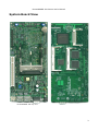
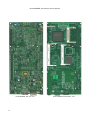
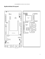
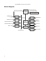
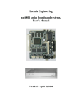
RouterBOARD 200 Series
User's Manual
Rev. Q (22-Nov-2005)
Copyright
Copyright © 2003-2005 MikroTikls SIA. This manual contains information protected by copyright law. No
part of it may be reproduced or transmitted in any form without prior written permission from the
copyright holder.
Trademarks
RouterBOARD, RouterOS, RouterBIOS and MikroTik are trademarks of MikroTikls SIA. All trademarks and
registered trademarks appearing in this manual are the property of their respective holders.
Limited Warranty
Hardware. MikroTikls SIA warrants all RouterBOARD 200 series equipment for the term of one year from
the shipping date to be free of defects in materials and workmanship under normal use and service. All
parts will be repaired or replaced with similar or functionally equivalent parts by MikroTikls SIA during the
warranty term, except in case the returned parts have mechanical, electrical or other accidental or
intended damages caused by improper use or due to wind, rain, fire or other acts of nature.
Parts (or systems) must be shipped pre-paid to our facility in Riga, Latvia. All items must have a Return
Material Authorization (RMA) which you can get by contacting us via email, telephone or fax. RMA must
be printed, signed, and enclosed with the shipment, also the RMA number must be written on the
package itself. Parts sent without following the proper procedure will be treated as those not to be
repaired or replaced due to the above mentioned conditions. Items proved to be free of defects in our lab
will be returned to the customer at the customer's expense. Those that do meet the warranty repair
requirements will be repaired or replaced, and returned to the customer's location at our expense,
extending the warranty term for the time the items are being shipped to and from our facility and
replaced or repaired.
Manual. This manual is provided “as is” without a warranty of any kind, expressed or implied, including,
but not limited to, the implied warranty of merchantability and fitness for a particular purpose. The
manufacturer has made every effort to ensure the accuracy of the contents of this manual, however, it is
possible that it may contain technical inaccuracies, typographical or other errors. No liability is assumed
for any inaccuracy found in this publication, nor for direct or indirect, incidental, consequential or other
damages that may result from such an inaccuracy, including, but not limited to, loss of data or profits.
Caution
To avoid damage of the system, use the correct DC input voltage range.
RouterBOARD 200 Series User's Manual
Table of Contents
Copyright..........................................................................................................................1
Trademarks.......................................................................................................................1
Limited Warranty................................................................................................................1
Caution.............................................................................................................................1
System Board View.....................................................................................................................3
System Board Layout..................................................................................................................5
Block Diagram............................................................................................................................6
Specifications.............................................................................................................................7
Hardware Guide..........................................................................................................................8
Memory and Storage Devices...............................................................................................8
SoDIMM Memory.......................................................................................................8
CompactFlash Interface..............................................................................................8
44 pin 2.5'' ATA Interface............................................................................................8
Extension Slots..................................................................................................................8
PCI Slot (RouterBOARD 230 only)................................................................................8
MiniPCI Slot..............................................................................................................8
PCMCIA Extension Slots (RouterBOARD 230 only)...........................................................8
Input/Output Ports.............................................................................................................9
LAN1 Port with PoE....................................................................................................9
LAN2 Port (RouterBOARD 230 only)..............................................................................9
USB Port (RouterBOARD 230 only)...............................................................................9
GPIO Header.............................................................................................................9
ACCESS.bus..............................................................................................................9
Intrusion Detection – J16............................................................................................9
LCD Out Header........................................................................................................9
LPC Connector...........................................................................................................9
DB9 Serial Port..........................................................................................................9
LEDs...............................................................................................................................10
User LEDs – LED1, LED2, LED3, LED4.........................................................................10
MiniUPS LED – LED5.................................................................................................10
Power LED – LED6....................................................................................................10
CMOS Battery..................................................................................................................10
User's Guide.............................................................................................................................10
Assembling the Hardware..................................................................................................10
Powering.........................................................................................................................10
Power Consumption..................................................................................................11
Booting options................................................................................................................11
Internal Storage Device............................................................................................11
EtherBoot Protocol...................................................................................................11
Operating System Support.................................................................................................11
System Architecture.................................................................................................11
MikroTik RouterOS...................................................................................................12
Linux......................................................................................................................12
OpenBSD................................................................................................................12
FreeBSD.................................................................................................................12
DOS.......................................................................................................................12
RouterBIOS..............................................................................................................................12
BIOS License...................................................................................................................13
Boot Errors......................................................................................................................13
BIOS Configuration...........................................................................................................13
Configurable Options................................................................................................14
How to choose PCI Back-off value...............................................................................14
BIOS Upgrading...............................................................................................................15
Appendix.................................................................................................................................16
Connector Index...............................................................................................................16
Jumper Index...................................................................................................................19
Ethernet Cables................................................................................................................19
Serial Console (Null-modem) Cable.....................................................................................19
2
RouterBOARD 200 Series User's Manual
System Board View
RouterBOARD 230 top view
RouterBOARD 230 bottom view
3
RouterBOARD 200 Series User's Manual
RouterBOARD 220 top view
4
RouterBOARD 220 bottom view
RouterBOARD 200 Series User's Manual
System Board Layout
Top view
Bottom view
5
RouterBOARD 200 Series User's Manual
Block Diagram
48V Power over Ethernet
100BaseTX port
w. PoE
Ethernet
Controller
100BaseTX port
Ethernet
Controller
PCMCIA/CardBUS slot
PCMCIA/CardBUS slot
USB 1.0 port
CardBUS
Controller
Power
Supply
CPU
USB
Controller
PCI/miniPCI slot
6
PCI Bus
Controller
20-56V power jack
20-56V power header
MiniUPS Daughterboard
Memory
Controller
SoDIMM slot
IDE
Controller
IDE/CF
connector
UART
Serial port
GPIO
Controller
GPIO pins
LCD
Controller
LCD header
RouterBOARD 200 Series User's Manual
Specifications
RouterBOARD 220
CPU
RouterBOARD 230
233MHz or 266MHz NSC SC1100 CPU (Intel Pentium MMX architecture)
SoDIMM (up to 512MBytes SDRAM; only accepts standard SoDIMM size; some
PC66 modules will not work)
Memory slot
BIOS
2Mbit Flash BIOS
Hard drive
connectors
CompactFlash type I/II (also supports IBM/Hitachi Microdrive)
44-pin boxhead ATA/IDE connector (for 2.5'' ATA drives)
One NSC DP83816 10/100 Mbps Fast
Ethernet port
Ethernet
MiniPCI slot
Two NSC DP83816 10/100 Mbps Fast
Ethernet ports
One MiniPCI Type IIIA/IIIB slot
PCI slot
PCMCIA slot
Serial port
No PCI
One PCI 2.1 slot with universal
powering (+/-12V, +5V, +3.3V)
No PCMCIA/CardBUS
Two PCMCIA/CardBUS slots
One DB9 RS-232C asynchronous serial port
USB port
No USB
LEDs
One USB 1.0 port
Power, MiniUPS, 4 user LEDs
LCD connector
Parallel LCD header
Temperature
sensors
CPU area, PCI area, LM87 health monitor chip area
Voltage monitor
Intrusion detector
Watchdog
CPU core, +3.3V, +5V, +12V voltage monitoring
Hardware Intrusion Detection header
Two independent watchdog controllers
GPIO
Header for 6 GPIO
ACCESS.bus (I O)
SCL and SDA header
2
Speaker
mini PC-Speaker
IEEE802.3af Power over Ethernet: 48V DC
Power options
Power output
Dimensions
Weight
Temperature
Humidity
Onboard power jack/header: 20 to 56V DC, -20 to -56V DC
(including -48V DC telecom power)
3.3V DC out header
5V DC 400mA (2W) out header with RPM control
10.5 cm x 21.5 cm (4.13 in x 8.46 in)
143g (5.0 oz)
209g (7.4 oz)
Operational: -20°C to +70°C (-4°F to 158°F)
Operational: 70% relative humidity (non-condensing)
3.8-4.4W without extension cards. Maximal – 15W with base voltage 5V:
Power consumption
+12V: 100mA (1.2W)
-12V: 100mA (1.2W)
+5V: 3A (15W)
+3.3V: 1.2A (4W)
7
RouterBOARD 200 Series User's Manual
Hardware Guide
Memory and Storage Devices
SoDIMM Memory
You can use any standard-sized SoDIMM PC100 or PC133 SDRAM memory modules. The PC66 modules,
which do not accept timing frequency more than 66MHz might not work reliably on RouterBOARD 200
series boards, so use of these modules is not recommended. The RouterBIOS automatically adjusts the
timing parameters of an inserted module to its maximal values.
There are some SoDIMM modules that violate the maximal hight dimension defined by the SoDIMM
standard. For example, some 512MB SDRAM modules are about two times higher than the standard
allows. These modules can not be used in the RouterBOARD 200 series computers.
CompactFlash Interface
You can use any CompactFlash Type I or II cards, as well as IBM/Hitachi Microdrive hard drives. JP2
jumper may be used to choose whether the inserted storage device will be ATA Master or Slave device.
Warning! The RouterBOARD 200
CompactFlash/Microdrive devices.
series
boards
do
not
support
hot
insert
of
44 pin 2.5'' ATA Interface
You can use any ATA (IDE) hard drive with 44 pin interface. Generally, 2.5'' hard drives for notebooks
have this interface. Note that you can not connect a standard ATA drive to the RouterBOARD as all
standard ATA hard drives require +12V, but the 44 pin connector only supplies +5V and -5V.
Extension Slots
PCI Slot (RouterBOARD 230 only)
PCI v.2.1 slot with universal powering is compatible with all PCI expansion cards available on the market.
Supplied power:
+12V:
-12V:
5V:
3.3V:
100mA (1.2W)
100mA (1.2W)
3A (15W)
1.2A (4W)
MiniPCI Slot
MiniPCI Type IIIA slot has 3.3V and 5V power signaling with the same output power as PCI connector.
This slot also accepts MiniPCI Type IIIB standard cards.
Note that only AR5212 and newer Atheros MAC chips are stable with RouterBOARD 230, if connected
with a multiport MiniPCI-to-PCI adapter (such as RouterBOARD 14 four-port MiniPCI-to-PCI adapter). This
note only applies to the RouterBOARD 200 platform with multiple Atheros-based cards.
Warning! Do not install PCI and MiniPCI adapters simultaneously. This configuration will not
work and may damage equipment.
PCMCIA Extension Slots (RouterBOARD 230 only)
The RouterBOARD 230 series has two independent PCMCIA/CardBUS slots controlled by Texas
Instruments PCI1250 chip with serialized IRQ (SERIRQ).
8
RouterBOARD 200 Series User's Manual
Input/Output Ports
LAN1 Port with PoE
This Fast Ethernet port is recognized as first LAN interface in most OSs. If is fully compatible with
IEEE802.3af Power over Ethernet standard and accepts 48V input voltage. To use PoE power option, both
JP4 and JP5 must be switched to the 3-2 position.
The RouterBOARD 51 power injector may be used to power the board with up to 150m (492 ft) long
Ethernet cable.
See Connector Index for pinout of the standard cable required for PoE. All cables made to EIA/TIA
568A/B cable specifications will work correctly with PoE. Note that this is a standard host Ethernet port
and if it is required to connect to another host, then a cross-over cable should be used. Note that the
IEEE Ethernet standard requires a minimum 2m long cable (6.5 foot).
LAN2 Port (RouterBOARD 230 only)
The second Fast Ethernet port does not have PoE power option and thus is used only as a separate
Ethernet port. Note that this is a standard host Ethernet port and if it is required to connect to another
host, then a cross-over cable should be used. Note that the IEEE Ethernet standard requires a minimum
2m long cable (6.5 foot).
USB Port (RouterBOARD 230 only)
The USB port is fully compliant with USB 1.0 standard. Booting from USB floppies, USB FlashCards or
other USB drives currently is not supported.
GPIO Header
General Purpose Input/Output (GPIO) header is a set of six user programmable input and/or output
interfaces. Sample code is given in the RouterBOARD 200 SDK.
ACCESS.bus
ACCESS.bus is a two-wire synchronous serial interface compatible with Intel's SMBus and Philips' I2O. The
ACCESS.bus allows bidirectional communication with a wide range of low-cost devices and memories.
Sample code is given in the RouterBOARD 200 SDK.
Intrusion Detection – J16
This is programmable jumper that may be found useful for intrusion detection, or, for example, as a serial
console reset switch. Sample code is given in the RouterBOARD 200 SDK.
LCD Out Header
LCD output header is used to connect parallel LCD devices. Supports LCDs sold by MikroTik. Sample code
is given in the RouterBOARD 200 SDK.
LPC Connector
Low Pin Count (LPC) interface is based on Intel Low Pin Count Interface specification, revision 1.0. It
provides all required signals as well as two optional.
DB9 Serial Port
The RS232C standard male DB9 asynchronous serial port may be used for initial configuration. TxD (pin
3) of this port has -12V DC power when idle, and DTR (pin 4) of this port always has +12V DC power (all
voltages given when not loaded).
9
RouterBOARD 200 Series User's Manual
LEDs
User LEDs – LED1, LED2, LED3, LED4
User LEDs may be programmed at user's option. See RouterBOARD SDK for more details.
MiniUPS LED – LED5
LED is lit when the board is powered from MiniUPS.
Power LED – LED6
LED is on when the board is powered
CMOS Battery
The RouterBOARD can use CR1620 Lithium Coin Battery for preserving the BIOS configuration stored in
CMOS, and also for powering real-time clock (RTC) while off the utility power. This configuration and RTC
may be reset by switching JP3 to the 2-3 position shortly.
User's Guide
Assembling the Hardware
First to use the board:
● Configure jumpers. The board should have 6 jumpers already set in some positions. The Jumper
Index chapter of this manual describes all possible jumper positions
● Insert SoDIMM memory module. Use standard-sized PC100 or PC133 SoDIMM SDRAM modules
● Connect boot device (optional as you may boot the RouterBOARD from network)
● Install PCI, MiniPCI, PCMCIA cards. Note that you may not use both PCI and MiniPCI cards
simultaneously
● Install the board in a case
● Connect other peripherals and cables. Note that the IEEE Ethernet standard requires a minimum
2m long cable (6.5 foot).
You can also order an assembled system with RouterBOARD, memory module and extension cards of your
choice already installed in a case.
Powering
Power options:
● Power jack/header:
20V to 56V DC
-20V to -56V DC (including -48V telecom power)
● IEEE802.3af Power over Ethernet (PoE):
48V DC
RouterBOARD 200 series boards are equipped with a reliable 15W power supply that accepts a wide
range of input voltage. The board has a power jack (5.5mm outside and 2mm inside diameter, female,
pin positive plug) and a power header for input voltage of 20V to 56V DC. To use the power jack/header,
both JP4 and JP5 must be switched to the 1-2 position.
Note that to power the board from -48V (telecom power wires), connect GND power wire to the positive
contact of the board, and -48V wire to the negative contact. Positive contact is the center pin in the
power jack, and the nearest to the power jack square (◘) contact on the J12 power header (there is a
small '+' sign near it).
10
RouterBOARD 200 Series User's Manual
RouterBOARD 200 series are also compliant with IEEE802.3af Power over Ethernet standard and accept
48V powering over up to 150m (492 ft) long Ethernet cable. To use this option, both JP4 and JP5 must
be switched to the 2-3 position.
Power Consumption
Supplied power:
+12V:
-12V:
5V:
3.3V:
100mA (1.2W)
100mA (1.2W)
3A (15W)
1.2A (4W)
Power consumption (tested with 48V power supply):
Empty board: 77mA (3.7W)
Board with 64Mb RAM: 78mA (3.8W)
Board with 64Mb RAM and CF storage: 80..90mA (4..4.4W)
Board with 64Mb RAM, CF storage and 2 PCMCIA cards: 100mA (4.8W)
Board with 64Mb RAM, CF storage, 2 PCMCIA cards and a MiniPCI card: 110mA (5.3W)
Board with 64Mb RAM, CF storage, 2 PCMCIA cards and a MiniPCI card, full load: 130..140mA (6.3..6.8W)
Booting options
First, RouterBIOS is started. It displays some useful information on the onboard RS232C asynchronous
serial port, which is set to 9600bit/s, 8 data bits, 1 stop bit, no parity, hardware (RTS/CTS) flow control
by default. The BIOS may be configured to boot the system from an internal storage device, and/or using
EtherBoot protocol. See the respective section of this manual for how to configure booting sequence and
other BIOS parameters.
Internal Storage Device
The RouterBOARD may be started from an internally connected storage device, such as CompactFlash
module, Microdrive hard drive or ATA drive, that is recognized as ATA Master device.
EtherBoot Protocol
EtherBoot protocol allows you to boot the RouterBOARD 200 series computer from an image stored on a
TFTP server. EtherBoot is a protocol very similar to the well-known PXE. It uses BOOTP (DHCP) protocol
to get a valid IP address, and TFTP protocol to download an executable (ELF) image to boot from (the
server's IP address and the image name must be sent by the BOOTP server). See www.etherboot.org for
more information an protocol details.
To boot the RouterBOARD computer with EtherBoot protocol you need the following:
● An ELF image for BIOS to boot from (for example, you can create an ELF image from Linux kernel
and INITRD image using mkelfImage utility)
● A TFTP server which to download the image from
● A BOOTP/DHCP server (may be installed on the same PC as the TFTP server) to give an IP address,
TFTP server address and boot image name
See the RouterBIOS section on how to configure BIOS to boot using EtherBoot protocol. You can also
press [Ctrl]+[E] while the BIOS is checking memory or waiting for a key combination to force EtherBoot
mode.
Note that you must connect the RouterBOARD you want to boot, and the BOOTP and TFTP servers to the
same broadcast domain (i.e., there must not be any routers between them).
Operating System Support
System Architecture
RouterBOARD 200 series embedded boards are fully compatible with the standard IA32 PC architecture
11
RouterBOARD 200 Series User's Manual
(also known as x86 or as i386) with PCI bus.
CPU. RouterBOARD 200 series has the National Semiconductor Geode SC1100 integrated processor that
is binary compatible with Intel Pentium MMX processors. When compiling programs, you can specify 586
machine architecture with MMX command extensions (this is usually called “Pentium MMX”) to get best
performance. You can also use any programs compiled for i8086, i386, i486 or Pentium instruction sets.
Ethernet. RouterBOARD 200 series has one or two onboard Ethernet ports with National Semiconductor
DP83816 controllers. Linux 2.4 and up and the latest BSD systems have the driver for this chip in the
kernel. The driver for Linux 2.2 is downloadable from www.routerboard.com.
USB. RouterBOARD 230 has a standard OHCI compatible USB controller.
PCMCIA. RouterBOARD 230 has a generic dual-port Texas Instruments PCI1520 PCMCIA/CardBUS
controller, which is supported by Linux yenta_socket driver. The controller chip has serialized IRQ
(SERIRQ) hardwired to IRQ 11. The RouterBIOS writes this information to the PCI configuration space
registers. The Linux v2.4 kernel PCMCIA/CardBUS driver automatically finds this without any special
settings. Other card service software that does not use the PCI configuration space registers may require
special settings or require that IRQ 11 be configured manually.
The RouterBOARD SDK describes programming LEDs, Watchdog, ACCESS.bus and GPIO.
MikroTik RouterOS
MikroTik RouterOS (starting from version 2.7) is fully compatible with RouterBOARD 200 series
embedded boards.
No additional patches required.
Linux
RouterBIOS is able to boot LILO and GRUB Linux loaders. Linux kernels 2.2, 2.4 and 2.6 were tested.
No additional patches required.
OpenBSD
RouterBIOS is able to boot OpenBSD (version 3.4 was tested).
No additional patches required.
FreeBSD
RouterBIOS is able to boot FreeBSD (versions 4.9 and 5.1 were tested).
It is recommended to patch the FreeBSD kernel. You can download patches from www.routerboard.com.
DOS
RouterBIOS is able to boot DOS (MS DOS 6.22 was tested)
Note that as there are no standard USB keyboard drivers for DOS, you might want to use only serial
console, redirecting video output to the serial port (in BIOS, enable parameter vga-to-serial)
RouterBIOS
RouterBIOS provides minimal functionality to boot an Operating System. It supports PCI video cards as
well as serial console via the onboard serial port at the boot time. The BIOS supports booting from
CompactFlash, IBM MicroDrive, ATA drive (no booting from external devices like PCI or USB is currently
supported) and from a network server (using EtherBoot protocol).
Supported OSs:
● RouterOS starting with version 2.7
● Linux
● OpenBSD
12
RouterBOARD 200 Series User's Manual
● FreeBSD
● NetBSD
● DOS
BIOS License
The RouterBIOS uses GNU/GPL LinuxBIOS, Etherboot, and ADLO. To get a CD with the corresponding
source code for the GNU/GPL covered programs in RouterBIOS, wire transfer $45 to MikroTikls SIA,
Pernavas 46, Riga, LV-1009, Latvia. Please contact MikroTikls SIA ([email protected]) for our current
account information and wire transfer instructions. Offer valid until 2010.
Boot Errors
After power-on, all user LEDs (LEDs 1 to 4) are switched on for a short time (to determine that all LEDs
are working). If there are errors happened during the BIOS initialization, an error code is displayed with
user LEDs (note that if LED5 is on, then there is a serious hardware damage, and RouterBOARD may not
be used anymore):
LED2 is on – no RAM detected
LED1 and LED2 are on – testing of the 1st megabyte of RAM failed
BIOS Configuration
BIOS parameters may be configured through the onboard RS232C asynchronous serial interface. To
connect to it, use a standard null-modem cable (pin-out is given in the Appendix). By default, the port is
set to 9600bit/s, 8 data bits, 1 stop bit, no parity, hardware (RTS/CTS) flow control.
To enter the BIOS configuration screen, press any key (or only [Delete] key (or [Backspace] key – see
the note for the respective configurable option), depending on the actual configuration) just after the
BIOS is asking for it:
RouterBIOS v1.3.0 MikroTik (tm) 2003-2004
RouterBOARD 220 (CPU revision B1)
CPU frequency: 233 MHz
Memory size: 64 MB
Press any key within 1 second to enter setup.
RouterBIOS v1.3.0
What do you want to configure?
d - boot delay
k - boot key
s - serial console
l - debug level
o - boot device
b - beep on boot
v - vga to serial
t - ata translation
p - memory settings
m - memory test
u - cpu mode
f - pci back-off
r - reset configuration
g - bios upgrade through serial port
c - bios license information
x - exit setup
your choice:
To select a menu point, press the key written at the beginning of this line. Pressing [Enter] selects the
13
RouterBOARD 200 Series User's Manual
option marked with '*'.
Configurable Options
boot delay
default).
- how much time to wait for a key stroke while booting (0..10 seconds; 1 second by
boot key - which key will cause the BIOS to enter configuration mode during boot delay (any key |
<Delete> key only; any key by default). Note that in some serial terminal programs, it is impossible to
use the [Delete] key to enter the setup – in this case it might be possible to do this with the [Backspace]
key.
serial console – to configure initial serial console bitrate (1200 | 2400 | 4800 | 9600 | 19200 | 38400 |
57600 | 115200; 9600 bps by default).
debug level – BIOS debug level (none | low | high; low by default). If set to high, the BIOS displays
much information about the boot process, that may be used for debugging.
boot device – initial boot device(s) (IDE | Etherboot | Etherboot (timeout 15s), IDE | Etherboot (timeout
1m), IDE | Etherboot (timeout 5m), IDE | Etherboot (timeout 15s), IDE | Etherboot (timeout 30m), IDE |
IDE, try Etherboot first on next boot (15s) | IDE, try Etherboot first on next boot (1m) | IDE, try
Etherboot first on next boot (5m) | IDE, try Etherboot first on next boot (30m); IDE default).
beep on boot – whether to beep during boot procedure (yes | no; yes by default).
vga to serial – whether to map VGA output to the serial console (yes | no; yes by default). Should be
enabled if working via serial terminal.
ata translation – configures ATA block translation mode (auto | none | lba | large; auto by default).
Should be left by default in most cases. Only if the installed OS is configured to use other translation
methods, you may have to adjust this parameter manually.
memory settings – SDRAM memory speed (optimal | fail-safe; auto by default). When set to optimal,
the BIOS tries to determine the correct memory settings by itself. Set to fail-safe if you are experiencing
memory-related errors (generally random, not reproducible errors and freezes). In this case, minimal
timing parameters are used, so most memory modules will work reliably.
memory test – whether to test all the RAM during boot procedure (yes | no; no by default). If set to no
then the first megabyte of RAM is tested anyway. Enabling this option may cause longer boot process.
cpu mode – whether to enter CPU suspend mode on HTL instruction (power save | regular; power save
by default). Most OSs use HLT instruction during CPU idle cycle. When CPU is in suspend mode, it
consumes less power, but in low-temperature conditions (below 0°C) it is recommended to choose
regular mode, so that overall system temperature would be higher.
pci back-off – When enabled, external PCI masters can access system memory even when a CPU cycle
has been retried (enabled | disabled; enabled by default). If you are experiencing uncommon problems
with PCI/PCMCIA/CardBUS interfaces (including RouterBOARD is rebooting or hanging up once in a
while), try to disable this.
reset configuration – whether to reset all the BIOS settings to their respective default values (yes | no;
no by default).
bios upgrade through serial port – receive a new BIOS image using XModem protocol
bios license information – prints the BIOS license agreement.
How to choose PCI Back-off value
Common practice, how to choose the pci back-off parameter value:
● Keep enabled if you are using Atheros PCMCIA cards
● Enable on newer RouterBOARD 200 boards (with 266MHz CPU clock) with Atheros MiniPCI cards in
RouterBOARD 14 (4-port MiniPCI-PCI) adapter
● Disable on older RouterBOARD 200 boards (with 233MHz CPU clock) with Atheros MiniPCI cards in
RouterBOARD 14 (4-port MiniPCI-PCI) adapter
14
RouterBOARD 200 Series User's Manual
● Disable it if you are using newer RouterBOARD 200 boards (with 266MHz CPU clock) with external
PCI Ethernet cards.
● Enable for all boards produced since May 2003, there should be no issues with any PCI devices.
All of these practices has been defined experimentally, so they may or may not apply to your particular
case.
BIOS Upgrading
The BIOS is needed to recognize all the hardware and boot the system up. Newer BIOS versions might
have support for more hardware, so it's generally a good idea to upgrade the BIOS once a newer version
is available. You can upgrade the BIOS through the onboard serial port using XModem protocol (programs
available for all major OSs). For example, you can use HyperTerminal for Windows or Minicom for Linux to
upload the BIOS. The BIOS image is available for download on www.routerboard.com.
If you are using a Microsoft Windows series operating system, you can use the remote upgrading
application available on www.routerboard.com. This program uses EtherBoot protocol to send the image
to the RouterBOARD. See the respective manual section on how to use EtherBoot client on the
RouterBOARD 200 series computers.
You can download from www.routerboard.com a special disk image (this image is a standard raw image
you can write on a CompactFlash or on an ATA drive with a program like PhysDiskWrite for Windows or dd
for UNIX/Linux), which You can use to boot the RouterBOARD from. This program will upgrade the BIOS
to the latest version.
The BIOS upgrading is supported also from MikroTik RouterOS. The procedure is described in the
MikroTik RouterOS manual.
15
RouterBOARD 200 Series User's Manual
Appendix
Connector Index
J1
PCI female slot
J2
SoDIMM slot
J3
RS232C male DB9 port
J4
LCD male header
1 VCC +5V
2 GND
3 RS (Register Select, AFDX)
4 Contrast adjust (controlled)
5 E (Enable signal, INITX)
6 R/W (Data read/write or SLINX)
7 Data 1
8 Data 0
9 Data 3
10 Data 2
11 Data 5
12 Data 4
13 Data 7
14 Data 6
15 Backlit GND (controlled)
16 Backlit VCC +5V
J5
44-pin mini IDE connector for 2.5'' IDE HDD drives
J6
CompactFlash slot
J7
RJ45 Fast Ethernet 100Base-TX port with optional IEEE802.3af PoE extension
1 TX+ Data
2 TX- Data
3 RX+ Data
6 RX- Data
J8
USB Type A connector
J9
RJ45 Fast Ethernet 100Base-TX port
1 TX+ Data
2 TX- Data
3 RX+ Data
6 RX- Data
J10
16
Dual PCMCIA/Cardbus slot
RouterBOARD 200 Series User's Manual
J11
5V 400mA (2W) Fan output (male header)
1 GND
2 VCC +5V
3 Fan speed control
J12
Power header (positive contact is a square (◘) contact with a small '+' sign near it)
J13
Power jack (positive contact is the central pin)
J14
Low Pin Count (LPC) connector
1 VCC +3.3V
2 PCICLK
3 GND
4 LFRAME
5 LPC_ROM
6 LAD3
7 LAD2
8 LAD1
9 LAD0
10 RESETX
J15
MiniPCI Type IIIA connector
J16
Intrusion Detection jumper
J17
MiniUPS daugterboard female header (proprietary pinout)
1,2 +5V DC 0.8A output; or power input for the board, +5V ±5% DC
3,4 Ground
5 Ext. power state (0 – no power, 3.8V – power ok), connected to GPWIO0 CPU signal
6 Battery low signal, associated with GPWIO1 CPU signal
7 UPS control, read from JP6 (0 – 2-3 position; 1 – 1-2 position)
8 External RouterBOARD power switch (set in “1” to switch the board off)
J18
3.3V output (positive pin is marked with a small '+' sign)
J19
GPIO header
1 VCC +3.3V
2 GND
3 SDA1 (ACCESS.bus Port 1 Serial Data Line)
4 SCL1 (ACCESS.bus Port 1 Serial Clock Line)
5 GPIO 47
6 GPIO 41
7 GPIO 40
8 GPIO 38
9 GPIO 20
10 GPIO 18
17
RouterBOARD 200 Series User's Manual
J20
IEEE1149.1 Boundary Scan Architecture (JTAG) connector
1 TDO (Test Data Output)
2 TDI (Test Data Input)
3 TCK (Test Clock)
4 TMS (Test Mode Select)
5 TRST# (JTAG Test Reset)
18
RouterBOARD 200 Series User's Manual
Jumper Index
JP1
JP2
JP3
JP4
JP5
JP6
Reset
Open
Normal operation
Close
Force immediate reboot
CompactFlash ATA Master/Slave select
Open
CompactFlash is ATA Slave device
Close
CompactFlash is ATA Master device
Clear CMOS Data
1-2
Normal operation
2-3
Clear CMOS data
Power source select
1-2
External powering (jack or header)
2-3
IEEE802.3af Power over Ethernet
MiniUPS select
1-2
Use only utility power without MiniUPS (default; disables MiniUPS)
2-3
Use MiniUPS daugterboard
Ethernet Cables
RJ45
Pin
Color
Function RJ45 pin for Straight cable RJ45 pin for Crossover cable
(MDI, EIA/TIA568A)
(MDI-X, EIA/TIA568B)
1
Green
TX+ Data
1
3
2
Green/White
TX- Data
2
6
3
Orange
RX+ Data
3
1
4
Blue
-
4
4
5
Blue/White
-
5
5
6
2
6
Orange/White RX- Data
7
Brown
-
7
7
8
Brown/White
-
8
8
Serial Console (Null-modem) Cable
DB9f Function DB9f DB25f
1+6
CD+DSR
4
20
2
RxD
3
2
3
TxD
2
3
4
DTR
1+6
6+8
5
GND
5
7
7
RTS
8
5
8
CTS
7
4
19