1
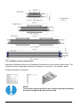
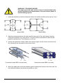
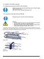
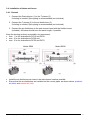
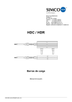
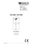
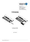
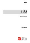
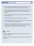
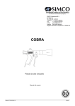
SIMCO (Nederland) B.V. Postbus 71 7240 AB Lochem, The Netherlands Telephone +31-(0)573-288333 Fax +31-(0)573-257319 E-mail [email protected] Internet http://www.simco-ion.nl Apeldoorn trade register no. 08046136 CleanION web cleaner heads model SE60-1, SE60-2, SE60-3 and SE80 Instructions for installation and operation CleanION SE_UM_9752435003_GB_V0_1 Original English manual CONTENTS 1. Health and safety requirements ............................................................................................... 3 1.1. General .............................................................................................................................. 3 1.2. Important notes.................................................................................................................. 3 1.3. Personal requirements ...................................................................................................... 3 1.4. Signs ................................................................................................................................. 4 1.5. Machine mark .................................................................................................................... 4 1.6. Redesigning ...................................................................................................................... 4 1.7. Dismantling and transportation .......................................................................................... 4 1.8. Manufacturer ..................................................................................................................... 5 2. General .................................................................................................................................... 5 2.1. Description of function ....................................................................................................... 5 2.2 Proper use .......................................................................................................................... 5 2.3. Improper use ..................................................................................................................... 6 2.4. Noise ................................................................................................................................. 6 3. Installation ................................................................................................................................ 6 3.1. Requirements regarding placement................................................................................... 6 3.1.1. How much space is required ....................................................................................... 6 3.1.2. Placement of the web cleaner head ............................................................................ 6 3.2. Installation of web cleaner head ........................................................................................ 8 3.3. Installation of antistatic equipment................................................................................... 10 3.3.1. Mounting of the power unit (5kV) for anti-static bars ................................................. 10 3.3.2. Connection of anti-static bars, type MaxION ............................................................. 10 3.4. Installation of tubes and hoses ........................................................................................ 11 3.4.1. General ..................................................................................................................... 11 4. Operation and maintenance of the web cleaner ..................................................................... 12 4.1. Instructions and adjustment ............................................................................................. 12 4.2. Personal protective equipment ........................................................................................ 13 4.3. Maintenance and inspection ............................................................................................ 13 4.3.1. The web cleaner head .............................................................................................. 13 4.3.2. Active anti-static equipment ...................................................................................... 13 5. Spare parts ............................................................................................................................ 14 6. Troubleshooting ..................................................................................................................... 14 CleanION SE_UM_9752435003_GB_V0_1 2 1. Health and safety requirements 1.1. General This Manual comprises instructions for installation and operation. Study this manual carefully and make sure that this manual always is available to all personnel involved in installation and operation of the equipment. The following safety instructions concern all work on this equipment as well in the area close to the equipment. Local restrictions concerning this specific factory ought to be taken in consideration. 1.2. Important notes It is mandatory that: this manual and other applicable documents are preserved during the hole life span of the equipment. this manual and other applicable documents are constituent of the equipment. further complementary additions or changes performed or approved by SIMCO (Nederland) B.V., must be completed/added accordingly in the manuals concerned. this manual must be sent forward to other owners or users of the equipment. the CE-mark does not cover components not approved by SIMCO (Nederland) B.V., used in redesigning or rebuilding of the equipment. SIMCO (Nederland) B.V. can not be held responsible for not covering any internal or local regulations, electrical or mechanical. 1.3. Personal requirements In order to avoid personnel injury and damages, operating shall be done according to the manufacturer’s manual. Operating personnel may only handle parts of the equipment for which they are instructed. NOTE! Electricians should be certified according to local regulations and have experience of similar type of installations, proven skills in reading and working from drawings and cable list, and knowledge of local safety regarding power and automation. NOTE! In general: Switch off the equipment at the main power and padlock the Main Switch before carrying out maintenance or repair work. CleanION SE_UM_9752435003_GB_V0_1 3 1.4. Signs Signs of Danger, Warning, Caution and Note have the following significance: DANGER! Neglecting this information can result in danger of life or serious personnel injury. WARNING! Disregarding this information can result in minor personnel injuries or damage to the equipment. NOTE! Information requiring special attention 1.5. Machine mark This equipment is CE-marked, see figure below, ensuring that the equipment is designed, manufactured and documented in conformity with the Machine Directive 2006/42/EC. 1.6. Redesigning The CE-mark does not cover components not approved by the manufacturer, used in redesigning or rebuilding the equipment. Warning signs and the CE-marking sign shall be placed fully visible. If part of the equipment with a sign is being replaced, a new sign must be attached at the same place. Damaged signs and CE-marks must be replaced promptly. If the equipment is being rebuilt, it is of utmost importance that this manual is promptly completed/adjusted with the necessary photos, illustrations and text showing the changes made. 1.7. Dismantling and transportation Dismantling and transportation of this equipment may only be performed by authorized personnel. CleanION SE_UM_9752435003_GB_V0_1 4 1.8. Manufacturer SIMCO (Nederland) B.V. Postbus 71 NL-7240 AB Lochem Telefoon + 31-(0)573-288333 Telefax + 31-(0)573-257319 E-mail [email protected] Internet http://www.simco-ion.nl 2. General 2.1. Description of function Dust and loose fibers are removed from a moving web. Turbulent air streams create short wave vibrations in the web that brakes down the boundary layer and shake off dust particles from the surface. The web cleaner head is connected to a Filter-Fan unit (FF unit) by tubes and air hoses. Anti-static equipment, consisting of active ionizers, is installed before and after the web cleaner head in order to lower the static charges to a level where they do not prevent the proper cleaning of the web. The web cleaner head consists of two parts. The upper part of the web cleaner head can be raised by pneumatic cylinders to facilitate the web threading. Those parts of the head which face the web each have two slots aimed at the web. A turbulent air stream blows out of the last slot at an angle towards the web, while the first slot vacuums the swirling dust from the web. Model SE60 Model SE80 WARNING! CRUSHING HAZARD The upper part of the web cleaner must be locked mechanically, during installation and maintenance of the web cleaner head, to avoid crushing injuries. 2.2. Proper use CleanION web cleaner heads may only be used in installations for which they are designed. If used improperly, the function and safety guarantee does not apply. CleanION SE_UM_9752435003_GB_V0_1 5 2.3. Improper use CleanION web cleaner heads must not be used in any other way than what they are designed for. They must not be installed in the proximity of oil or silicone mist. NOTE! The CleanION web cleaner system must not be installed in an explosion hazardous environment. For installation in explosion hazardous environment, certain regulations must be followed, please contact SIMCO (Nederland) B.V. for further information. 2.4. Noise The CleanION web cleaner head has been noise-tested. Sound pressure tests have been conducted. With no web in the head, a sound pressure level of 84 dbA was measured. WARNING! USE EAR PROTECTION Ear protection must be worn when working in the immediate vicinity of the web cleaner head. See “Personal Protective Equipment”. 3. Installation In order for the guarantee regarding mechanical function and safety, the installation instructions must be followed. 3.1. Requirements regarding placement 3.1.1. How much space is required To determine how much space is required for installation and subsequent service and maintenance, see next page. The xxxx-dimension: (the web width, rounded upwards to a multiple of 100) + 20mm. f.e. web width 1140, rounded upwards = 1200, so xxxx = 1200 + 20 = 1220 3.1.2. Placement of the web cleaner head The CleanION web cleaner head must be installed at the right place on the machine for the web cleaner to do its job satisfactorily. The most appropriate placement varies for each type of machine. NOTE! The CleanION web cleaner head must be installed with the curved portion of the profile at the side where the web exits the head. CleanION SE_UM_9752435003_GB_V0_1 6 Below are some general guidelines: Printing machines The CleanION web cleaner head should be installed before, and as close to the first printing unit as possible, if possible between two rollers. The distance should be as short as possible so that airborne dust does not settle on the web. For installations in rotogravure machines, the web cleaner head shall be installed so that no solvent can be sucked into the web cleaner. Slitting machines The CleanION web cleaner head should be installed as close after the slitting blades as possible, so that the dust is removed right at the source. The web should not pass any rollers, which can press the dust from the slitting process into the surface of the web, between the slitting blades and the web cleaner head. Distance between guide rolls The optimal distance from the CleanION web cleaner head to the guide rolls on both sides depends on the web material, the web tension and the web speed. The web cleaner head should be installed as close as possible to the rollers. Note that anti-static equipment must not be installed near conductive materials (roller, infeed guide, etc). NOTE! The web cleaner head must not be installed in the proximity of oil and silicone mist. CleanION SE_UM_9752435003_GB_V0_1 7 All models SE60 Stroke 30 3.2. Installation of web cleaner head Manufacture brackets at the time of installation and fasten the web cleaner head to these. The brackets should be adjustable vertically and sideways, as shown in the example below. Design suggestions of brackets NOTE! The brackets which support the web cleaner head must withstand at least the weight of the web cleaner head. CleanION SE_UM_9752435003_GB_V0_1 8 WARNING! CRUSHING HAZARD The upper part of the web cleaner must be locked mechanically, during installation and maintenance of the web cleaner head, to avoid crushing injuries. 1. Install the brackets so that the distance between the bottom profile and the web is 2 mm. Model SE60 Model SE80 2. Adjust the distance between the web and the lower part of the web cleaner head by moving the brackets or by using shims. The web cleaner head and the web must be parallel in all directions. The tolerance is ±0.5 mm. 3. Connect the pneumatic hoses. Make sure that the upper and the lower connections on the cylinder(s) are connected to the correct hose. Connection model SE60 on both sides Connection model SE80 (one side) 4. When the upper part of the web cleaner head is lowered and rests on the lower part, the free distance between the aluminum profiles is 4 mm. CleanION SE_UM_9752435003_GB_V0_1 9 3.3. Installation of antistatic equipment 3.3.1. Mounting of the power unit (5kV) for anti-static bars Mount the power unit at a place within the reach of the HV cables of the anti static bars. See also the user’s manual of the power unit. 3.3.2. Connection of anti-static bars, type MaxION See also the user’s manual of the anti-static bars. Warning: The anti-static bars must be connected properly to the power unit. The power unit must be earthed properly. Earthing is needed to ensure proper operation of the product and to avoid unpleasant shocks upon contact. Connection of the anti-static equipment: The SE60 web cleaner head is equipped with 4 (2x2) antistatic bars. The high voltage cables are located as shown below and are to be connected to the power unit. See also the instructions for the power unit. Model SE60 Model SE80 CleanION SE_UM_9752435003_GB_V0_1 10 3.4. Installation of tubes and hoses 3.4.1. General 1. Connect the Dustcollector (1) to the T-pieces (2). If ducting is needed, Spiro piping is recommended (not included). 2. Connect the T-pieces (2) to the air distributors (3). If ducting is needed, Spiro piping is recommended (not included). 3. Connect the air distributors to the web cleaner head with the flexible hoses (included). All hoses should have the same length, if possible. Keep the ducting as short as possible, we recommend: max. 5 m for dustcollector DC15 and DC22, max. 10 m for dustcollector DC30 and max. 15 m for dustcollector DC55 and DC75. Model SE60 Model SE80 (2) (2) (3) (1) (3) (1) Install the air distributors as close to the web cleaner head as possible. Ensure that the air distributors are installed on the correct pipes, as shown above, pressure air (blue) and vacuum air (red). CleanION SE_UM_9752435003_GB_V0_1 11 The air distributors have symbols for pressure air and vacuum air, respectively. Pressure air Vacuum air The hoses shall be as straight and short as possible. All hoses should have the same length, if possible. The hoses should be able to follow the upper part of the web cleaner head when it is raised during web threading. NOTE! The hoses must not be bent or squeezed so that the airflow is restricted. The pipes and hoses must be installed correctly, otherwise the web cleaner will not work. 4. Operation and maintenance of the web cleaner Before operating the web cleaner head, the following checks must be done: Check that the air hoses are connected correctly. the compressed air is connected to the web cleaner head. the hand valve is connected correctly. the Pressure/Vacuum gauges are connected to the correct air distributor. 4.1. Instructions and adjustment For the best results with the web cleaner, the amount of blown air and vacuum air should be adjusted for each material and web speed. After each adjustment make sure to tighten the screws on the valve. Fine-tune the relation between blown and vacuum air by adjusting the valve so that the pressure changes approximately 10 mm vp. Run for a while (a few days) and compare the cleaning results and the amount of dust collected. Then select the position on the valve that gives the best cleaning effect. Note or mark the setting on the manometer. CleanION SE_UM_9752435003_GB_V0_1 12 NOTE! An instruction for installation and operation of Simco-Ion Dustcollector model DC15, DC22, DC30, DC55 and DC75 is published in a separate document. 4.2. Personal protective equipment If staff goes close to the dustcollector or the web cleaner head when these are in operation, ear protection must be worn. WARNING! USE EAR PROTECTION Ear protection must be worn when working in the immediate vicinity of the web cleaner system. 4.3. Maintenance and inspection For SIMCO (Nederland) B.V. as a manufacturer to be able to guarantee the function and safety of the web cleaner head, regular inspections/maintenance are required. An appropriate inspection / service interval is 500-800 hours of operation or more often, depending on the amount of ambient dust. 4.3.1. The web cleaner head Blow dust and coarse particles from the slots when necessary, at least twice a year. Apart from that, the web cleaner head does not require any attention. WARNING! CRUSHING HAZARD The upper part of the web cleaner must be locked mechanically, during installation and maintenance of the web cleaner head, to avoid crushing injuries. 4.3.2. Active anti-static equipment For maintenance and inspection of antistatic equipment, see the user’s manual of the power unit and the user’s manual of antistatic bars, read carefully all notes. CleanION SE_UM_9752435003_GB_V0_1 13 5. Spare parts Use only SIMCO (Nederland) B.V. original spare parts. For spare parts, please contact SIMCO (Nederland) B.V. or your nearest SIMCO (Nederland) B.V. distributor, always specify the Simco-Ion item number of the web cleaner system when ordering. The Item number is shown on the type shield of the dustcollector. For dustcollector spare parts see instructions for installation and operation of Simco-Ion Dustcollector model DC15, DC22, DC30, DC55 and DC75. 6. Troubleshooting Check first that the hoses to the web cleaner head are correctly connected to blown and vacuum air, respectively. Problem Probable cause -The web is Too little blown air sucked to the web cleaner head. Too much vacuum air Action Increase the blown air by closing the valve for the blown air. Decrease the vacuum air by opening the valve for the suctioned air. If the above actions do not help, contact SIMCO (Nederland) B.V. or your nearest SIMCO (Nederland) B.V. distributor. CleanION SE_UM_9752435003_GB_V0_1 14 CleanION SE_UM_9752435003_GB_V0_1 15