1
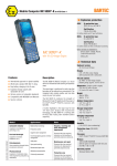
ATEX Version Zone 1 Mobile Computing User Manual MC 9090ex-G MC 9090ex-K Type 17-A119-OG.O/H....... Type 17-A119-OK.O/H....... User Manual Mobile Computer MC 9090ex-G Type 17-A119-0G.0/H……. Mobile Computer MC 9090ex-K Type 17-A119-0K.0/H……. ATEX Version Zone 1 Version 3.00 Document No. 11-A119-7D0001 Status: September, 5th 2007 Technical data subject to change! GmbH Max-Eyth-Straße 16 97980 Bad Mergentheim Germany Phone: +49 7931 597-0 Fax: +49 7931 597-183 Contact: [email protected] Indroduction Before commissioning the devices, please read through the relevant documents carefully. Target group: Experienced and trained specialists acting in compliance with the 99/92/EC directive, IEC 60079-19 and IEC 60079-17. Important note: This user manual contains important information, safety instructions and test certificates that are necessary for perfect functioning when operating and handling the Mobile Computer. If the information and safety instructions for the devices are not observed, its use to the intended purpose in hazardous (potentially explosive) zones can no longer be guaranteed. Device modifications that are not expressly approved by BARTEC may invalidate the operating permit for the respective device. Non-conformance will also rule out claims under guarantee. The warranty will be rendered invalid if the delivered item is harmed because of inappropriate handling, excessive strain, inadequate servicing, abnormal operating conditions or transport damage. Natural wear is also excluded from warranty. BARTEC reserves the right to alter the contents of the document without notice. No guarantee is given for the correctness of the information. In case of doubt the original German version of the safety information will apply because it is not possible to rule out errors in translation or in printing. In the event of a law case, the “General Terms and Conditions“ of the BARTEC Group will apply in addition. If any differences emerge between the contents in the documents from Motorola and those from BARTEC, the information in this Mobile Computer MC 9090ex user manual shall apply. The respective up-to-date versions of data sheets, manuals, certificates and EC Declaration of Conformity may be downloaded from the “Ex Visualisation and Communication Systems“ product page at www.bartec-group.com, or ordered directly from BARTEC GmbH. Information from the Manufacturer SYMBOL/Motorola No licence is granted explicitly or implicitly or by tacit permission or in any other way in the context of a patent right or a patent referring to a combination, a system, a device, a machine, material, a procedure or a process in which products from Symbol could be used. There is merely an implicit licence for devices, electrical systems and subsystems that are contained in Symbol/Motorola products. Documentation This document is available in German and English at present. Visit our web site http://www.bartec-group.com and find out about your special product. Contents 1. Product Description .....................................................................................................................................................1 1.1 General ...........................................................................................................................................................1 1.2 Use..................................................................................................................................................................2 1.3 Advantages .....................................................................................................................................................2 2. Safety Instructions .......................................................................................................................................................3 2.1 Warnings about the Mobile Computers...........................................................................................................3 2.2 Warnings about the battery.............................................................................................................................4 2.3 Warnings about Laser Devices .......................................................................................................................5 2.4 Notes on installation........................................................................................................................................5 2.5 Electromagnetic Fields....................................................................................................................................7 2.5.1 International..................................................................................................................................7 2.5.2 Portable Devices ..........................................................................................................................7 2.5.3 Handheld Devices ........................................................................................................................7 2.6 Health and Safety Recommendations .........................................................................................................8 2.6.1 Ergonomic Recommendations .....................................................................................................8 2.6.2 Vehicle Installation .......................................................................................................................8 2.7 Warnings for Use of Wireless Devices.........................................................................................................9 2.7.1 Safety in Aircraft ...........................................................................................................................9 2.7.2 Pacemakers .................................................................................................................................9 2.7.3 Hearing Aids.................................................................................................................................9 2.7.4 Other Medical Devices .................................................................................................................9 3. Technical Data ............................................................................................................................................................10 3.1 Explosion Protection .....................................................................................................................................10 3.2 General Data.................................................................................................................................................10 3.3 Technical Data Scan Engine and Decode Zone ...........................................................................................12 3.3.1 Scan Engine for Type 17-A119-0GJ0/H...... (Long Range Scan Engine) .................................12 3.3.2 Scan Engine for Type 17-A119-0KA0/H...... (Standard Range Scan Engine)...........................13 3.3.3 Scan Engine for Type 17-A119-0KK0/H...... (Imager) ..............................................................14 3.4 Technical Data - WLAN / WPAN...................................................................................................................15 3.5 Technical Data - Battery................................................................................................................................16 3.6 Product Marking ............................................................................................................................................17 3.6.1 Mobile Computer MC 9090ex ......................................................................................................17 3.6.2 Battery 17-A1Z0-0001 ................................................................................................................17 3.7 Laser Labels..................................................................................................................................................18 3.8 WLAN / Bluetooth..........................................................................................................................................19 3.8.1 Radio Modules ...........................................................................................................................19 3.8.2 Products Equipped with Bluetooth® Wireless Technology ........................................................19 Commissioning...........................................................................................................................................................21 4.1 Mobile Computer...........................................................................................................................................21 4.2 Display ..........................................................................................................................................................21 4.3 Battery...........................................................................................................................................................22 4.3.1 Cradles .......................................................................................................................................22 4.3.2 Charging Station.........................................................................................................................22 4.3.3 Power Supply .............................................................................................................................23 4.3.4 Charging the Battery ..................................................................................................................23 4.4 Installing Battery............................................................................................................................................24 4. Contents 5. Handling ......................................................................................................................................................................25 5.1 MC 9090ex-K Mobile Computer .....................................................................................................................25 5.2 MC 9090ex-G Mobile Computer.....................................................................................................................26 5.3 Battery...........................................................................................................................................................27 5.3.1 Battery Informationen .................................................................................................................27 5.3.2 Charging Processes ...................................................................................................................27 5.3.3 Tips on Optimising the Operating Time......................................................................................29 5.4 Software Settings..........................................................................................................................................29 5.4.1 Changing the Power Settings.....................................................................................................29 5.4.2 Changing the Display Backlight Settings....................................................................................30 5.4.3 WLAN on Windows Mobile 5.0...................................................................................................30 5.4.4 Bluetooth on Windows Mobile 5.0 ..............................................................................................30 5.4.5 Waking the Mobile Computer .....................................................................................................31 5.4.6 Connection with the PC via ActiveSync for OS Windows 98, NT, 2000 and XP........................31 5.4.7 Connection with the PC via Device Center for OS Windows Vista.............................................31 5.5 Booting Mobile Computer..............................................................................................................................32 5.5.1 Windows Mobile 5.0 Devices .....................................................................................................32 5.5.2 Performing a Warm Boot............................................................................................................32 5.5.3 Performing a Cold Boot ..............................................................................................................32 6. Additional Components .............................................................................................................................................34 6.1 Keypad and CD Card....................................................................................................................................34 6.1.1 Keypad with Blue Overlay ..........................................................................................................34 6.1.2 SD Cards....................................................................................................................................34 6.1.3 Removing/Changing the Keypad................................................................................................35 6.1.4 Inserting/Replacing the SD Card................................................................................................37 6.2 Open Case and Holster.................................................................................................................................38 6.2.1 Open Case for MC 9090ex "Version Gun", type 17-A119-0Gx0HJxFA6xx.................................38 6.2.2 Holster for MC 9090ex "Version Brick", type 17-A119-0Kx0HJxFA6xx.......................................39 6.3 Stylus ............................................................................................................................................................40 6.3.1 Stylus for MC 9090ex-K...............................................................................................................40 6.3.2 Stylus for MC 9090ex-G ..............................................................................................................40 6.4 Headset or Other Audio Devices...................................................................................................................40 7. Maintenance................................................................................................................................................................41 7.1 Care of the Battery........................................................................................................................................41 7.2 Cleaning the Battery Contacts ......................................................................................................................41 7.3 Information about Repairs.............................................................................................................................41 8. Additional Information ...............................................................................................................................................42 8.1 Links..............................................................................................................................................................42 8.2 Information around the Explosion Protection ................................................................................................43 8.3 Accessories...................................................................................................................................................45 8.4 Order numbers..............................................................................................................................................47 9. Transport and Shipment ............................................................................................................................................49 Appendix A Certificates Product Description 1. Product Description 1.1 General The MC 9090ex-G and MC 9090ex-K Mobile Computers each form a compact unit for high-standard barcode scanning in hazardous (potentially explosive) areas. The comfortably positioned scan trigger and the ergonomic design of the MC 9090ex device series allow the acquisition of data with one-hand operation. The MC 9090ex device series is available in various versions. MC 9090ex-G MC 9090ex-K Both the MC 9090ex-G Mobile Computer (Gun version) and also the MC 9090ex-K Mobile Computer (Brick version) allow data to be exchanged with the host system in real time. The devices in the innovative MC 9090ex series are powerful hand-held mobile computers that combine the advantages of the Microsoft Pocket PC platform and the strengths of the Intel® XScaleTM PXA270 processor with 624 MHz. They feature a large easy-to-read 1/4 VGA colour display with attractive touchscreen technology. The radio standard used is IEEE 802.11a/b/g (direct sequence). <1> Product Description 1.2 Use The Mobile Computer is a hand-guided electrical device used for the mobile acquisition, processing and radio transmission of data in hazardous areas. The Mobile Computer is used in areas designated for the use of devices from Equipment Group II, Category 2G. It is connected only to operating equipment that satisfies the requirements of Overvoltage Category I. The MC 9090ex series is specially intended for use in the zone 1 hazardous area. It is not allowded to use the MC 9090ex in zone(s) 0 / 20 / 21 / 22. 1.3 Advantages ■ ■ ■ ■ ■ ■ ■ ■ <2> Data access is possible in real time Lithium-ion storage batteries allow maximum operating time between chargings Battery replaceable in Ex area WLAN radio technology IEEE 802.11a/b/g Bluetooth Additional memory with an SD card Different scan engines allow different barcode applications Replaceable keypads in 3 variants Safety Instructions 2. Safety Instructions 2.1 Warnings about the Mobile Computers ■ ■ Take the device out of the hazardous areas before wiping it with a dry cloth or cleaning it! ■ The device may not be opened by the user outside the hazardous area either! The user may not make any alterations to the device. Do not exchange or replace components and do not retrofit any components on internal plug connectors or slots. If components other than those specified are used, the protection against explosions can no longer be assured. Do not open or charge the device and do not exchange any data through the "cradle contacts" on the battery in the hazardous area! Operating the 17-pin data interface (see chapter 3.5 "Technical Data Battery, Article "External Battery Contacts") is only permissible outside the hazardous area and only with devices specified by the manufacturer! Exception: Keypad and SD card (see chapter 6.1 "Keypad and SD Card") ■ Protect the device from impact effects! Do not expose the operating equipment to any caustic/aggressive liquids, vapours or mist! In the event of malfunctioning or damage to the enclosure, take the equipment out of the potentially explosive atmosphere immediately, bring it into a safe area and decommission it by removing the battery! ■ If on account of adverse effects or conditions (e.g. penetration of water, fluids, exposure to temperatures outside the specified range etc.) there is a danger of not being able to operate the equipment safely, switch off the equipment instantly and remove the battery. ■ General statutory regulations or directives on safety at work, accident prevention regulations and environmental protection legislation must be complied with, e.g. Ordinance on industrial health and safety (BetrSichV) or the national ordinances. ■ Ensure safe handling of the equipment during operation by making sure the device in a steady position and the user has sufficient space to move! ■ After use, the equipment must be placed where it will be sheltered from falling objects and out of danger of falling itself. This must also be ensured even if only putting it down for a short time when taking a break from work. <3> Safety Instructions 2.2 <4> ■ When transporting the equipment in vehicles, it must be placed in appropriate compartments or fittings so that it can neither fall off during the drive nor be exposed to extreme vibrations. ■ The rules for hazardous areas (see directive 99/92/EC) must be observed. In particular, appropriate clothing and footwear should be worn in view of the risk of dangerous electrostatic charges. Do not wear rubber gloves or suchlike during operation! ■ Avoid the influence of heat that is higher or lower than the specified temperature range (see chapter 3.2 "General Data"). Do not place the devices anywhere near sources of heat, such as for example heaters, air exit openings in air-conditioners, or near cookers or other devices (including amplifiers) that radiate heat. ■ ■ Avoid the effects of moisture. Do not put any objects into the device, into the enclosure or other openings in the Mobile Computer. Openings in the device may not be blocked, obstructed or covered. Warnings about the battery ■ ■ The battery may only be charged outside the hazardous area! ■ The battery should only be used for the purposes stated in the user manual and is only suitable for use with type 17-A116-0..0/H……. (MC 9060ex-G and MC 9060ex-K) and type 17-A119-0..0/H……. (MC 9090ex-G and MC 9090ex-K) Mobile Computers. ■ ■ The battery should not be exposed to any temperatures higher than +50 °C (122 °F). ■ Defective batteries must be disposed of immediately, whereby the battery disposal regulations that apply to the respective region must be observed. It must be ensured that only original batteries of the type 17-A1Z0-0001 with 7.4 V/2200 mAh are used in safety-oriented operation. The use of imitation batteries or batteries from other manufacturers will render the type of ignition protection ineffective and there will then be a risk of fire or explosion. If used incorrectly, there is a risk of burning. The battery may not be disassembled. If the battery is damaged, battery acid can escape from the cells and cause corrosion. For that reason, extreme care must be taken in handling and disposing of a damaged or leaking Li-ion battery. Safety Instructions 2.3 Warnings about Laser Devices Devices equipped with Symbol lasers conform to the US 21CFR1040.10 and IEC 825-1:1993, EN 60825-1:1994+A11:1996 standards. The laser classification is marked on one of the labels on the device. Class 1 laser devices are rated not hazardous when used in the manner intended. The following declaration is required to comply with US and international regulations: The use of controls and adaptations or procedures other than those specified in these instructions may lead to a hazardous exposure to laser radiation. Class 2 laser devices operate with a visible low-voltage light diode. As with any bright source of light, for example the sun, the user should avoid looking directly into the light beam. Momentary exposure to a Class 2 laser is not considered harmful. 2.4 Notes on installation ■ The relevant installation and operating regulations for electrical systems must be observed! (e.g. Directive 99/92/EC, Directive 94/9/EC, BetrSichV [German Ordinance on Industrial Safety and Health] or the respective national ordinances, IEC 60 079-14 and the DIN VDE 0100 series). ■ The operator of an electric plant in a potentially explosive environment must keep the operating equipment in an orderly condition, operate it correctly, monitor it and do the required maintenance and repairs. The device is factory-sealed. Do not open! The device may only be opened in the factory! Exception: ■ Keypad and SD card (see chapter 6.1 "Keypad and SD Card") Maintenance When doing maintenance or servicing or when checking associated equipment, comply with the applicable regulations in accordance with directive IEC 60079-19 and IEC 60079-17! Installation/dismantling, operating and maintenance work may only be carried out by trained specialists. Statutory regulations and other binding directives on workplace safety, accident prevention and environmental protection must be adhered to. Observe the national waste disposal regulations when disposing the equipment. <5> Safety Instructions ■ Servicing Regular servicing is not necessary if the equipment is operated correctly in accordance with the installation instructions and environmental conditions. ■ Inspection In accordance with IEC 60079-19 and IEC 60079-17, the owner-operator of the electrical installations in potentially explosive areas has an obligation to have these installations checked by a qualified electrician to ensure that they are in a proper condition. ■ Repairs Repairs on explosion-protected operating equipment may only be done by authorised persons using original spare parts and working in accordance with the latest developments of technology. The relevant applicable regulations must be observed. Please direct any questions you may have to BARTEC GmbH. ■ Installation Directives The safety and accident prevention regulations applicable to the respective application must be adhered to. The units must be completely assembled before they may be operated. ■ Commissioning Before commissioning the devices, check that all components and documents are there. (Scope: 1 x MC 9090ex, 1 x Battery, 1 x Stylus, 1 x User Manual and 1 x Quick-Start Guide) ■ For Software Installation and Adjustment Possibilities refer to the Symbol/Motorola manual: www.symbol.com <6> under - Support and Resources - Product Manuals - Mobile Computers - MC 9090 WM Safety Instructions 2.5 Electromagnetic Fields 2.5.1 International The device complies with internationally recognised standards covering human exposure to electromagnetic fields from radio devices. Reducing RF Exposure - Use Properly Only operate the device in accordance with the instructions supplied. 2.5.2 Portable Devices This device was tested for typical body-worn operation. Use only BARTEC tested and approved beltclips, holsters, and similar accessories to ensure FCC Compliance. The use of third-party belt-clips, holsters, and similar accessories may not comply with FCC RF exposure compliance requirements, and should be avoided. The Mobile Computer must be switched off before it may be carried on the body. 2.5.3 Handheld Devices To comply with FCC RF exposure requirements, this device must be operated in the hand with a minimum separation distance of 20 cm or more from a person's body. Other operating configurations should be avoided. <7> Safety Instructions 2.6 Health and Safety Recommendations Use only the accessories, batteries and battery chargers approved by BARTEC. Do not attempt to charge damp/wet Mobile Computers or batteries. All components must be dry before being connected to an external power supply. 2.6.1 Ergonomic Recommendations ■ ■ ■ ■ ■ ■ ■ ■ ■ ■ ■ 2.6.2 Reduce or eliminate repetitive motion Maintain a natural position Reduce or eliminate excessive force Keep objects that are used frequently within easy reach Perform tasks at correct heights Reduce or eliminate vibration Reduce or eliminate direct pressure Provide adjustable workstations Provide adequate clearance Provide a suitable working environment Improve work procedures Vehicle Installation RF signals may affect improperly installed or inadequately shielded electronic systems in motor vehicles (including safety systems). Check with the manufacturer or its representative regarding your vehicle. You should also consult the manufacturer of any equipment that has been added to your vehicle. An air bag inflates with great force. DO NOT place objects, including either installed or portable wireless equipment, in the area over the air bag or in the air bag deployment area. If in-vehicle wireless equipment is improperly installed and the air bag inflates, serious injury could result. Position your device within easy reach. Be able to access your device without removing your eyes from the road. <8> Safety Instructions 2.7 Warnings for Use of Wireless Devices Please observe all warning notices with regard to the usage of wireless devices. 2.7.1 Safety in Aircraft Switch off your wireless device whenever you are instructed to do so by airport or airline staff. If your device offers a 'flight mode' or similar feature, consult airline staff as to its use in flight. 2.7.2 Pacemakers If you have a cardiac pacemaker and are working with the Mobile Computer, you must maintain a minimum distance of 15 cm between a portable wireless device and the pacemaker to prevent any faults occurring in the pacemaker. These recommendations are consistent with independent research and recommendations by Wireless Technology Research. Electromagnetic waves, such as occur with the MC 9090ex when using the WLAN or bluetooth functions can cause faults and endanger your health! As it is not possible at this point of time to make any definite statement with regard to the interference immunity of pacemakers, we recommend that people wearing pacemakers should in general refrain from handling radio systems (transmission operation)! Persons with Pacemakers: ■ ■ ■ ■ 2.7.3 Should ALWAYS keep the device more than 15 cm (6 inches) from their pacemaker when turned ON Should not carry the device in a breast pocket Should use the ear furthest from the pacemaker to minimize the potential for interference. If you have any reason to suspect that interference is taking place, turn OFF your device Hearing Aids The wireless device may interfere with some hearing aids. In the event of interference you may want to consult your hearing aid supplier to discuss solutions. 2.7.4 Other Medical Devices Please consult your physician or the manufacturer of the medical device, to determine if the operation of your wireless product may interfere with the medical device. <9> Technical Data 3. Technical Data 3.1 Explosion Protection Type Ex protection type : : 17-A119-0G.0/H...... and 17-A119-0K.0/H...…. II 2G Ex q [ib] IIC T4 Certification : PTB 05 ATEX 2055 for more data see EC Type Examination Certificate 3.2 General Data Dimensions (height x width x depth) Type 17-A119-0G.0/H....... Version "Gun" : 231 mm x 91 mm x 193 mm 9.1 inch x 3.6 inch x 7.6 inch Type 17-A119-0K.0/H....... Version "Brick" : 231 mm x 91 mm x 56 mm 9.1 inch x 3.6 inch x 2.2 inch Ambient temperature : -20 °C to +40 °C -4 °F to 104 °F Ambient temperature when charging : 0 °C to +40 °C 32 °F to 104 °F Storage temperature : -40 °C to +70 °C outside the hazardous area Air humidity : 5 % to 95 % (not condensing) Protection class : IP 54 (EN 60529) -40 °F to 158 °F Weight including battery Type 17-A119-0G.0/H....... Version "Gun" : approx. 1060 g approx. 34 oz Type 17-A119-0K.0/H....... Version "Brick" : approx. 980 g approx. 31 oz : 3.8 inch ¼ VGA colour display Display 65536 colours 240 x 320 pixels Touch panel : Polycarbonate, analog resistive touch Processor : Intel® XScale Bulverde PXA270 processor with 624 MHz Operating system : Windows Mobile 2005 (English) Memory : ROM 128 MB RAM 64 MB : 512 MB 1 GB 2 GB Order number 17-28BE-F006/0001 Order number 17-28BE-F006/0002 Order number 17-28BE-F006/0003 optional extension with SD card Note: The devices are modified to suit the selected memory versions. The end user can replace the SD card later himself, but must follow the instructions in chapter 6.1.4 "Inserting/Replacing the SD Card". <10> Technical Data Interfaces : RS232, max. 115.2 kbps, min. 1200 bps USB Vers. 1.1 (client) Keypad versions : "Gun" version and "Brick" version As an alternative, the 53-key version is also available with emulation key printing 28 keys 43 keys 53 keys No emulation software is installed on the Mobile Computers with the emulation key version. The customer must order the emulation software separately from Symbol/Motorola and its distributors and install it himself. The devices are modified to suit the selected keypad version. The end user can replace the keypad later himself. When replacing the keyboard, follow the instructions in chapter 6.1.3 "Removing/Changing Keypad". <11> Technical Data 3.3 Technical Data Scan Engine and Decode Zone 3.3.1 Scan Engine for Type 17-A119-0GJ0/H...... (Long Range Scan Engine) Laser diode : Visible red light 650 nm Scan rate : 35 scans / sec. ± 5 (bi-directional) Scan angle : 13.5° ± 0.7° Laser safety : Devices in CDRH Class II / IEC 825 Class 2 Decode Zone for MC 9090ex-G (Lorax Extended Range Scan Engine) <12> Technical Data 3.3.2 Scan Engine for Type 17-A119-0KA0/H...... (Standard Range Scan Engine) Laser diode : Visible red light 650 nm Scan rate : 104 scans / sec. ± 12 (bi-directional) Scan angle : 47° ± 3° standard 35° ± 3° reduced Laser safety : Devices in CDRH Class II / IEC 825 Class 2 Decode Zone for MC 9090ex-K (Standard Range Scan Engine) <13> Technical Data 3.3.3 Scan Engine for Type 17-A119-0KK0/H...... (Imager) Illumination element (LED) : Visible red light 635 nm +/- 20 nm Target element (VLD) : Visible red light 635 nm +/- 20 nm Field of vision : Horizontal 32,2 ° Vertical 24,5 ° Laser safety : Devices in CDRH Class II / IEC 825 Class 1 Image resolution (grey scale) : 640 (H) x 480 (V) pixel Picture file formats : BMP, TIFF, JPEG Decode Zone for MC 9090ex-K (Imager) <14> Technical Data 3.4 Technical Data - WLAN / WPAN WLAN (integrated radio module) Radio standard : IEEE 802.11a/b/g (direct sequence topologie) Data rate : IEEE802.11a: IEEE802.11b: IEEE802.11g: up to 54 Mbit/Sek. up to 11 Mbit/Sek. up to 54 Mbit/Sek. Frequency range : IEEE802.11a: IEEE802.11b: IEEE802.11g: 5 GHz 2.4 GHz 2.4 GHz Output power (W or dBm) : 100 mW (+20 dBm) Antenna : integrated in the device : Channel 8 - 64 (5040 MHz - 5350 MHz) (4920 MHz - 4980 MHz) only Japan Channel 1 - 13 (2412 MHz - 2472 MHz) Channel 14 (2484 MHz) only Japan Radio channels IEEE802.11a IEEE802.11b/g : Note: The respective radio frequencies and usable channels depends on the respective national regulations. Safety : WEP (40 or 128 Bit), TKIP, TLS, TTLS (MS-CHAP), TTLS (MS-CHAP v2), TTLS (CHAP), TTLS-MD5, TTLS-PAP, PEAP-TLS, PEAP (MS-CHAP v2), AES, LEAP Voice communication : Integrated voice over IP (P2P, PBX, PPT), Wi-Fi certified, IEEE802.11a/b/g : Bluetooth – Radio module version 1.2 with BTExplorer (incl. BTManager) : Integrated in the device Bluetooth (WPAN) Antenna <15> Technical Data 3.5 Technical Data - Battery Battery : (only rechargeable in the safe range) Operating temperature Storage temperature Type 17-A1Z0-0001 Lithium Ion 7.4 V / 2200 mAh when charging : 0 °C to +40 °C 32 °F to 104 °F when discharging : -20 °C to +40 °C -4 °F to 104 °F ≤ 1 year : -25 °C to +20 °C -13 °F to 68 °F ≤ 3 months : -25 °C to +45 °C -13 °F to 113 °F ≤ 1 months : -25 °C to +60 °C -13 °F to 140 °F : 20 % - 85 % (not condensing) : 3.6 V / 15 mAh (3 cells) Relative air humidity Backup Battery Ni-MH battery (rechargeable) integrated in the device, can be replaced only in the factory External Battery Contacts <16> : PIN Signal Name Function 1 USB_GND USB 2 USB_D_Plus USB 3 TxD RS232C 4 RxD RS232C 5 DCD RS232C 6 RTS RS232C 7 DSR RS232C 8 GND Earth, 2.5 A max. 9 RI RS232C 10 Cradle_DET If the Mobile Computer is in the cradle, it is earthed through the cradle 11 DTR RS232C 12 Not assigned Not assigned 13 Power_IN 12 V / 2.5 A max. 14 CTS RS232C 15 USB_5V_DET USB 16 USB_D_Minus USB 17 EXT_Power_OUT 3.3 V @ 500 mA Technical Data 3.6 Product Marking 3.6.1 Mobile Computer MC 9090ex Warning Laser CAUTION - CLASS 3R LASER LIGHT WHEN OPEN. AVOID DIRECT EYE EXPOSURE. ATTENTION - LUMIÈRE LASER DE CLASSE 3R, EN CAS D’OUVERTURE. EXPOSITION DANGEREUSE AU FAISCEAU. VORSICHT - LASERLICHT KLASSE 3R, WENN ABDECKUNG GEÖFFNET. DIREKTE BESTRAHLUNG DER AUGEN VERMEIDEN. Laser Mark of Compliance Version Brick: Version Gun: Warning Laser Type Lable 3.6.2 Battery 17-A1Z0-0001 <17> Technical Data 3.7 Laser Labels In accordance with Clause 5, IEC 825 and EN 60825, the following information is provided to the user: DEUTSCH KLASSE 1 KLASSE 2 DANISH / DANSK ENGLISH CLASS 1 CLASS 2 KLASSE 1 LASER PRODUKT LASERLICHT NICHT IN DEN LASERSTRAHL SEHEN KLASSE 2 LASER PRODUKT CLASS 1 LASER PRODUCT LASER LIGHT DO NOT STARE INTO BEAM CLASS 2 LASER PRODUCT KLASSE 1 KLASSE 2 KLASSE 1 LASERPRODUKT LASERLYF SE IKKE IND I STRÅLEN KLASSE 2 LASERPRODUKT ITALIAN / ITALIANO DUTCH / NEDERLANDS CLASSE 1 CLASSE 2 KLASSE 1 KLASSE 2 PRODOTTO AL LASER DI CLASSE 1 LUCE LASER NON FISSARE IL RAGGIOPRODOTTO AL LASER DI CLASSE 2 KLASSE-1 LASERPRODUKT LASERLICHT NIET IN STRAAL STAREN KLASSE-2 LASERPRODUKT NORWEGIAN / NORSK FINNISH / SUOMI KLASSE 1 KLASSE 2 LUOKKA 1 LUOKKA 2 LASERPRODUKT, KLASSE 1 LASERLYS IKKE STIRR INN I LYSSTRÅLEN LASERPRODUKT, KLASSE 2 LUOKKA 1 LASERTUOTE LASERVALO ÄLÄ TUIJOTA SÄDETTÄ LUOKKA 2 LASERTUOTE PORTUGUESE / PORTUGUÊS FRENCH / FRANÇAIS CLASSE 1 CLASSE 2 CLASSE 1 CLASSE 2 <18> PRODUTO LASER DA CLASSE 1 LUZ DE LASER NÃO FIXAR O RAIO LUMINOSO PRODUTO LASER DA CLASSE 2 PRODUIT LASER DE CLASSE 1 LUMIERE LASER NE PAS REGARDER LE RAYON FIXEMENT PRODUIT LASER DE CLASSE 2 Technical Data 3.8 WLAN / Bluetooth 3.8.1 Radio Modules The device contain approved radio module(s). These module(s) are identified below. ■ ■ 3.8.2 Symbol Modular RLAN radio card, Type(s): 21-21160 Symbol Bluetooth Terminal, Model: MC9090 Products Equipped with Bluetooth® Wireless Technology This device contains the following Bluetooth Complimentary subsystems: ■ BT ID:B01825 ■ BT ID:B02413 The use of wireless devices may be forbidden or restricted. This applies above all on board airplanes, in hospitals, in the vicinity of explosives or in other dangerous conditions. If you are not sure which instructions apply to the use of the device, ask for permission before switching on. General and Country-specific Information on Wireless Devices: Regulatory markings are applied to the device signifying the radio (s) are approved for use in the following countries: ■ United States, Canada and Europe (Note 1 and 2). Country Roaming This device incorporates the international roaming feature (IEEE 802.11d) which will ensure the product operates on the correct channels for the particular country of use. Ad-Hoc Operation – 802.11a Terminal Devices and Radio Modules only Ad-Hoc operation is limited to channels 36-48 (5150-5250 MHz). Use of this band is restricted to indoor use only, any other use will make the operation of this device illegal. Note 1: For 2.4 GHz Products: Europe includes Autria, Belgium, Bulgaria, Czech Republic, Cyprus, Denmark, Estonia, Finland, France, Germany, Greece, Iceland, Ireland, Italy, Latvia, Liechtenstein, Lithuania, Luxembourg, Malta, Netherlands, Norway, Poland, Portugal, Romania, Slovak Republic, Slovenia, Spain, Sweden, Swizerland and the United Kingdom. <19> Technical Data If using WLAN in accordance with IEEE802.11b (2.4 GHz) in the European Economic Area the following restrictions must be observed: The maximum radiated transmitting power of 100 mW EIRP in a frequency range of 2.400 to 2.4835 GHz France Devices are subject to a restricted frequency range of 2.4465 to 2.4835 GHz. Only certain channels are available (only channels 10, 11 , 12 and 13). Special regulations from the ART (Autorité de régulation des télécommunications) apply to hotspots. Information about local regulations and the authorisation can be found under: http://www.art-telecom.fr Italy A user licence is required for outdoor usage. Mexico Frequency range is restricted to 2.450 to 2.4835 GHz . Sri Lanka Frequency range is restricted to 2.400 to 2.430 GHz. Note 2: If using WLAN (5 GHz) in the European Economic Area (EAA), there are varying restrictions that must be observed. For details see the EC-Declaration of Conformity from BARTEC (Appendix A "Certificates") or view the Motorola (Symbol) web site http://www2.symbol.com/doc/ for the CE Declaration of Conformity for the standard version. When using Bluetooth in the European Economic Area (EAA), the following restrictions must be observed. Maximum radiated transmitting power of 100 mW EIRP in a frequency range of 2.400 to 2.4835 GHz. France The radiated transmitting power outdoors is restricted to 10 mW EIRP. Italy A user licence is required for outdoor usage. <20> Commissioning 4. Commissioning 4.1 Mobile Computer To ensure that the devices function perfectly and have a long service life, they must be handled carefully. Chapter 5 "Handling" explains how to avoid inappropriate handling (e.g. by letting fall, damaging with objects). Use the devices only if they are in a perfect technical condition. Before using the Mobile Computer for the first time, charge the main battery (as described in chapter 4.3 "Battery"). 4.2 Display The display as supplied from the factory is covered with a protective film. Remove the protective film before using the device. MC 9090ex with protective film Take off the protective film Use only the stylus included with the device to operate the touch screen. A biro, for example, could scratch or even destroy the touch screen. The Mobile Computer must be treated carefully as the sensitive touch screen has a glass pane which can break if subjected to a lot of strain or let fall. The guarantee will be void if it is apparent that the damage to the touch screen is due to inappropriate use. <21> Commissioning 4.3 Battery Only battery type 17-A1Z0-0001 with 7.4 V / 2200 mAh can be used in the hazardous zone and may therefore be changed or replaced. The Mobile Computer can be Charged Using a Cradle or a Charging Station. Note that battery type 17-A1Z0-0001 with 7.4 V/2200 mAh may only be charged outside the hazardous zone. Use only accessories approved by BARTEC. Do not attempt to charge damp/wet Mobile Computers or batteries. All components must be dry before they are connected to an external power supply. 4.3.1 Cradles The cradle may be used for charging and for data communication only outside the hazardous zone. Insert the Mobile Computer into the cradle so that the battery will be recharged in the Mobile Computer (as well as any spare battery). A detailed description of the cradle configuration and the charging process can be found in the MC909X Integrator guide from Symbol/Motorola. Recommended Cradles: ■ ■ ■ 4.3.2 Serial/USB single-slot cradle with a separate battery charging compartment 4-slot ethernet cradle 4-slot cradle Charging Station The charging stations may only be used outside the hazardous ranges. The accessory part for recharging the spare battery for the Mobile Computers is used to recharge batteries that have been taken out of the Mobile Computer. A detailed description of the configuration of the accessories for charging spare batteries and of the charging process can be found in the MC909X Integrator Guide from Symbol/Motorola. Recommended Charging Stations: ■ ■ <22> 4-slot battery charger 4-slot quick-charging station for 4 adapters (adapters are not included in the scope of supply) Commissioning 4.3.3 Power Supply Use only the power packs approved by BARTEC/Motorola (50-14000-148, 12 Vdc and at least 3.33 A). The power pack is certified in accordance with EN 60950-1 and has SELV outputs. The use of other power packs invalidates the permits granted for these devices and can be dangerous. 4.3.4 Charging the Battery Make sure that the accessory part used for charging the battery is connected to a suitable power source. Insert the battery into the cradle or charging station. As a rule the battery will recharge completely in less than 8 hours. When the yellow LED is on and steady, the battery has finished charging. LED Status LED Description Yellow light flashes slowly The Mobile Computer is recharging. Steady yellow light The charging process has finished. Note: If the battery is inserted into the Mobile Computer for the first time, the yellow LED will flash once if the battery has a low charging state or is not inserted completely. Doesn’t light up The Mobile Computer is not in the cradle. The Mobile Computer has not been inserted correctly. There is no power supply to the charger. Yellow light flashes in quick succession Charging error, check the position of the Mobile Computer. <23> Commissioning 4.4 Installing Battery Do not remove the battery during the first 15 hours of operation. There is a risk of losing data if the battery is removed. Sliding the battery into the Mobile Computer as shown in Figure. Ensure the battery is fully inserted. Two audible clicks can be heard as the battery is fully inserted. A partially inserted battery may result in unintentional data loss. When a battery is fully inserted in a mobile computer for the first time, upon the Mobile Computer’s first power up, the device boots and powers on automatically. <24> Handling 5. Handling Make sure that the Mobile Computer is set down on a stable supporting surface. Avoid putting it down on places such as e.g. tables, trolleys, stands or holders if they are not stable. 5.1 MC 9090ex-K Mobile Computer In this position the device cannot be protected against damage. The display can be damaged by objects lying on the supporting surface. This is not a stable position for the device. It can topple over or fall down. <25> Handling 5.2 MC 9090ex-G Mobile Computer In this position the device cannot be protected against damage. The scanner window can be damaged by objects lying on the supporting surface. In this this position the device cannot be protected against damage. The display can be damaged by objects lying on the supporting surface. <26> Handling 5.3 Battery 5.3.1 Battery Informationen BARTEC rechargeable battery packs (type 17-A1Z0-0001) are designed and constructed to the highest standards within the industry. However, there are limitations to how long a battery can operate or be stored before needing replacement. Many factors affect the actual life cycle of a battery pack, such as heat, cold, harsh environmental conditions and falls from heights. When batteries are stored over 6 months, some irreversible deterioration in overall battery quality may occur. Store batteries discharged in a dry, cool place, removed from the equipment to prevent loss of capacity, rusting of metallic parts and electrolyte leakage. When storing batteries for ½ year or longer, they should be charged and discharged at least every 3 months. If an electrolyte leakage is observed, avoid any contact with affected area and properly dispose of the battery. Replace the battery when a significant loss of run time is detected. Batteries must be charged within the 0° to +40 °C (32° to 104° F) temperature range. Standard warranty period for all BARTEC batteries is 1 year, regardless of whether the battery was purchased separately or included as part of the Mobile Computer. 5.3.2 Charging Processes Charging the Battery Separately Remove the battery, type 17-A1Z0-0001 1. Prior to removing the battery, press the red Power button. This sets the Mobile Computer to suspend mode. 2. Press the primary battery release(s). ( 1 in figure ) The battery partially ejects from the Mobile Computer. 3. Pause 3 to 4 seconds while the Mobile Computer performs battery removal shutdown. 4. Press the secondary battery release ( 2 in figure ), on top of the battery, and slide the battery out of the Mobile Computer ( 3 in figure ). Insert the battery into the cradle or charging station. The battery is normally completely recharged in less than 8 hours. The battery has finished charging if the yellow LED is on and steady. (Follow instructions in chapter 4.3.4 "Charging the Battery"). <27> Handling Charging the Battery in the Mobile Computer Care must be taken that the devices to be charged are inserted into the charging station in the direction of the arrow. The Mobile Computer starts the charging process automatically. The yellow charging LED in the LED display bar lights up to indicate the charging status. Information on the charging displays can be found in chapter 4.3.4 "Charging the Battery" under "LED Status". Charging the Backup-Battery The Mobile Computer has an integrated backup battery in addition to the main battery. The backup battery is automatically recharged by the battery, irrespective of whether the Mobile Computer is in operation or in standby mode. The backup battery retains the data in memory for at least 30 minutes if the Mobile Computer’s battery has been removed or completely discharged. If the Mobile Computer is being used for the first time or if it had been completely discharged, it will take about 15 hours to recharge the backup battery completely. Do not remove the battery from the Mobile Computer until after 15 hours to ensure that the backup battery has been completely recharged. If the battery is taken out of the Mobile Computer or if it was completely discharged, the backup battery will become discharged again in just a few hours. When the main battery reaches a very low battery state, the combination of main battery and backup battery retains data in memory for at least 36 hours. <28> Handling 5.3.3 Tips on Optimising the Operating Time ■ ■ ■ ■ ■ Leave the Mobile Computer connected to AC power at all times when not in use. Set the Mobile Computer to turn off after a short period of non-use. Set the display and keyboard backlight to turn off after a short period of non-use. Turn off all wireless radio activity when not in use. Power off the Mobile Computer when charging to charge at a faster rate. 5.4 Software Settings 5.4.1 Changing the Power Settings To set the Mobile Computer to turn off after a short period of non-use: ¨ Tap Start ¨ Select the On battery power: Turn off device if not used for: check box and select a value from the drop-down list box. (In battery operation: turn off device if … inactive), and select a value in the dropdown list. ¨ Tap OK. > Settings > System tab > Power icon > Advanced tab <29> Handling 5.4.2 Changing the Display Backlight Settings To change the display backlight settings in order to conserve more battery power: 5.4.3 ¨ Tap Start ¨ Select the On battery power: Disable backlight if not used for: check box and select a value from the drop-down list box. (In battery operation: turn off the backlight if … inactive), and select a value in the dropdown list. ¨ Tap the Brightness tab. ¨ Tap the Disable backlight check box to completely turn off the display backlight. ¨ Use the slider to set the brightness of the backlight. Set it to a low value to save battery power. ¨ Tap OK. > Settings > System tab > Backlight icon > Battery Power tab WLAN on Windows Mobile 5.0 To turn off the WLAN radio tap the wireless connection status icon at the bottom of the today screen and select "Disable Radio". A red "X" appears across the icon indicating that the radio is disabled (off). To turn the radio back on, tap the wireless connection status icon at the bottom of the today screen and select "Enable Radio". The red "X" disappears from the icon indicating that the radio is enabled (on). 5.4.4 Bluetooth on Windows Mobile 5.0 The Flight Mode feature only turns off the Bluetooth. The WLAN radio must be turned off separately. To turn off the bluetooth tap the Connectivity icon and select "Turn On Flight Mode". To turn on the bluetooth tap the Connectivity icon and select "Turn Off Flight Mode". <30> Handling 5.4.5 Waking the Mobile Computer The wake-up conditions define what actions wake-up the Mobile Computer. These settings are configurable and the factory default settings shown in the following table are subject to change/update. Table Wake-up Conditions (Default Settings) Status Description Power Off When the Mobile Computer is set to the suspend mode by pressing Power, these actions wake the Mobile Computer. Conditions for Wakeup 1. Power button is pressed. 2. AC power added or removed. Key or scan button is pressed. Real Time Clock set to wake-up. Auto Off When the Mobile Computer goes into suspend mode by an automatic power-off function, these actions wake the Mobile Computer. 1. Power button is pressed. 2. AC power added or removed. Key or scan button is pressed. Real-Time-Clock set to wake-up. 5.4.6 Connection with the PC via ActiveSync for OS Windows 98, NT, 2000 and XP To sync or installation software/data use the Microsoft program ActiveSync. ActiveSync is available for a free download. www.mircosoft.com Note: To communicate with various host devices, install Microsoft ActiveSync (version 4.1 or higher) on the host computer. Use ActiveSync to synchronize information on the Mobile Computer with information on the host computer. Changes made on the Mobile Computer or host computer appear in both places after synchronization. More information for ActiveSync can be found in the Motorola Integrator Guide. 5.4.7 Connection with the PC via Device Center for OS Windows Vista To sync or installation software/data use the Microsoft program Mobile Device Center. It is available for a free download. www.mircosoft.com <31> Handling 5.5 Booting Mobile Computer 5.5.1 Windows Mobile 5.0 Devices If the functions stop working when you are using the Mobile Computer, it is recommendable to REBOOT the device. There are two reset functions, warm boot and cold boot. A warm boot restarts the Mobile Computer and closes all running programs. A cold boot also restarts the Mobile Computer and closes all running programs but also resets the Real-Time-Clock (RTC). Data saved in flash memory or a memory card is not lost. Perform a warm boot first. This restarts the Mobile Computer and saves all stored records and entries. If the Mobile Computer still does not respond, perform a cold boot. 5.5.2 Performing a Warm Boot Hold down the Power button for approximately five seconds. As soon as the Mobile Computer starts to perform a warm boot release the Power button. 5.5.3 Performing a Cold Boot Only perform a cold boot if a warm boot does not solve the problem. <32> Handling To perform a Cold Boot on a MC 9090ex-G: 1. Press the primary battery release on the Mobile Computer to partially eject the battery from the Mobile Computer. 2. On an MC 9090ex-G, while the battery is partially released, simultaneously press and release the trigger and the Power button. 3. Only the battery may be pushed into the battery compartment in the Mobile Computer. One audible click can be heard as the battery is fully inserted. 4. The Mobile Computer initializes. More information can be found in the original manual from Symbol/Motorola. To perform a Cold Boot on a MC 9090ex-K: 1. Press the primary battery release on the Mobile Computer to partially eject the battery from the Mobile Computer. (see figure: cold boot MC 9090ex-G). 2. On an MC 9090ex-K while the battery is partially released, simultaneously press and release the left scan button and the Power button. 3. The Mobile Computer initializes. More information can be found in the original manual from Symbol/Motorola. <33> Additional Components 6. Additional Components 6.1 Keypad and CD Card 6.1.1 Keypad with Blue Overlay Options Order number 28 keys 05-0080-0388 43 keys 05-0080-0389 53 keys 05-0080-0390 53 keys keypad coding for VT emulation 05-0080-0391 53 keys keypad coding for 3270 emulation 05-0080-0392 53 keys keypad coding for 5250 emulation 05-0080-0393 When replacing the keypad, follow the instructions in chapter 6.1.3 "Removing/Changing the Keypad" 6.1.2 SD Cards Memory card size Order number 512 MB 17-28BE-F006/0001 1 GB 17-28BE-F006/0002 2 GB 17-28BE-F006/0003 Front view Rear view The hardware status of the SD card is specified in the type examination certificate. Only SD cards with the order number 17-28BE-F006/000x may be used. <34> Additional Components 6.1.3 Removing/Changing the Keypad The keypad and SD card may only be replaced outside the hazardous area! 1. Turn off the MC 9090ex. 2. Remove the battery (see chapter 5.3.2 "Charging Processes"). 3. Take out the screws at the top edge of the keypad. Fig. 1: Removing the keypad 4. Pull the keypad downwards in the direction of the arrow and then forwards to take it out of the MC 9090ex. 5. Check that the contacts and seals are clean and in good condition. 6. Put the keypad’s two guide pins (fig. 3) into the guideways (fig. 2) on the MC 9090ex enclosure. Figure 2: Guideway Figure 3: Guide pins <35> Additional Components 7. Snap on the keypad in the direction of the arrow (see fig. 4) and push it upwards until the boreholes for the screws are over the threaded sleeves. Fig. 4: Changing the keypad 8. Check that the keypad is mounted correctly. Figure 5: Keypad mounted correctly 9. Figure 6: Keypad mounted incorrectly Tighten the screws (torque = 0.565 Nm / torque = 5.0 in-lbs), 0.5 Nm advisable Caution: The torque must be adhered to. 10. After the exchange of the keyboard a cold boot (see chapter 5.5 "Warm Boot and Cold Boot ") must be performed. The current drivers of the new keyboard are initialized by the cold boot. <36> Additional Components 6.1.4 Inserting/Replacing the SD Card The hardware status of the SD cards is specified in the test certificate. Accordingly only the SD cards with the order number 17-28BE-F006/000x are to be used. 1. Take off the keypad as instructed in chapter 6.1.3; repeat steps 1 - 4. SD card slot Figure 7: MC 9090ex without keypad 2. Lift up the card holder, insert the SD card under the clamp in the designated direction and position correctly. (The side with the gold contacts faces downwards) SD-Karte Figure 8: Replacing the SD card 3. Check that the keypad is mounted correctly. Figure 9: SD slot with 512 MB card 4. Mount the keypad onto the MC 9090ex as shown in chapter 6.1.3; steps 5 - 10. <37> Additional Components 6.2 Open Case and Holster 6.2.1 Open Case for MC 9090ex "Version Gun", type 17-A119-0Gx0HJxFA6xx Order No.: 03-9809-0009 Open Case for MC 90xxex-G 03-9809-0011 Loop for Open Case (Gun) The open case is made of leather and suitable for use in the hazardous area. Do not use open cases or holsters that are not made of leather and not approved for use in hazardous areas. The Mobile Computer must be switched off before it may be carried on the body. Open case for MC 90xxex Gun Loop for open case Example of how the open case be worn Front view <38> Side view Additional Components 6.2.2 Holster for MC 9090ex "Version Brick", type 17-A119-0Kx0HJxFA6xx Order No.: 03-9809-0010 Holster for MC 90xxex-K The holster is made of leather and suitable for use in the hazardous area. Do not use open cases or holsters that are not made of leather and not approved for use in hazardous areas. The Mobile Computer must be switched off before it may be carried on the body. Holster for MC 90xxex Gun Example of how the holster can be worn Front view Side view <39> Additional Components 6.3 Stylus 6.3.1 Stylus for MC 9090ex-K Order number for stylus ( yellow): 3-pack 3-pack 10-pack 10-pack Stylus with holder 6.3.2 3-pack 3-pack 50-pack 50-pack Stylus for MC 9090ex-G Order number for stylus (grey): 10-pack 10-pack 50-pack 50-pack Stylus with holder 6.4 3-pack 3-pack 50-pack 50-pack Headset or Other Audio Devices Adjust the volume: Turn down the volume before using the headphones or other audio devices. Do not use headsets or other audio devices that are not approved for the hazardous zone. <40> Maintenance 7. Maintenance 7.1 Care of the Battery The battery should be completely charged before it is used for the first time. Note that the maximum capacity of the battery is not attained until after approx. 5 - 6 charging and discharging cycles. As the battery power diminishes over the course of time, the batteries should be completely discharged and recharged every now and then in order to retain the full capacity. For that purpose the devices are left switched on until the devices switch off themselves. Then recharge the battery completely outside the Ex zone. Before a lengthy idle time it is essential to charge the battery completely and to recharge it regularly (every 3 months). 7.2 Cleaning the Battery Contacts ■ Check the battery contacts and the battery compartment regularly for: - rust, dust deposits and dirt ■ ■ 7.3 To clean the contacts, use e.g. a rubber eraser, contact spray, cotton buds or a dry cloth. Avoid using water or chemical agents for cleaning Information about Repairs If you wish to send in a defective device for repairs please first read the RMA procedure guide. Then fill in and sign the RMA (Return Merchandise Authorisation) form and send it to our "Retouren Centre". Email: Fax: [email protected] +49 7931 597-119 We cannot guarantee any contractually agreed processing times for devices that are sent in without an RMA number. The RMA guide and the RMA form are available on our homepage for downloading. http://www.bartec-group.com ■ ■ Quality and Culture RMA Form Any questions? Send us an e-mail or call us. E-mail: Phone: [email protected] +49 7931 597-444 <41> Additional Information 8. Additional Information 8.1 Links http://www.bartec-group.com BARTEC Homepage http://www.symbol.com Motorola Homepage http://www.symbol.com/ The Motorola site for the MC 9000 ¨ ¨ ¨ ¨ http://www.symbol.com/ Support and Resources Product Manuals Mobile Computers MC 9090 WM The Motorola site for the MC 9000 ¨ ¨ ¨ ¨ Products and Services Mobile Computers Industrial Class MC 9000 http://www.symbol.com/products/oem/oem_scan_engine_data_sheet.html ¨ ¨ ¨ The Motorola site for the Scan Engine SE 1524ER Lorax Long Range Scan Engine SE 95X Standard Range Scan Engine SE 4400 Imager Imager 2D http://devzone.symbol.com The Motorola Developer Central Page for Software Developers. This page has tools, updates, patches etc. for the individual Symbol products. To access the pages, it is first necessary to register. The registration is free of charge. http://www.microsoft.com Microsoft site for Active Sync and Windows Mobile Device Center for Windows Vista http://www.microsoft.com/downloads Microsoft Page for Developers. Download eMbedded Visual C++ 4.0 or other versions free of charge. ¨ Windows Mobile ¨ eMbedded Visual C++ 4.0 http://www.microsoft.com/downloads Download updates for eMbedded Visual C++ 4.0 or other versions free of charge: ¨ Select “Show Downloads” eMbedded Visual C++ 4.0 in the menu. <42> Additional Information 8.2 Information around the Explosion Protection The requisite preconditions for the safe operation of electrical equipment in potentially explosive atmospheres are created in a joint effort by the manufacturers of explosion protected equipment and the constructors and operators of industrial plants. It is important that the operator of such plants should ensure that their personnel know how the danger of explosions is likely to arise and the measures that are to be taken to prevent it. The employees should be regularly trained on the contents of the explosion protection document in accordance with the Directive 1999/92/EC - in the Federal Republic of Germany implemented on the basis of the "BetrSichV Betriebssicherheitsverordnung" (occupational safety regulations) - and informed by means of written corporate regulations which should be regularly updated. BARTEC as a specialist for safety technology offers such consultation and training. Design Regulations for Explosion Protected Systems, Devices and Components - Equipment Hazards arising from the handling of flammable gases, vapours and dusts are caused by uniform chemical and physical processes. For this reason, the protection against these hazards must be carried out in a uniform manner. Nearly universal uniform requirements have now been formulated by the International Electrotechnical Commission IEC, by the European Standardisation Committees CENELEC and CEN and by DKE and DIN. Manufacturers and operators are required to adhere to these, and where there are increased protection requirements, they are monitored by accredited test laboratories and the authorities. You can download further fundamental information to the explosion protection on our homepage: Basic concepts for explosion protection: http://www.bartec.de/homepage/deu/40_service/60_fachartikel/s_40_60_20.shtml <43> Additional Information Marking of equipment for use in potentially explosive atmospheres http://www.bartec.de/homepage/deu/40_service/60_fachartikel/s_40_60_20.shtml <44> Additional Information 8.3 Accessories Designation Order number Motorola Order number BARTEC Accessories for the Hazardous Zone Ex Accessory: Battery Spare battery for devices with ATEX approval 17-A1Z0-0001 Ex Accessory: SD Card for ATEX and UL Version ATP Industrial Grade SD Card with 512 MB 17-28BE-F006/0001 ATP Industrial Grade SD Card with 1 GB 17-28BE-F006/0002 ATP Industrial Grade SD Card with 2 GB 17-28BE-F006/0003 Ex Accessory: Open Case and Holster for ATEX and UL version Open Case for MC 90xx-G 03-9809-0009 Loop for Gun Open Case Belt for MC 90xx-G 03-9809-0011 Holster for MC 90xx-K 03-9809-0010 Ex Accessory: Spare keypad with Blue Overlay for ATEX and UL Version Spare keypad - with 28 keys 05-0080-0388 - with 43 keys 05-0080-0389 - with 53 keys 05-0080-0390 - with 53 keys keypad coding for VT emulation 05-0080-0391 - with 53 keys keypad coding for 3270 emulation 05-0080-0392 - with 53 keys keypad coding for 5250 emulation 05-0080-0393 Ex Accessory: Spare Screw for Keypad 03-1321-0007 Ex Accessory: Spare Overlay (blue) for Keypad for ATEX and UL Version Overlay - for 28 keys 03-9829-0010 - for 43 keys 03-9829-0011 - for 53 keys 03-9829-0012 - with 53 keys keypad coding for VT emulation 03-9829-0013 - with 53 keys keypad coding for 3270 emulation 03-9829-0014 - with 53 keys keypad coding for 5250 emulation 03-9829-0015 <45> Additional Information Order number Motorola Designation Order number BARTEC Accessories for the non-Hazardous Zone Single Slot Cradle Set: 05-0079-0018 Consists of: Single slot cradle CRD9000-1001SR 03-9915-0003 Power pack 50-14000-148R 03-9911-0015 RS232 cable (Cradle <-> PC) 25-63852-01R 03-9919-0004 USB cable (Cradle <-> PC) 25-64396-01R 03-9919-0008 Line cord (DE) 03-9609-0013 4-Slot Ethernet Cradle Set 05-0079-0028 Consists of: 4-slot ethernet cradle CRD9000-4001ER 03-9849-0026 Power pack 50-14001-004R 03-9911-0021 DC cable (Power pack <-> 4-slot cradle) 50-16002-029R 03-9919-0010 Line cord (DE) 03-9609-0013 UBC 2000 4-slot base station set without battery adapter 4-slot base station Battery adapter for UBC 2000 Line cord (DE) 05-0079-0017 UBC2000-I500DR 03-9915-0004 21-32665-48R 03-9919-0007 03-9609-0013 User Manual Mobile Computer MC 9090ex Version ATEX 11-A129-7D0001 Quick Short Guide (Poster) <46> Mobile Computer MC 9090ex-G Version ATEX/UL 03-0300-0090 Mobile Computer MC 9090ex-K Version ATEX/UL 03-0300-0089 Additional Information 8.4 Order numbers 17-A119-0G 0/HJ FA600 J Example: Lorax 1D Long Range Scan Engine (SE 1524) A 28 Keys mobile phone keypad F 43 Keys with function keys F1 – F12 in direct access E 53 Keys alphanumeric keypad G 53 Keys Keypad coding for VT emulation (the software is not installed on the device) H 53 Keys Keypad coding for 3270 emulation (the software is not installed on the device) J 53 Keys Keypad coding for 5250 emulation (the software is not installed on the device) MC9090ex-G with 53 keys. Type 17-A119-0GJ0/HJEFA600 <47> Additional Information 17-A119-0K 0/HJ FA600 Example: A 1D Standard Range Scan Engine (SE 950) K 2D Imager (SE 1440) A 28 Keys mobile phone keypad F 43 Keys with function keys F1 – F12 in direct access E 53 Keys alphanumeric keypad G 53 Keys Keypad coding for VT emulation (the software is not installed on the device) H 53 Keys Keypad coding for 3270 emulation (the software is not installed on the device) J 53 Keys Keypad coding for 5250 emulation (the software is not installed on the device) MC 9090ex-G with 2D Imager and 43 keys. Type 17-A119-0KK0/HJFFA600 <48> Transport and Shipment 9. Transport and Shipment Important Note Concerning Transport and Shipping ! Sensitive Devices ! It is absolutely necessary to deliver the equipment in the original packaging in order to avoid damage to the equipment. <49> Notice <50> Anhang / Appendix A Prüfbescheinigungen / Certificates 1. EG-Konformitätserklärung EC Declaration of Conformity 2. EG-Baumusterprüfbescheinung PTB 05 ATEX 2055 mit 1. Ergänzung 3. EC Type Examination Certificate PTB 05 ATEX 2055 with 1st supplement Prüfbescheinigungen / Certificates Anhang / Appendix A Prüfbescheinigungen / Certificates Prüfbescheinigungen / Certificates Prüfbescheinigungen / Certificates Prüfbescheinigungen / Certificates Prüfbescheinigungen / Certificates Prüfbescheinigungen / Certificates Prüfbescheinigungen / Certificates Prüfbescheinigungen / Certificates BARTEC protects people and the environment by the safety of components, s y s t e m s BARTEC GmbH Germany plants. Max-Eyth-Straße 16 97980 Bad Mergentheim Phone: +49 7931 597-0 Fax: +49 7931 597-119 [email protected] www.bartec-group.com 11-A119-7D0001-22.08.2007-248337 and


![MC92N0-G User Guide {English] (P/N 72E-162536-02](http://vs1.manualzilla.com/store/data/005752413_1-5c9790f7378b6b81af8236dfa051ab67-150x150.png)