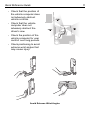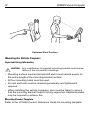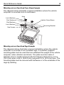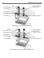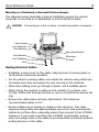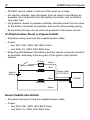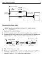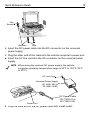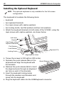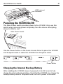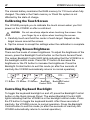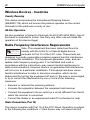
1
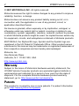
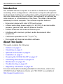
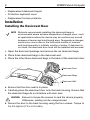
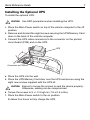
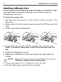
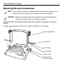
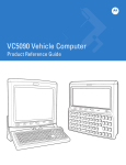
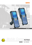
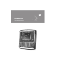
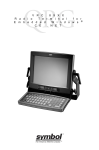
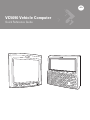
VC5090 Vehicle Computer
Quick Reference Guide
2
VC5090 Vehicle Computer
© 2007 MOTOROLA, INC. All rights reserved.
Motorola reserves the right to make changes to any product to improve
reliability, function, or design.
Motorola does not assume any product liability arising out of, or in
connection with, the application or use of any product, circuit, or
application described herein.
No license is granted, either expressly or by implication, estoppel, or
otherwise under any patent right or patent, covering or relating to any
combination, system, apparatus, machine, material, method, or process
in which Motorola products might be used. An implied license exists only
for equipment, circuits, and subsystems contained in Motorola products.
MOTOROLA, the Stylized M Logo, Symbol and the Symbol logo are
registered in the US Patent & Trademark Office. Other product names
mentioned in this manual may be trademarks or registered trademarks of
their respective companies and are hereby acknowledged.
Motorola, Inc.
One Motorola Plaza
Holtsville, N.Y. 11742-1300, USA
http://www.symbol.com
Warranty
Subject to the terms of Motorola’s hardware warranty statement, the
VC5090 Vehicle Computer products are warranted against defects in
workmanship and materials for a period of one year from the date of
shipment. For the complete Motorola hardware product warranty
statement, go to: http://www.symbol.com/warranty.
Patents
This product is covered by one or more patents. For patent information
go to: http://www.symbol.com/patents.
Quick Reference Guide
3
Introduction
The VC5090 Vehicle Computer is a vehicle or fixed-mount computer
consisting of two configurations: a full-screen computer with optional
keyboard and a half screen configuration with a integrated keyboard. You
can enter data using the touch screen, the keyboard, an optional bar
code scanner, or a combination of the three. The data is transmitted
wirelessly to a host computer. The vehicle computer features:
• Ergonomic design with color LCD touch screen
• Internal wide-range power supply (9 - 60 VDC) to accommodate
propane, gasoline, and electric-powered forklifts
• Internal antennas with external antenna port
• Interfaces with scanners, printers, audio devices and other
peripherals
• Continuous operation at -30 °C (-22 °F)
• Pre-loaded with terminal emulation software.
About This Guide
This guide contains the following:
•
•
•
•
•
•
•
•
•
Features on page 4
Unpacking on page 5
Optional Accessories on page 5
Installation on page 6
Powering the VC5090 On/Off on page 21
Connecting Accessories on page 24
Maintenance on page 24
Troubleshooting on page 25
Regulatory Information on page 26.
For more information including installation instructions, refer to the
VC5090 Product Reference Guide, p/n 72E-76347-xx available at
http://support.symbol.com.
4
VC5090 Vehicle Computer
Features
Mounting Bracket
Quick Access
Panel
Optional Keyboard
Antenna Port for Optional
External Antenna
Main Power Switch
Display
WLAN COMM LED
Power LED
Power Button
Backlight
Control Button
Backlight
Control LED
Built-In Keyboard
Quick Reference Guide
5
UPS/Memory Card Door
Desiccant Door
USB Ports
(Client
and Host)
Power
Connector
COM2 Port
Connector
Audio
COM1 Port
Connector Connector
USB/
Keyboard
Connector
Unpacking
The following items are contained in the box:
• VC5090 vehicle computer
•
•
•
•
•
mounting bracket
hardware kit
desiccant door kit
power cable
this guide.
NOTE The hardware kit contains items that might not be used during
installation. Keep the hardware kit in a safe place for future use.
Optional Accessories
•
•
•
•
•
•
•
•
•
Heated keyboard with bracket assembly
Scanners and cables
Headset/Handset
Vehicle Motion Detector Kit
Printer cables
Adjustable handles
RS-232 and USB ActiveSync cables
AC power supply
Uninterruptable power supply (UPS)
6
VC5090 Vehicle Computer
• Replacement desiccant bag kit
• Protective keyboard cover
• Replacement screen protector.
Installation
Installing the Desiccant Door
NOTE Motorola recommends installing the desiccant bags in
environments where extreme temperature changes occur, such
as applications where the device may be continuously moved
between a freezer and a hot/humid area. Temperature changes
would occur more often in the hot/humid months of summer
and less frequently in cold/dry months of winter. If desiccant is
not used, the desiccant door must still be installed and secured.
1.
Open the desiccant package and remove the six desiccant bags.
2.
Place three desiccant bags in the desiccant well.
3.
Place the other three desiccant bags in the back of the desiccant door.
Desiccant Door
Desiccant Bags
Desiccant Well
4.
Ensure that the door seal is in place.
5.
Carefully place the desiccant door onto the back housing. Ensure that
the desiccant bags do not interfere with door seal.
CAUTION
6.
Ensure to torque the screws to seal the device properly.
Otherwise, sealing can be compromised.
Secure the door to the back housing using the four screws. Torque to
9 ± 0.5 kgf.cm (7.8 ± 0.4 in-lbs).
Quick Reference Guide
7
Installing the Optional UPS
To install the optional UPS:
CAUTION
Use ESD precautions when installing the UPS.
1.
Place the Main Power switch on top of the vehicle computer to the off
position.
2.
Remove and discard the eight screws securing the UPS/Memory Card
door on the back of the vehicle computer.
3.
Connect the UPS cable connectors to the connector on the printed
circuit board (PCB) and on the UPS.
UPS
Connector on PCB
4.
Place the UPS into the well.
5.
Place the UPS/Memory Card door over the UPS and secure using the
eight new screws supplied with the UPS kit.
CAUTION
Ensure to torque the screws to seal the device properly.
Otherwise, sealing can be compromised.
6.
Torque the screws to 9 +/- 0.5 kgf.cm (7.8 ± 0.4 in-lbs).
7.
Place the Main Power switch to the on position.
Its takes four hours to fully charge the UPS.
8
VC5090 Vehicle Computer
Installing a Memory Card
A memory card (Secure Digital) provides secondary non-volatile storage.
The card holder is located on the back of the VC5090 under the
UPS/Memory Card door.
To install the memory card:
1.
Place the Main Power switch on the top of the vehicle computer to the
off position.
2.
Remove and discard the eight screws securing the UPS/Memory Card
door.
3.
Lift the card holder retaining door.
4.
Position the memory card, with the contacts down, into the card
holder. The memory card corner notch fits into the holder only one
way.
5.
Snap the retaining door closed.
6.
Replace the UPS/Memory Card door and secure using eight new
screws.
CAUTION
Ensure to torque the screws to seal the device properly.
Otherwise, sealing can be compromised.
7.
Torque the screws to 9 +/- 0.5 kgf.cm (7.8 ± 0.4 in-lbs).
8.
Place the Main Power switch to the on position.
Quick Reference Guide
9
Mounting Bracket Installation
NOTE The vehicle computer and bracket must be firmly secured to a
surface that can support the vehicle computer’s weight.
CAUTION
Motorola requires that the supplied mounting bracket be
used when mounting the vehicle computer.
Assemble the mounting bracket onto the vehicle computer as shown
below.
Torque cap screws to 276 ± 8.7 kgf.cm (239.6 ± 7.6 in-lbs).
Mounting Bracket
Cap Screw
Flat Washer
Lock Washer
Friction Pad
Friction Pad
Mounting Area
10
VC5090 Vehicle Computer
Installing the VC5090 in a Forklift
CAUTION
A qualified engineer must perform the installation in a
vehicle. Improper installation can injure the operator or
damage the vehicle and/or VC5090.
Follow the instructions below to properly install the VC5090 in a forklift.
• Determine the best location for mounting the vehicle computer taking
into consideration the driver’s field of view and ease of accessing the
vehicle computer.
• Install the appropriate mounting hardware. The VC5090 ships with
four cap screws (3/8” - 16 - 2”) for securing the mounting bracket. If
the supplied cap screws are not long enough, use 3/8” - 16 - X
stainless steel cap screws where X represents the length in inches of
the required cap screws.
• Connect the vehicle computer to the vehicle’s wiring system.
Positioning the Vehicle Computer
• Position the vehicle computer to ensure proper ventilation around the
device.
• Determine the best position for the vehicle computer and all the
associated components. If a similar vehicle computer was previously
installed, check to see if the position it used is suitable for the
VC5090.
• Test the installation for at least 30 minutes before installing on another
vehicle:
Quick Reference Guide
-
Check that the position of
the vehicle computer does
not adversely obstruct
vehicle controls.
-
Check that the vehicle
computer does not
adversely obstruct the
driver's view.
-
Check the position of the
vehicle computer for user
comfort over long periods.
-
Check positioning to avoid
extreme wrist angles that
may cause injury.
Avoid Extreme Wrist Angles
11
12
VC5090 Vehicle Computer
Optimum Wrist Position
Mounting the Vehicle Computer
Important Fixing Information
CAUTION
Any modification to supplied mounting bracket could cause
failure of the unit and/or mountings.
• Mounting surface must be flat and stiff and it must extend evenly for
the entire length of the mounting bracket surface.
• All four mounting holes must be used.
• All nuts and bolts must be checked periodically and tightened if
required.
• When installing the vehicle computer, care must be taken to ensure
that the mounting bracket footprint is fully supported. Additional plates
may be required to achieve this.
Mounting Bracket Template
Refer to the VC5090 Product Reference Guide for mounting template.
Quick Reference Guide
13
Mounting onto an Over-Head Cross-Beam Example
The diagram below illustrates a typical installation where the vehicle
computer is mounted onto a cross-beam.
Lock Washers
Flat Washers
Nuts
Vehicle Cross-Beam
Flat Washers
Lock Washers
Cap Screws
Mounting Bracket
Mounting onto an Over-Head Cage Example
The diagrams below illustrates a typical installation where the vehicle
computer is mounted on an overhead cage. A customer supplied
mounting plate must be used that can withstand the weight of the vehicle
computer under vibration and shock. The plate must be made of
stainless steel or hardened steel with the following dimensions: 3.0 in.
(76.0 mm) wide, 8.66 in. (220.0 mm) long and 0.2 in. (5.0 mm) thick. The
mounting plate must be secured with hardware or to the underside of the
cage by welding.
14
VC5090 Vehicle Computer
Nuts
Lock Washers
Customer Supplied
Mounting Plate
Flat Washers
Flat Washers
Lock Washers
Mounting Bracket
Cap Screws
Mounting on Flat Overhead Beams
Nuts
Lock Washers
Flat Washers
Customer Supplied
Mounting Plate
Welded to Beams
Flat Washers
Lock Washers
Cap Screws
Mounting Bracket
Mounting on Transverse Overhead Beams
Quick Reference Guide
15
Mounting on a Dashboard or Horizontal Surface Example
The diagram below illustrates a typical installation where the vehicle
computer is mounted on a dashboard or horizontal flat surface.
CAUTION
If mounting to a thin surface, a reinforcing plate is required.
Cap Screws
Lock Washers
Flat Washers
Mounting Bracket
Flat Washers
Lock Washers
Mounting
Surface
Nuts
Routing Electrical Cables
• Establish a neat route for the cable, staying clear of moving parts or
hot surfaces whenever possible.
• Fix the cable to existing cable runs inside the vehicle using cable ties,
but make sure they are away from any moving or hot surfaces.
• When the cabling must go through a panel, use a suitable gland.
• When fixing the conduit or cable on the outside of a vehicle, use
P-Clips. Either drill and tap the hole or use a nut and bolt to secure the
clip.
• Ensure the cable does not have tight bends. The minimum
recommended radius is 2.5".
• Ensure cables do not swing or chafe on the structure. This often
requires using cable ties approximately every foot, and ensuring the
cables do not flex often, especially where they connect to the VC5090.
However, if you must re-position the VC5090 occasionally, ensure
there is enough slack in the cable to accommodate movement without
putting tension on the cable.
16
VC5090 Vehicle Computer
• DO NOT wind a cable in and out of the mesh on a cage.
• On electric vehicles, take the power from as close to the battery as
possible, but not directly from the battery terminals, and not before
any main fuse.
• On gasoline, diesel or propane vehicles, take the power from as close
to the battery terminals as possible, and avoid using existing wiring.
• Ensure that all fuses are as close as possible to the power source.
12-24 Volt Gasoline, Diesel, or Propane Forklifts
• All power wiring must use the supplied power cable.
• Fuses:
-
two 3AG, 20A, 250V, SLO BLO fuses
-
one 3AG, 1A, 250V, SLO BLO fuse.
• Keep the path between the battery and the vehicle computer as short
as possible, and away from any part of the ignition high tension
system.
1A Fuse
Yellow
Ignition Switch
Red
Vehicle
Battery
Power Cable
25-71919-01
20A Fuse
Black
20A Fuse
Green
Electric Forklifts 24 to 60 Volts
• All power wiring must use the supplied power cable.
• Fuses:
-
two 3AG, 20A, 250V, SLO BLO fuses
-
one 3AG, 1A, 250V, SLO BLO fuse.
VC5090
Quick Reference Guide
17
or
1 A Fuse
Yellow
Switch
Red
20A Fuse
Vehicle
Battery
Power Cable
25-71919-01
Black
VC5090
20A Fuse
Green
Connecting the Power Cable
NOTE See the vehicle Owner's Manual for specific wiring
information.
1.
Disconnect the vehicle battery.
2.
Connect the green wire to the vehicle’s negative power source.
3.
Place a fuse and fuse holder in-line of the red, black and yellow wires
approximately four inches from the cable end, as shown below.
Wire
Shrink Tubing Wire
Shrink Tubing
Fuse Holder
Fuse
Fuse Holder
4.
Slide shrink tubing over wires.
5.
Strip the wires (0.4 in./10 mm) and insert into the fuse holder. Crimp
fuse holder ends to ensure a proper electrical connection (use
Thomas & Betts WT-11-M crimp tool or equivalent).
18
VC5090 Vehicle Computer
6.
Heat shrink tubing.
7.
Connect the red wire to the vehicle's positive power source. Connect
the black wire to the vehicle's negative power source.
NOTE The vehicle computer contains a Ignition Sense feature that
detects when the ignition switch is turned off. This allows the
device to draw power for a preset amount of time to allow
proper shutdown of applications then removes power so that it
would not drain the vehicle’s battery.
8.
Connect the yellow wire to the vehicle's ignition switch. If you do not
plan on using the Ignition Sense feature, connect the yellow wire to
the vehicle’s positive power source.
9.
Ensure the wiring connections created are sufficiently insulated from
each other.
10. Re-connect
the vehicle battery.
11. Insert
the power cable connector into the vehicle computer's Power
port. Align the keyway on the power connector with the notch on the
vehicle computer’s power port.
Installing the VC5090 on a Desktop
To mount the vehicle computer on a desktop:
CAUTION
1.
If mounting to a thin surface such as drywall or plywood, a
reinforcing plate is required.
Install the mounting bracket to the desktop using four cap screws,
eight washers and four nuts.
NOTE The VC5090 ships with four cap screws (3/8” - 16 - 2”) for
securing the mounting bracket. If the supplied cap screws
are not long enough, use 3/8” - 16 - X stainless steel cap
screws where X represents the length in inches of the
required cap screws.
Quick Reference Guide
19
Cap
Screws
Washers
Nuts
2.
Insert the DC power cable into the DC connector on the universal
power supply.
3.
Plug the other end of the cable into the vehicle computer’s power port.
4.
Insert the AC line cord into the AC connector on the universal power
supply.
NOTE When using the optional AC power supply, the vehicle
computer operating temperature range is 50°F to 104°F (10°C
to 40°C).
AC Line Cord
Universal Power Supply
(50-14001-004 or
50-14001-004R)
Power Port
5.
DC Power Cable
(25-71920-01 or
25-71920-01R)
Plug the other end of the AC power cable into a wall outlet.
20
VC5090 Vehicle Computer
Installing the Optional Keyboard
NOTE The optional keyboard is only available for the full-screen
configuration.
The keyboard kit contains the following items:
• keyboard
• two keyboard brackets
• four caps screws with captive washers
• two locking knobs, two flat washers and two lock washers.
1.
Attach the keyboard brackets to both sides of the VC5090, using the
caps screws with captive washers, as shown below:
Left Hand
Bracket
Cap Screws with
Captive Washers
Flat Washer
Lock Washer
Alignment Pin
Locking Knob
Alignment Pin Holes
2.
Torque the screws to 230 kgf/cm (200 in-lbs).
3.
Squeeze the quick release tabs on the
keyboard and align the keyboard with
the brackets.
4.
Release the quick release tabs to insert
the alignment pins through an alignment
pin hole on each of the brackets.
5.
Insert the keyboard locking knobs
through the washers and brackets and
screw into the keyboard.
6.
Plug the keyboard cable into the USB/Keyboard connector.
Quick Release Tabs
Quick Reference Guide
21
USB/Keyboard
Connector
Powering the VC5090 On/Off
The Main Power switch provides power to the VC5090. Only use this
switch when removing power completely from the device. Everything
stored in RAM is lost.
Main Power Switch
Use the Power button on the Quick Access Panel to place the VC5090
into Suspend mode or wake the VC5090 from Suspend mode.
Power Button
Charging the Internal Backup Battery
After installing the VC5090, leave it powered on for 24 hours to fully
charge the internal backup battery. Note that the VC5090 can charge the
backup battery while in Suspend mode, but not if power is removed.
22
VC5090 Vehicle Computer
The internal battery maintains the RAM memory for 72 hours when fully
charged. The data in the Flash memory or Flash file system is not
affected by the state of charge.
Calibrating the Touch Screen
The VC5090 prompts you to calibrate the touch screen when you first
power on the VC5090 or after a cold-boot.
CAUTION
Do not use sharp objects when touching the screen. Use
your finger tip or a stylus when touching the screen.
1.
Carefully touch and hold the center of each target. Repeat as the
target moves around the screen.
2.
Tap the screen to accept the settings when the calibration is complete.
Controlling Screen Brightness
There are five levels of screen brightness. To adjust the brightness of the
screen, press the Backlight Control button on the Quick Access Panel.
The amber Backlight Control LED lights indicating that the VC5090 is in
the backlight control mode. Press the P1 button to decrease the
brightness or the P2 button to increase the brightness. Press the
Backlight Control button to exit this mode (or after five seconds of
inactivity the VC5090 automatically returns to normal operation).
P1 Button P2 Button P3 Button
Backlight Backlight Control
Control LED
Button
Controlling Keyboard Backlight
To toggle the keyboard backlight on and off, press the Backlight Control
button on the Quick Access Panel. The amber Backlight Control LED
lights indicating that the VC5090 is in the backlight control mode. Press
the P3 button to toggle the keyboard backlit. After three seconds of
inactivity, the VC5090 returns to normal operation. Press the Backlight
Control button to exit this mode (or after five seconds of inactivity the
VC5090 automatically returns to normal operation).
Quick Reference Guide
23
Resetting the Vehicle Computer
If the vehicle computer stops responding to inputs, perform a warm boot
or cold boot.
Performing a Warm Boot
A warm boot restarts the vehicle computer and saves all stored records
and entries.
NOTE Files that remain open during a warm boot may not be retained.
To perform a warm boot, press the Power button and the P2 button
simultaneously and release.
Performing a Cold Boot
A cold boot restarts the vehicle computer, but erases all stored records
and entries in RAM. Data saved in flash memory or a memory card is not
lost. In addition it returns formats, preferences and other settings to the
factory default settings. There are two ways to perform a cold boot:
• Simultaneously press and hold the Power, P1 and P3 buttons.
• Turn off the Main Power switch on the top of the vehicle computer,
press the Power, P1 and P3 buttons simultaneously then turn the
Main Power switch to the on position.
Programmable Keys
The programmable keys on the Quick Access Panel (P1, P2, P3) can be
set to perform certain functions, such as switching between applications
or emulator sessions.
To set a programmable key:
1.
From the Start menu, select Settings > Control Panel.
2.
Select the Programmable Keys icon.
3.
In the Key: drop-down list, select the key to program.
4.
In the Action drop-down list, select the function to assign to the key to
perform.
5.
Tap OK.
24
VC5090 Vehicle Computer
Connecting Accessories
Connect an optional scanner, ActiveSync serial or USB cable, audio or
USB device using the appropriate connector on the bottom of the
VC5090. Cables are available from Motorola.
You may also use the USB port for ActiveSync connection, if the serial
ports are used for another purpose. This cable is also available from
Motorola. Refer to the VC5090 Product Reference Guide for information
of additional accessories.
Maintenance
The vehicle computer is factory-sealed (except for the desiccant door
and UPS/Memory Card door) and contains no user-serviceable parts.
Only qualified Service Centers should service the vehicle computer.
Use the protective caps that came with the vehicle computer to protect
unused connectors.
• Clean the casing, keyboard, and display window by wiping with a soft
cloth. Use a damp cloth if necessary.
• Never use solvents or abrasive cleaners. You may damage the
display or keyboard.
Desiccant Bag Replacement
Optional desiccant bags can be used in environments where extreme
temperature changes occur. See Installing the Desiccant Door on page 6
for installing the desiccant bags. Discard the original screws and replace
the door using the screws that come with the new desiccant kit.
Quick Reference Guide
25
Troubleshooting
Problem
VC5090
does not
power on or
shuts off
suddenly.
Cannot see
characters
on display.
Application
does not
respond.
Cause
Solution
Main Power switch on top of
vehicle computer is in the off
position.
Turn the Main Power switch to the
on position.
Power cable not connected or
unplugged.
Connect power cable to power
cable port on bottom of the
vehicle computer. Press the
Power button to wake up the
VC5090.
If VC5090 is powered by a
vehicle battery, the vehicle
battery is depleted.
Replace or charge the vehicle
battery.
The power cable ignition
sense wire (yellow) is not
connected properly.
Verify that the power cable is
connected properly. See Routing
Electrical Cables on page 15.
VC5090 not powered on.
Check that the Main Power switch
on the top of the VC5090 is in the
on position.
Press the Power button.
Screen is too bright or too
dark.
Adjust the brightness; see
Controlling Screen Brightness on
page 22.
VC5090 is in Suspend mode
(green Power LED is off)
Press the Power button to wake
up the VC5090.
VC5090 is not
communicating with the AP
(Communication LED is off).
Bring the VC5090 closer to the
AP. If problem continues, contact
your System Administrator.
26
VC5090 Vehicle Computer
Problem
Optional
scanner
does not
operate.
Cause
Solution
Scanner is not properly
connected to the VC5090.
Connect the scanner to the COM1
port and power up the vehicle
computer. If the problem
continues, refer to the scanner
Product Reference Guide or see
your System Administrator.
SerialWedge application is
not enabled or set to the
correct COM Port.
Ensure that the SerialWedge
application is enabled and set to
the correct port. See VC5090
Product Reference Guide for
more information.
Regulatory Information
All Symbol devices are designed to be compliant with rules and
regulations in locations they are sold and will be labeled as required.
This device is approved under the Symbol Technologies brand; Symbol
Technologies, Inc., is the Enterprise Mobility business of Motorola, Inc
(“Motorola”).
Regulatory Information is available in French, Italian, German, Spanish
(Spain), Portuguese, Japanese, Korean, Russian, Simplified Chinese
and Traditional Chinese. Please see following web site:
http://support.symbol.com and look for your specific product.
Any changes or modifications to Symbol equipment, not expressly
approved by Symbol Technologies, could void the user's authority to
operate the equipment.
Antennas: Use only the supplied or an approved replacement antenna.
Unauthorized antennas, modifications, or attachments could cause
damage and may violate regulations.
CAUTION
Only use Symbol approved and UL Listed accessories,
battery packs and battery chargers.
Do NOT attempt to charge damp/wet mobile computers or
batteries. All components must be dry before connecting to
an external power source.
Quick Reference Guide
27
Products Equipped with Bluetooth® Wireless
Technology
This product contains Bluetooth Complimentary Subsystems:
• BT ID:B01825
• BT ID:B02413
Country Approvals
Regulatory markings are applied to the device signifying the radio(s) are
approved for use in the following countries: United States, Canada,
Australia, Japan, China and Europe 1, 2.
Please refer to the Symbol Declaration of Conformity (DoC) for details of
other country markings. This is available at
http://www2.symbol.com/doc/.
Note 1: For 2.4GHz Products: Europe includes, Austria, Belgium, Czech
Republic, Cyprus, Denmark, Estonia, Finland, France, Germany,
Greece, Hungary, Iceland, Ireland, Italy, Latvia, Liechtenstein, Lithuania,
Luxembourg, Malta, Netherlands, Norway, Poland, Portugal, Slovak
Republic, Slovenia, Spain, Sweden, Switzerland and the United
Kingdom.
Note 2: The use of 5GHz RLAN's has varying restrictions of use; please
refer to the Symbol Declaration of Conformity (DoC) for details.
CAUTION
Operation of the device without regulatory approval is
illegal.
Health and Safety Recommendations
Ergonomic Recommendations
CAUTION
In order to avoid or minimize the potential risk of ergonomic
injury follow the recommendations below. Consult with your
local Health & Safety Manager to ensure that you are
adhering to your company's safety programs to prevent
employee injury.
• Reduce or eliminate repetitive motion
28
•
•
•
•
•
•
•
•
•
•
VC5090 Vehicle Computer
Maintain a natural position
Reduce or eliminate excessive force
Keep objects that are used frequently within easy reach
Perform tasks at correct heights
Reduce or eliminate vibration
Reduce or eliminate direct pressure
Provide adjustable workstations
Provide adequate clearance
Provide a suitable working environment
Improve work procedures.
Warnings for Use of Wireless Devices
Please observe all warning notices with regard to the usage of wireless
devices.
Potentially Hazardous Atmospheres
You are reminded of the need to observe restrictions on the use of radio
devices in fuel depots, chemical plants etc. and areas where the air
contains chemicals or particles (such as grain, dust, or metal powders)
and any other area where you would normally be advised to turn off your
vehicle engine.
Hearing Aids
The wireless device may interfere with some hearing aids. In the event of
interference you may want to consult your hearing aid supplier to discuss
solutions.
Other Medical Devices
Please consult your physician or the manufacturer of the medical device,
to determine if the operation of your wireless product may interfere with
the medical device.
Quick Reference Guide
29
FCC / EU RF Exposure Guidelines
Safety Information
The device complies with Internationally recognized standards covering
Specific Absorption Rate (SAR) related to human exposure to
electromagnetic fields from radio devices.
Reducing RF Exposure - Use Properly
It is advisable to use the device only in the normal operating position.
Remote and Standalone Antenna Configurations
To comply with FCC RF exposure requirements, antennas that are
mounted externally at remote locations or operating near users at
stand-alone desktop of similar configurations must operate with a
minimum separation distance of 20 cm from all persons.
To satisfy FCC RF exposure requirements, a mobile transmitting device
must operate with a minimum separation distance of 20 cm or more from
a person's body.
Power Supply
Use only a Symbol approved power supply 50-14001-004/-004R output
rated 12 VDC and minimum 9 A. The power supply is certified to
EN60950-1 with SELV outputs. Use of alternative power supply will
invalidate any approval given to this device and may be dangerous.
Batteries
Please follow the local regulations when disposing of re-chargeable
batteries.
Taiwan - Recycling
EPA (Environmental Protection Administration)
requires dry battery producing or importing firms in
accordance with Article 15 of the Waste Disposal
Act are required to indicate the recycling marks on
the batteries used in sales, giveaway or promotion.
Contact a qualified Taiwanese recycler for proper battery disposal.
30
VC5090 Vehicle Computer
Wireless Devices - Countries
Country Roaming
This device incorporates the International Roaming feature
(IEEE802.11d) which will ensure the product operates on the correct
channels for the particular country of use.
Ad-Hoc Operation
Ad-Hoc operation is limited to Channels 36-48 (5150-5250 MHz). Use of
this band is restricted to Indoor Use Only, any other use will make the
operation of this device illegal.
Radio Frequency Interference Requirements
Note: This equipment has been tested and found to
comply with the limits for a Class B digital device,
pursuant to Part 15 of the FCC rules. These limits are
designed to provide reasonable protection against harmful interference
in a residential installation. This equipment generates, uses, and can
radiate radio frequency energy and, if not installed and used in
accordance with the instructions, may cause harmful interference to
radio communications. However there is no guarantee that interference
will not occur in a particular installation. If this equipment does cause
harmful interference to radio or television reception, which can be
determined by turning the equipment off and on, the user is encouraged
to try to correct the interference by one or more of the following
measures:
Tested to comply
with FCC Standards
FOR HOME OR OFFICE USE
• Reorient or relocate the receiving antenna
• Increase the separation between the equipment and receiver
• Connect the equipment into an outlet on a circuit different from that to
which the receiver is connected
• Consult the dealer or an experienced radio/TV technician for help.
Radio Transmitters (Part 15)
This device complies with Part 15 of the FCC Rules. Operation is subject
to the following two conditions: (1) this device may not cause harmful
Quick Reference Guide
31
interference, and (2) this device must accept any interference received,
including interference that may cause undesired operation.
Radio Frequency Interference Requirements - Canada
This Class B digital apparatus complies with Canadian ICES-003. Cet
appareil numérique de la classe B est conforme à la norme NMB-003 du
Canada.
Radio Transmitters
This device complies with RSS 210 of Industry & Science Canada.
Operation is subject to the following two conditions: (1) this device may
not cause harmful interference and (2) this device must accept any
interference received, including interference that may cause undesired
operation.
Label Marking: The Term “IC:” before the radio certification only signifies
that Industry Canada technical specifications were met.
Marking and European Economic Area (EEA)
The use of 2.4 GHz RLAN's, have the following restrictions:
• Maximum radiated transmit power of 100 mW EIRP in the frequency
range 2.400 -2.4835 GHz
• France, equipment is restricted to 2.4 - 2.454 GHz
• Italy requires a user license for outside usage.
The use of 5GHz RLAN's has varying restrictions for use within the EEA;
please refer to the Symbol Declaration of Conformity (DoC) for details at
http://www2.symbol.com/doc/
Bluetooth® Wireless Technology for use through the EEA has the
following restrictions:
• Maximum radiated transmit power of 100mW EIRP in the frequency
range 2.400 -2.4835 GHz
• France, outside usage is restricted to 10mW EIRP
• Italy requires a user license for outside usage.
32
VC5090 Vehicle Computer
Statement of Compliance
Symbol Technologies, Inc., hereby, declares that this device is in
compliance with the essential requirements and other relevant provisions
of Directives 1999/5/EC. Declaration of Conformities may be obtained
from http://www2.symbol.com/doc/
Other Countries
2.4GHz Radio Devices:
Mexico
-
Sri Lanka -
Restrict Frequency Range to: 2.450 - 2.4835 GHz.
Restrict Frequency Range to: 2.400 - 2.430 GHz.
Battery Information
Symbol rechargeable battery packs are designed and constructed to the
highest standards within the industry. However, there are limitations to
how long a battery can operate or be stored before needing
replacement. Many factors affect the life of a battery pack such as heat,
cold, customer usage profiles, age, and severe drops.
When batteries are stored over a year, battery cell manufacturers advise
that some irreversible deterioration in overall battery quality may occur.
To minimize this loss, they recommend storing batteries half charged in a
dry, cool place between 41° and 77°F (5° and 25°C), the cooler the
better) and removed from the equipment to prevent the loss of capacity.
Batteries should be charged to half capacity at least once a year. If an
electrolyte leakage is observed, avoid any contact with the affected area
and properly dispose of the battery.
Replace the battery when a significant loss of run time is detected.
Batteries must be charged within the 32° to 104°F (0° to 40°C)
temperature range.
The standard warranty period for all Symbol batteries is 30 days,
regardless if the battery was purchased separately or included as part of
the mobile computer. For more information on Symbol batteries, please
visit http://mysymbolcare.symbol.com/battery/batbasics1.html.
Quick Reference Guide
33
Waste Electrical and Electronic Equipment
(WEEE)
English: For EU Customers: All products at the end of their life must be returned
to Motorola for recycling. For information on how to return product, please go to:
http://www.symbol.com/environmental_compliance.
Bulgarish: За клиенти от ЕС: След края на полезния им живот всички
продукти трябва да се връщат на Motorola за рециклиране. За информация
относно връщането на продукти, моля отидете на адрес:
http://www.symbol.com/weeelink.
Dansk: Til kunder i EU: Alle produkter skal returneres til Motorola til recirkulering,
når de er udtjent. Læs oplysningerne om returnering af produkter på:
http://www.symbol.com/environmental_compliance.
Deutsch: Für Kunden innerhalb der EU: Alle Produkte müssen am Ende ihrer
Lebensdauer zum Recycling an Motorola zurückgesandt werden. Informationen
zur Rücksendung von Produkten finden Sie unter
http://www.symbol.com/environmental_compliance.
Eesti: EL klientidele: kõik tooted tuleb nende eluea lõppedes tagastada
taaskasutamise eesmärgil Symbol'ile. Lisainformatsiooni saamiseks toote
tagastamise kohta külastage palun aadressi:
http://www.symbol.com/environmental_compliance.
Español: Para clientes en la Unión Europea: todos los productos deberán
entregarse a Motorola al final de su ciclo de vida para que sean reciclados. Si
desea más información sobre cómo devolver un producto, visite:
http://www.symbol.com/environmental_compliance.
Français : Clients de l'Union Européenne : Tous les produits en fin de cycle de vie
doivent être retournés à Motorola pour recyclage. Pour de plus amples
informations sur le retour de produits, consultez :
http://www.symbol.com/environmental_compliance.
34
VC5090 Vehicle Computer
Italiano: per i clienti dell'UE: tutti i prodotti che sono giunti al termine del rispettivo
ciclo di vita devono essere restituiti a Motorola al fine di consentirne il riciclaggio.
Per informazioni sulle modalità di restituzione, visitare il seguente sito Web:
http://www.symbol.com/environmental_compliance.
Magyar: Az EU-ban vásárlóknak: Minden tönkrement terméket a Motorola
vállalathoz kell eljuttatni újrahasznosítás céljából. A termék visszajuttatásának
módjával kapcsolatos tudnivalókért látogasson el a
http://www.symbol.com/environmental_compliance weboldalra.
Nederlands: Voor klanten in de EU: alle producten dienen aan het einde van hun
levensduur naar Motorola te worden teruggezonden voor recycling. Raadpleeg
http://www.symbol.com/environmental_compliance voor meer informatie over het
terugzenden van producten.
Português: Para clientes da UE: todos os produtos no fim de vida devem ser
devolvidos à Motorola para reciclagem. Para obter informações sobre como
devolver o produto, visite: http://www.symbol.com/environmental_compliance.
Românesc: Pentru clienţii din UE: Toate produsele, la sfârşitul duratei lor de
funcţionare, trebuie returnate la Motorola pentru reciclare. Pentru informaţii
despre returnarea produsului, accesaţi: http://www.symbol.com/weeelink.
Slovenski: Za kupce v EU: vsi izdelki se morajo po poteku življenjske dobe vrniti
podjetju Motorola za reciklažo. Za informacije o vraèilu izdelka obišèite:
http://www.symbol.com/environmental_compliance.
Quick Reference Guide
35
Suomi: Asiakkaat Euroopan unionin alueella: Kaikki tuotteet on palautettava
kierrätettäväksi Motorola-yhtiöön, kun tuotetta ei enää käytetä. Lisätietoja tuotteen
palauttamisesta on osoitteessa
http://www.symbol.com/environmental_compliance.
Svenska: För kunder inom EU: Alla produkter som uppnått sin livslängd måste
returneras till Motorola för återvinning. Information om hur du returnerar produkten
finns på http://www.symbol.com/environmental_compliance.
Service Information
If you have a problem using the equipment, contact your facility’s Technical or
Systems Support. If there is a problem with the equipment, they will contact the
Motorola Enterprise Mobility Support at: http:www.symbol.com/customersupport.
For the latest version of this guide go to: http://www.symbol.com/manuals.
Motorola, Inc.
One Motorola Plaza
Holtsville, New York 11742, USA
1-800-927-9626
http://www.symbol.com
MOTOROLA and the Stylized M Logo and Symbol and the Symbol logo are registered in the U.S.
Patent and Trademark Office. All other product or service names are the property of their
registered owners. © Motorola, Inc. 2007
72-76346-03 Revision A - June 2007