1
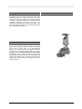
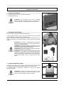
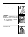
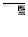
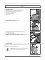
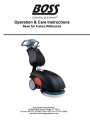
sosr CLEAN/NC EQUIPMENT Operation & Care Instructions Save for Future Reference Boss Cleaning Equipment 10708 N 46th Street, Tampa, FL 33617 Phone: 800-232-2635/813-549-1435 Fax: 813-971-6090 www.bosscleaningequipment.com TABLE OF CONTENTS RECEIVING THE MACHINE .......................................................................................................................................................... 4 FOREWORD .................................................................................................................................................................................. 4 TECHNICAL DESCRIPTION.......................................................................................................................................................... 5 SYMBOLS USED ON THE MACHINE ........................................................................................................................................... 6 GENERAL SAFETY REGULATIONS ............................................................................................................................................ 7 PREPARING THE MACHINE......................................................................................................................................................... 8 1. HANDLING THE PACKAGED MACHINE............................................................................................................................... 8 2. HOW TO UNPACK THE MACHINE........................................................................................................................................ 8 3. BATTERY INSTALLATION/CONNECTION............................................................................................................................ 8 4. CONNECTOR CONNECTON................................................................................................................................................. 9 5. RECHARGING THE BATTERIES .......................................................................................................................................... 9 6. BATTERY CHARGE LEVEL GAUGE ..................................................................................................................................... 9 7. FASTENING THE HANDLEBAR .......................................................................................................................................... 10 8. DETERGENT SOLUTION .................................................................................................................................................... 10 9. RECOVERY TANK ............................................................................................................................................................... 10 10. SOLUTION TANK ............................................................................................................................................................... 11 OPERATION ................................................................................................................................................................................ 12 1.PREPARING TO WORK........................................................................................................................................................ 12 2.OVERFLOW DEVICE ............................................................................................................................................................ 12 3.FORWARD MOVEMENT....................................................................................................................................................... 13 AFTER WORK IS TERMINATED................................................................................................................................................. 14 DAILY MAINTENANCE................................................................................................................................................................ 15 1.CLEANING THE RECOVERY TANK..................................................................................................................................... 15 2.CLEANING THE SQUEEGEE ............................................................................................................................................... 15 3.REPLACING THE SQUEEGEE RUBBERS........................................................................................................................... 16 4.BRUSHES DISASSEMBLY ................................................................................................................................................... 16 SCHEDULED MAINTENANCE .................................................................................................................................................... 17 1.CLEANING THE SQUEEGEE TUBE..................................................................................................................................... 17 2.CLEANING THE FILTER AND THE SOLUTION TANK ........................................................................................................ 17 CHECKING OPERATION ............................................................................................................................................................ 18 1.ELECTRIC SYSTEM SAFETY .............................................................................................................................................. 18 2.INSUFFICIENT WATER ON THE BRUSHES ....................................................................................................................... 18 3.THE MACHINE DOES NOT CLEAN WELL........................................................................................................................... 18 4.THE SQUEEGEE DOES NOT DRY THE FLOOR PERFECTLY........................................................................................... 18 5.TOO MUCH FOAM IS GENERATED .................................................................................................................................... 18 BRUSH SELECTION AND USE................................................................................................................................................... 19 3 Receiving the machine Immediately check, when receiving the machine, that all the materials indicated on delivery documents have been received and also that the machine has not been damaged in transit. If it has been damaged, this damage must be immediately reported to the shipper and also to our customer’s service department. Only acting promptly in this manner will make it possible to receive missing material and to be compensated for damage. Foreword This is a floor scrubbing machine that is able to clean any type of floor by using the mechanical action of the rotating brush and the chemical action of the water-detergent solution. As it moves forward it also gathers up the dirt removed and the detergent solution that has not been absorbed by the floor. The machine must only be used for this function. Even the best machines will only operate efficiently and work with profit if they are used properly and kept in perfect operating order. Read this instruction booklet carefully and consult it every time problems arise with machine operation. 4 TECHNICAL DESCRIPTION Rated power Working width Rear squeegee width Brushes (diameter or length) Brush revolutions Pressure on the brushes Solution tank PE Recovery tank PE Weight of complete machine (included batteries) Length of folded machine (without recovery tank) Height of folded machine (without recovery tank) UM W inches inches inches RPM Lbs. Gal. Gal. Lbs. inches inches 5 GB14 500 14 17 14 140 44 3 3 148 32 17 SYMBOLS USED ON THE MACHINE Cock symbol Used to indicate the solenoid valve switch Brush symbol Used to indicate the brush motor switch Brush symbol (SWEEPING VERSION) Used to indicate the brush motor switch Suction motor symbol Used to indicate the suction motor switch Battery symbol Battery charge gauge Maximum detergent solution temperature gauge Located near the solution tank refill spout 6 GENERAL SAFETY REGULATIONS Follow these regulations carefully to avoid harm to the operator and damage to the machine. • Read the labels on the machine with attention. Never cover them for any reason and always immediately replace them if they are damaged. • • • • • • • • • • This machine must be used exclusively by authorized and trained personnel. When operating the machine be careful of other persons and of children in particular. The machine is not suitable for cleaning carpets. The power cable outlet must be provided with a proper ground . Avoid damaging the power cable or the battery charger by crushing, bending or stressing it. Whenever the power cable of the battery charger is damaged, immediately contact PULLMAN-HOLT service center. Never mix different types of detergents: this could generate noxious gases. Not ser containers of liquid on the machine . Machine storage temperature must be between -13°F and +131°F, never store to the outside under humidity conditions. Operating conditions: room temperature between 32°F and 104°F with relative humidity between 30 and 95% . • • • • • • Never use the machine in an explosive environment. Never use the machine to transport goods. Never use acid solutions which could damage the machine . Avoid running the brushes with the machine stopped: this could damage the floor. Never suck flammable liquids. Never use the appliance to gather dangerous powders. • • • • • Use a powder fire extinguisher in case of fire. Do not use water. Do not hit against shelving or scaffolding when there is a danger of falling objects Do not use the appliance on surfaces with a slope higher than the one indicated on the name-plate. The machine must perform washing and drying operations simultaneously. Any other operations must be done in zones where the presence of unauthorized persons is prohibited . Signal wet floors with suitable signs. When replacing parts ask for ORIGINAL spare parts from your Authorized BOSS Dealer and/or Retailer. • • • Always switch off the machine and disconnect the battery connector whenever maintenance is performed . Never remove guards that require tools for removal. Never wash the machine with direct or pressurized jets of water or with corrosive substances. • • Have your BOSS service center check the machine every year. Avoid clogging the solution tank filter: do not fill with detergent solution a long time before starting to use the machine. • Before using the machine make sure that all doors and covers are positioned as shown in this operating and maintenance manual. Dispose of consumables in accordance with existing laws and codes. When, after years of precious work, your BOSS machine is ready to be retired its entire component materials must be properly disposed of: they contain oils and electronic components. Remember that the machine itself was built using totally recyclable materials. • • • Use only brushes furnished with the machine or those specified in the user's manual brushes can compromise the safety. • • • • When removing the battery, the machine must be disconnected from the power mains. Before recycing the machine, remove the battery. The battery and the battery charger must be eliminated in accordance with existing laws and codes. The machine is not intended for use by children and persons with reduced physical, sensory or mental capabilities, or lack of experience and knowledge, unless they have been given supervision or instruction concerning use of the appliance by a person responsible for their safety. Children should be supervised to ensure that whey do not play with the appliance . • 7 (page 19). Use of other PREPARING THE MACHINE 1. HOW TO UNPACK THE MACHINE 1. Open the packing on the side indicated 2. Remove the machine from the packing 3. Pull out the recovery tank 2. BATTERY INSTALLATION/CONNECTION The machine is supplied with battery charger and sealed gel batteries. In case of using different batteries from those supplied with the machine, use only batteries 12V 6A AGM or Gel and proceed as follows: The batteries must be housed in the battery compartment located under the solution tank. To install the batteries you must: 1. Remove the solution tank 2. Open the two rear hinges that close the battery compartment 3. Rotate the handlebar by lifting the handlebar control lever (see: “FASTENING THE HANDLEBAR”) 4. Place the battery in the compartment 5. Connect the cables ATTENTION: We recommend using exclusively sealed batteries to avoid acid spillage. 8 PREPARING THE MACHINE 3. CONNECTOR CONNECTON 6. Connect the battery connector to the machine connector 7. Re-assemble everything ATTENTION: This procedure must be done by qualified personnel. Mistaken or imperfect connection of cables to the connector can cause severe damage to persons and property. 4. RECHARGING THE BATTERIES Carry out a battery charge cycle before using the machine. In case of battery's replacing, verify to use proper batteries for the type of battery charger installed (use only batteries 12V 6A AGM or Gel). After you switch off the machine, insert the thorn of the battery charger into the plug. Follow the instructions in the attached booklet in order to properly use the battery charger. ATTENTION: The machine is predisposed with an automatic system that removes the tension from the electric plant when it's in phase of recharge the batteries. ATTENTION: Avoid totally discharging the batteries: this can cause damage to them. Recharge within just a few minutes after the battery discharged signal lamp starts to flash. ATTENTION: Never leave the batteries completely discharged, not even if the machine is not being used. ATTENTION: Carefully keep to the instructions provided by the manufacturer or its retailer when performing daily battery recharge. All installation and maintenance procedures must be done by expert personnel. Danger of gas fumes and leakage of corrosive fluids. Danger of fire: do not approach with open flames. 5. BATTERY CHARGE LEVEL GAUGE The battery charge level gauge is a digital unit with 4 fixed and one flashing position. The numbers on the display give an approximate idea of the level of charge. 4 = maximum charge, 3 = charge 3/4, 2 = charge 2/4, 1 = charge 1/4, 0 = batteries discharged (flashing) ATTENTION: The brush motor automatically turns off a few seconds after the flashing “0” appears. The remaining charge permits to finish drying before carrying our recharge. 9 PREPARING THE MACHINE 6. FASTENING THE HANDLEBAR For packing purposes the handlebar is supplied folded and must be put into its working position. Proceed as follows to do this: 1. Lift the handlebar, pulling up the lever indicated by the arrow 2. Position the machine in its working position 3. Mount the recovery tank on the handlebar tube using the two hooks 4. Insert the tubes into the fittings that exit from the ring of the recovery tank 7. DETERGENT SOLUTION Fill the solution tank with clean water at a temperature that does not exceed 122F. Add liquid detergent in the concentration and according to the procedures recommended by the manufacturer. Use only a minimal percentage of detergent to prevent formation of an excess amount of foam since too much foam may damage the suction motor. ATTENTION: Always use low-foam detergent. Introduce a small amount of anti-foam detergent in the recovery tank before starting to work to be sure to prevent foam from being generated. Never use pure acids. 8. RECOVERY TANK Make sure that the recovery tank is properly inserted in its housing and that the tubes are properly inserted in the tank elbows. Check that the plug is properly closed. 10 PREPARING THE MACHINE 9. SOLUTION TANK Check that the plug is properly inserted in its seat (A). Check that the valve is properly engaged (B). A B 11 OPERATION 1. PREPARING TO WORK The followings procedures must be done before installing the tanks: 1. Open the two rear hinges on the battery compartment 2. Connect the connector to the batteries 3. Close the battery compartment Now install the tanks 4. Prepare the machine for operation 5. Lower the squeegee control lever and start to work 6. Press the main switch (1) and check that the green signal lamp is on 7. Press the aspiration switch (2) 8. Press the solenoid valve switch (3) At this point the machine can work efficiently, using the operating lever that operates the brushes (4), until the detergent solution is finished. 1 4 2. OVERFLOW DEVICE The machine has a ball filter that trips when the recovery tank is full, closing the auction tube. At this point you must empty the recovery tank. ATTENTION: Always wear gloves when doing this operation to protect yourself from contact with hazardous solutions. 12 2 3 OPERATION 3. FORWARD MOVEMENT Forward movement by these machines is done using the brush. When the brush is slightly inclined it pulls the machine forward. ATTENTION: Always make sure that squeegee is lifted when moving backwards, even for short distances. 13 AFTER WORK IS TERMINATED Proceed as follows at the end of the work cycle and before you perform any type of maintenance: 1. 2. 3. 4. Turn off the solenoid valve switch (3) Lift the squeegee Turn off the aspiration switch (2) Turn off the brush/main switch (1) 1 5. Move the machine to where water is to be drained 6. Remove the drain plug and empty the tank 7. Dismantle the brush and clean it with a jet of water (see “DISMANTLING THE BRUSH” below in order to dismantle the brush) ATTENTION: Always wear gloves when doing this operation to protect yourself from contact with hazardous solutions 14 2 3 DAILY MAINTENANCE 1. 1. 2. 3. 4. CLEANING THE RECOVERY TANK Grasp the tube at the rear of the machine Remove the bayonet plug to open the tank Clean the filter under running water Rinse out the tank and clean with a jet of water ATTENTION: Always wear gloves when doing this operation to protect yourself from contact with hazardous solutions 2. CLEANING THE SQUEEGEE Check that the squeegee rubbers are always clean. This ensures optimum drying. To clean them: 1. Lift the machine 2. Carefully clean the inside 3. Carefully clean the rubbers 15 DAILY MAINTENANCE 3. REPLACING THE SQUEEGEE RUBBERS Check the condition of the squeegee rubbers. Replace as necessary. To replace the rubbers: 1. Lift the squeegee 2. Remove the two knobs 3. Detach the squeegee from the support 4. Remove the tube from the squeegee opening to permit the squeegee to be removed 5. 6. 7. 8. Unscrew the squeegee knobs that clamp the blades and pull them out Remove the blades Replace the rubbers Reinstall everything by performing these procedures in reverse 4. BRUSHES DISASSEMBLY 1. 2. 3. Lift the squeegee Lift the machine by pressing down on the handlebar With the base lifted, jog the brush control. The brush releases automatically ATTENTION: Make sure there are no objects or persons in he vicinity of the brush when doing this operation 16 SCHEDULED MAINTENANCE 1. CLEANING THE SQUEEGEE TUBE Check the squeegee tube for clogging if the suction is insufficient or at periodic intervals. To clean the tube proceed as follows: 1. remove the tube from the sleeve on the squeegee 2. Remove the other end from the recovery tank 3. Wash the inside of the tube with a jet of water, spraying from the end where the tank is inserted 4. Reinstall the tube ATTENTION: Do not wash the tube that goes from the suction unit to the suction plug 2. CLEANING THE FILTER AND THE SOLUTION TANK 1. Unscrew the plug on the suction tank 2. Remove and clean the filter 3. Reinstall the filter and the plug ATTENTION: Always wear gloves when doing this operation to protect yourself from contact with hazardous solutions ATTENTION: Disconnect the rapid graft before removing the reservoir solution (see image page 18). 17 CHECKING OPERATION 1. ELECTRIC SYSTEM SAFETY The machine has two amperometric safety switches installed in the electric system (below the solution tank). These cut off power to the brush motor and to the suction motor when a preset load is exceeded. The restoration of the motors happen automatically after you switch off the machine and wait around 40 seconds for the cooling of the protection inserted in the electric card. In the case where the machine blocks itself several times, it is necessary to contact a BOSS service center. 2. 1. 2. 3. 4. INSUFFICIENT WATER ON THE BRUSHES Check that the solution tank is clean Check that the solenoid valve switch is turned on Check the quick fitting connection is properly engaged. Check the adjustment screw on the cock that supplies water 3. THE MACHINE DOES NOT CLEAN WELL 1. Check the condition of the brushes. Replace them as required . Brushes must be replaced when bristles are about .5 inches high 4. THE SQUEEGEE DOES NOT DRY THE FLOOR PERFECTLY 1. Check that the squeegee rubbers are clean 2. Check that the suction tubes are properly inserted in their seats on the squeegee 3 . Check that the distributor is clean 4. Replace the rubbers if they are worn 5. TOO MUCH FOAM IS GENERATED Check that low-foam detergent is being used. If necessary add a small amount of foamretardant liquid to the recovery tank. Remember that more foam is generated when the floors is not very dirty. Dilute the detergent more when cleaning floors that are not very dirty. 18 BRUSH SELECTION AND USE POLYPROPYLENE BRUSHES (PPL) These are used on all types of floors and offer goods resistance to wear and to hot water (not more than 140°F). PPL is not hygroscopic and consequently preserves its characteristics even when wet. DRIVE DISKS Drive disks are recommended for cleaning polished surfaces . There are two types of drive disk: type CENTER LOCK which has a plastic snap-in center lock system , that permits perfect centering of the abrasive disk and ensures it is kept anchored without detaching: 1. with sets of anchor stubs that retain and drive the abrasive disk during operation . 2. with sets of bristles locks that retain and drive the abrasive disk during operation. BRUSH SELECTION TABLE Machine N°of Code GB1400B 1 421701 422213 422001 Type of Bristle PPL Drive disk - anchor Drive disk - bristle 19 LIMITED WARRANTY This scrubber is warranted for 1 year from the date of purchase as shown on your distributor's invoice. Parts not Covered under warranty are power cords, filters , motor brushes and squeegee blades . The warranty covers only Failure due to defective parts or workmanship and will be invalidated by improper application and use. Item excluded from warranty coverage, unless found and reported defective immediately upon removal from the Original shipping container and before being used by the original purchaser, include: power cords , floor brushes, and motor brushes. In NO circumstance should you return a failed unit to the factory . If you experience any problems with your Scrubber during the warranty period, please contact Customer Service at 800-232-2635 ext 240. BOSS Cleaning Equipment 10708 N 46th Street, Tampa, FL 33617 Phone: 800-232-2635/813-549-1435, Fax: 813-971-6090 www.bosscleaningequipment.com 07/2014 20