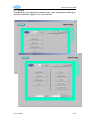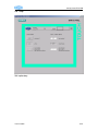
1
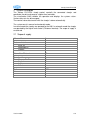
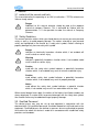
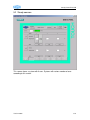
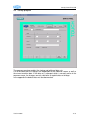
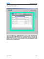
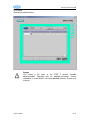
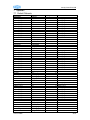
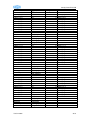
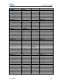
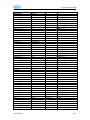
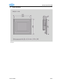
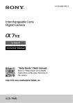
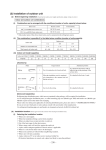
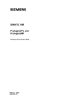
Steady Control PLC/HMI
User Manual
Vollmer Steady Control
PLC/HMI
Version 18964
1/31
Steady Control PLC/HMI
1 Index
1
2
3
4
5
6
7
8
Index................................................................................................................................................. 2
System Description .......................................................................................................................... 3
2.1
Scope of supply......................................................................................................................... 3
General............................................................................................................................................. 4
3.1
contents of the manual and limits ............................................................................................. 4
3.2
Safety Guidelines ...................................................................................................................... 4
3.3
Qualified Personnel................................................................................................................... 4
3.4
Intended Use............................................................................................................................. 5
Getting started.................................................................................................................................. 6
4.1
System Start.............................................................................................................................. 6
4.2
Navigation and Operation ......................................................................................................... 6
4.3
Arrangement ............................................................................................................................. 6
Sreens .............................................................................................................................................. 7
5.1
Main menu ................................................................................................................................ 7
5.2
Steady common ........................................................................................................................ 8
5.2.1
Operating conditions .......................................................................................................... 9
5.2.2
Select Axes ...................................................................................................................... 10
5.2.3
State................................................................................................................................. 10
5.2.4
Setpoint setting ................................................................................................................ 10
5.2.5
Navigation setpoint setting............................................................................................... 10
5.2.6
Selection roll set and actual roll set ................................................................................. 10
5.2.7
Roll set name ................................................................................................................... 10
5.2.8
Hand forward ................................................................................................................... 10
5.3
Steady program....................................................................................................................... 11
5.3.1
Select Data Set ................................................................................................................ 12
5.3.2
Edit and savings............................................................................................................... 12
5.3.3
Delete............................................................................................................................... 12
5.3.4
Save Date ........................................................................................................................ 12
5.4
Steady state ............................................................................................................................ 13
5.5
VSS ......................................................................................................................................... 14
5.5.1
Operating mode ............................................................................................................... 14
5.5.2
Measuring ........................................................................................................................ 14
5.5.3
Calibrate........................................................................................................................... 14
5.6
Faultmessage.......................................................................................................................... 15
5.7
System .................................................................................................................................... 16
5.7.1
Calibrate Touch screen.................................................................................................... 17
5.7.2
Clean Touch..................................................................................................................... 17
5.7.3
Change language............................................................................................................. 17
5.7.4
Help.................................................................................................................................. 17
5.7.5
Status Variable................................................................................................................. 18
5.7.6
Operating System ............................................................................................................ 18
5.7.7
Transfer............................................................................................................................ 18
5.7.8
Synchronize Time ............................................................................................................ 18
5.7.9
User Management ........................................................................................................... 18
5.7.10 Log On/Off User............................................................................................................... 18
5.7.11 Date / Time ...................................................................................................................... 18
5.8
Help ......................................................................................................................................... 19
5.9
User administration ................................................................................................................. 20
5.10 State ........................................................................................................................................ 21
Customer Interface......................................................................................................................... 22
6.1
Statesignals (VollmerCustomer).......................................................................................... 22
6.2
Controlsignals (CustomerVollmer) ...................................................................................... 23
Appendix ........................................................................................................................................ 24
7.1
Default Datasets...................................................................................................................... 24
7.2
Scale drawing.......................................................................................................................... 29
Notes .............................................................................................................................................. 30
Version 18964
2/31
Steady Control PLC/HMI
2 System Description
The Vollmer PLC/VISU steady control, controlls the connected steadys and
coordinate the data exchange to a higher level controller.
The visualization (HMI) enables the operation and displays the systems status.
Various data sets can be managed.
The nominal value data transfer with the steadys is done automatically.
The system consists manual and automatic mode.
In manual mode the steadys are operated by the HMI. In automatic mode the steadys
are operated by the higher level control (Customer Interface). The scope of supply is
customised.
2.1 Scope of supply
Achsen /Axes
Customerinterface
Basic I/O
Advanced I/O
Profibus
Datensätze / Dataset
Sprachen / Languages
German
Englisch
Italy
French
Optionen
Version 18964
6
x
15
X
X
VSS
3/31
Steady Control PLC/HMI
3 General
3.1 contents of the manual and limits
This manual describe the operating of an HMI (visualization / TP270) related to an
Vollmer steady control
Danger
Additional to this manual attention should by paid to the producer
manual of company Siemens. This is delivered by Vollmer with the
documentation. It is also possible to order the manual at Company
Siemens.
3.2 Safety Guidelines
This manual contains notices which you should observe to ensure your own personal
safety as well as to avoid property damage. The notices referring to your personal
safety are highlighted in the manual by a safety alert symbol, notices referring to
property damage only have no safety alert symbol.
Danger
indicates an imminently hazardous situation which, if not avoided, will
result in death or serious injury.
Warning
indicates a potentially hazardous situation which, if not avoided, could
result in death or serious injury.
Caution
used with the safety alert symbol indicates a potentially hazardous
situation which, if not avoided, may result in minor or moderate injury.
Caution
used without safety alert symbol indicates a potentially hazardous
situation which, if not avoided, may result in property damage.
Notice
used without the safety alert symbol indicates a potential situation
which, if not avoided, may result in an undesirable result or state.
When several danger levels apply, the notices of the highest level (lower number) are
always displayed. If a notice refers to personal damages with the safety alert symbol,
then another notice may be added warning of property damage.
3.3 Qualified Personnel
The device/system may only be set up and operated in conjunction with this
documentation. Only qualified personnel should be allowed to install and work on the
equipment. Qualified persons are defined as persons who are authorized to operate
the machine for whom this device is made for in accordance with established safety
practices and standards.
Version 18964
4/31
Steady Control PLC/HMI
3.4 Intended Use
Please note the following:
Warning
This device and its components may only be used for the applications
described in this technical description.
This product can only function correctly and safely if it is transported,
stored, set up and installed correctly, and operated and maintained as
recommended.
Version 18964
5/31
Steady Control PLC/HMI
4 Getting started
4.1 System Start
After switch on the HMI (TP270) starts automatically. The runtime software is started
and a connection to the PLC is generated. The HMI displays the start up screen.
4.2 Navigation and Operation
The display is separated in three ranges.
The header (as described in the navigation) displays left side next to the Vollmer logo
date and time (system time of the TP270). Please also view the description of time
settings and synchronize with the PLC. The display name is shown in the middle of
the header. On the right side there are three function keys for navigation.
The footer (as described in the navigation) consists of eight function keys, which
enables certain functions depending on the range that is currently being used.
The middle of the screen is predominantly for the in- and output elements.
4.3 Arrangement
See screen „help“
Version 18964
6/31
Steady Control PLC/HMI
5 Sreens
5.1 Main menu
The main menu enables navigation and to quit indicated fault messages.
Version 18964
7/31
Steady Control PLC/HMI
5.2 Steady common
This screen shows a system with 6 axes. Systems with various number of axes
according to this screen.
Version 18964
8/31
Steady Control PLC/HMI
5.2.1 Operating conditions
The operation of the system works in conjunction with the status of the settings (i.e.
automatic or manual mode). The following chart shows the coherence, whereby all
conditions have to be fulfilled.
Adjust
off
Service
Start
Stop
Axes
back
Roll set
change
Store
Reset
1
1
1
x
1
1
1
x
0
x
0
x
x
x
x
1
x
1
x
x
x
x
x
Hand
Service
Release
Steadys
x
Forward
0=off; 1=on; x=irrrelevant
5.2.1.1Adjust off
On/Off
5.2.1.2Service
On/Off
5.2.1.3Start
Starts the movement of the axis.
5.2.1.4Stop
Stops all axis.
5.2.1.5Axes back
Starts the movement back.
5.2.1.6Roll set change
Initializes a roll change.
5.2.1.7Store
Saves all the current data permanently to the selected data set.
5.2.1.8Reset
Operated by administrators.
Notice
Hardware reset of the axis.
Version 18964
9/31
Steady Control PLC/HMI
5.2.2 Select Axes
Enables movements with or without horizontal or vertical axis.
5.2.3 State
Displays the status of an axis as a short message. Detailed information can be found
in the „Status“ sreen.
5.2.4 Setpoint setting
Can be operated when the preset data set is currently being used.
Enables the nominal size preset in one (1) percent (%) steps. Nominal size changes
are directly taken over.
5.2.5 Navigation setpoint setting
By clicking the nominal size display, the operating keys move to the “Nominal Size
Presets „ and to their respective axis.
5.2.6 Selection roll set and actual roll set
Operated in the manual mode.
In the automatic mode the customer interface makes the selection.
The selection of the roll set is done via the selection field „Roll Set“. The taking over
is completed by activating „Roll Change“. The new roll set is then displayed as
„Current“.
5.2.7 Roll set name
The roll set name is displayed in the „Name“ field.
5.2.8 Hand forward
Operated in service mode.
Starts the movements forward of a single axis.
Version 18964
10/31
Steady Control PLC/HMI
5.3 Steady program
The program overview enables the viewing and editing of data sets.
It is to be noted that the settings are independent of the common screen as well as
the current machine data. If the data set is changed, which is currently active in the
common screen, the changes are only valid after an explicit data set change.
In the appendix the default data sets are documented.
Version 18964
11/31
Steady Control PLC/HMI
5.3.1 Select Data Set
The selection can be done in the selection field „Roll Set No.“ or using the „<“ and „>“
keys.
5.3.2 Edit and savings
If a data set has to be changed, it can be done by selecting „Edit“. Nominal values
can be selected in steps of one (1) percent (%). In the field „Roll set Name“ texts
having a length of up to 40 characters and in the field „Comments“ up to 80
characters can be made.
The data set is permanently stored when selecting „Save“.
5.3.3 Delete
Intialise the data set with the default value 0.
5.3.4 Save Date
With the command „Save“ or „Delete“ the current system time is used as the save
date.
Version 18964
12/31
Steady Control PLC/HMI
5.4 Steady state
”Status“ provides an overview of the current system status. A fault message is
displayed in the status window as a blinking button „Fault Message“ in the lower right
corner of the screen. The fault can be viewed or exited by selecting the „Fault
Message“ screen.
Version 18964
13/31
Steady Control PLC/HMI
5.5 VSS
5.5.1 Operating mode
As command source for operating the TP270 (HMI) or the customer interface can be
selected. The selection is shown by the statedisplay.
5.5.2 Measuring
Operated by HMI mode
The measuring can be switched on or off. The state is shown in the display. Enable
the measuring also possible if the measuring device is not calibrated.
5.5.3 Calibrate
Operated by HMI mode
Starts the calibration mode the state is shown in display.
If the check time is exceed and the check back signal is not recieved a fault message
is displayed.
Version 18964
14/31
Steady Control PLC/HMI
5.6 Faultmessage
„Fault Message“ provides an overview of the current faults. A current fault can be quit
by pressing the „Quit Fault“ button.
Version 18964
15/31
Steady Control PLC/HMI
5.7 System
Is designed for further operations of administrators. Upon having administrator rights,
selections and buttons appear in the system window.
Version 18964
16/31
Steady Control PLC/HMI
5.7.1 Calibrate Touch screen
Depending on the installation position and viewing angle, it is possible that a more or
less strong parallax may occur when operating the touch panel screen. In order to
prevent resulting operating errors, the screen can be calibrated during the start-up
phase and normal operation.
1. Open the "Calibrate Touch"" dialog.
2. Five calibration crosses appear in succession on the screen. Follow the
instructions provided on the screen and touch the respective calibration cross.
3. To apply the new calibration:
Touch any point on the screen after the calibration process for the new calibration
data to take effect.
4. To discard the new calibration: Wait 30 seconds (until the counter reaches zero)
before rejecting the new calibration data.
If calibration is not performed correctly, the new values are not accepted.
Warning
During calibration it is not possible to operate the HMI. The control must
be in a safe state before starting the calibration.
5.7.2 Clean Touch
The HMI can be cleaned when switched on and when operating normally if
touchscreen input has been suppressed by means of an appropriately configured
operating element (Clean Screen). After the Clean Screen function has been
activated, all input via the touchscreen operating elements is deactivated for a
defined period of time. The time remaining until the end of operating suppression is
indicated by a progress bar.
Warning
During cleaning it is not possible to operate the HMI. The control must
be in a safe state before starting the calibration.
Suppressing operating elements Only clean the screen during operation
when Clean Screen is activated. Note the end of operating suppression
by the Clean Screen. Otherwise, incorrect operations may be initiated.
5.7.3 Change language
Various languages are stored within the system and can be selected by pressing the
„Change Language“ button. After pressing the button numerous times the original
language appears again.
5.7.4 Help
Selection of the help system.
Version 18964
17/31
Steady Control PLC/HMI
5.7.5 Status Variable
Operated by administrators.
Selection window „Status Variable“
5.7.6 Operating System
Operated by administrators.
This function enables to switch to the operating system. A detailed description can be
found in the WinCC documentation.
Warning
If the HMI is changed to the operating system it is not possible to
operate the HMI. The control must be in a safe state before starting the
calibration.
5.7.7 Transfer
Operated by administrators.
The transfer function switches the system to the transfer mode. A detailed description
can be found in the WinCC documentation.
Warning
If the HMI is in the transfer mode it is not possible to operate the HMI.
The control must be in a safe state before starting the calibration.
5.7.8 Synchronize Time
Operated by administrators.
The system time of the HMI and the PLC are hereby synchronized. The PLC is
presetted with the system time of the HMI.
5.7.9 User Management
Operated by administrators.
Selection screen „User Management“
5.7.10
Log On/Off User
It is possible to log on/off users with the system. This is required due to the fact that it
is necessary to generate higher level operating rights. The operator and password
entry is to be acknowledged with the return key. Logging on and off is done by
pressing the corresponding button.
5.7.11
Date / Time
In the navigation it is possible to change the date and time. Entries are to be
acknowledged by pressing the return key. If the format is not correctly inputted , the
old data is further used.
Version 18964
18/31
Steady Control PLC/HMI
5.8 Help
Self explanatory
Version 18964
19/31
Steady Control PLC/HMI
5.9 User administration
Operated by administrators.
The user management is a standard application of WinCC flexible. With administrator
rights, it is possible to add additional users. The general operation of the HMI is also
possible without any rights. Functions that require rights have been explained and
marked in the user manual. Further information of the user management can be
found in the WinCC flexible manual.
Version 18964
20/31
Steady Control PLC/HMI
5.10 State
Operated by administrators.
Danger
This screen is the same as the STEP 7 function „Variable
observe/control“. Operation only via qualified personnel. Further
information is to be found in the corresponding Siemens System user
manuals.
Version 18964
21/31
Steady Control PLC/HMI
6 Customer Interface
6.1 Statesignals (VollmerCustomer)
Adresse
A
6.0
A
6.1
A
6.2
A
6.3
A
6.4
A
6.5
A
6.6
A
6.7
A
7.0
A
7.1
A
7.2
A
7.3
A
7.4
A
7.5
A
7.6
A
7.7
Datentyp
BOOL
BOOL
BOOL
BOOL
BOOL
BOOL
BOOL
BOOL
BOOL
BOOL
BOOL
BOOL
BOOL
BOOL
BOOL
BOOL
Version 18964
Signal
Lünette 1 horiz. hintere Endlage / steady 1 horizontal rear limitposition
Lünette 1 horiz. in Position / steady 1 horizontal in position
Lünette 1 vertik. hintere Endlage / steady 1 vertical rear limitposition
Lünette 1 vertik. in Position / steady 1 vertical in position
Lünette 2 horiz. hintere Endlage / steady 2 horizontal rear limitposition
Lünette 2 horiz. in Position / steady 2 horizontal in position
Lünette 2 vertik. hintere Endlage / steady 2 vertical rear limitposition
Lünette 2 vertik. in Position / steady 2 vertical in position
Lünette 3 horiz. hintere Endlage / steady 3 horizontal rear limitposition
Lünette 3 horiz. in Position / steady 3 horizontal in position
Lünette 3 vertik. hintere Endlage / steady 3 vertical rear limitposition
Lünette 3 vertik. in Position / steady 3 vertical in position
Freigabe / ackknowlegde
Lünetten in Service / steadys in service
VSS kalibrieren / VSS calibrate
VSS Messung ein / VSS measuring on
22/31
Steady Control PLC/HMI
6.2 Controlsignals (CustomerVollmer)
Adresse
E
5.0
E
5.1
E
5.2
E
5.3
E
5.4
E
5.5
E
5.6
E
5.7
E
6.0
E
6.1
E
6.2
E
6.3
E
6.4
E
6.5
E
6.6
E
6.7
E
7.0
Datentyp
BOOL
BOOL
BOOL
BOOL
BOOL
BOOL
BOOL
BOOL
BOOL
BOOL
BOOL
BOOL
BOOL
BOOL
BOOL
BOOL
BOOL
Version 18964
Signal
Vor Lünetten 1-5 / forward steady 1-5
Zurück Lünetten 1-5 / backward steady 1-5
Umkehrpunkt links / turnaround left
Umkehrpunkt rechts / turnaround right
Stop / stop
Daten gültig / data ok
Automatik / auto
Datensatz Bit 0 / select datarecord bit 0
Datensatz Bit 1 / select datarecord bit 1
Datensatz Bit 2 / select datarecord bit 2
Datensatz Bit 3 / select datarecord bit 3
Reserve
Reserve
Reserve
VSS Messen Ein / Aus
VSS Kalibrierwert setzen
VSS Ist Kalibriert
23/31
Steady Control PLC/HMI
7 Appendix
7.1 Default Datasets
Name
Datensatz1
Sollwert_L1_H
Sollwert_L1_V
Sollwert_L2_H
Sollwert_L2_V
Sollwert_L3_H
Sollwert_L3_V
Sollwert_L4_H
Sollwert_L4_V
Sollwert_L5_H
Sollwert_L5_V
Datum
Uhrzeit
Reserve
Walzentyp
Bemerkung
Datensatz2
Sollwert_L1_H
Sollwert_L1_V
Sollwert_L2_H
Sollwert_L2_V
Sollwert_L3_H
Sollwert_L3_V
Sollwert_L4_H
Sollwert_L4_V
Sollwert_L5_H
Sollwert_L5_V
Datum
Uhrzeit
Reserve
Walzentyp
Bemerkung
Datensatz3
Sollwert_L1_H
Sollwert_L1_V
Sollwert_L2_H
Sollwert_L2_V
Sollwert_L3_H
Sollwert_L3_V
Sollwert_L4_H
Sollwert_L4_V
Sollwert_L5_H
Sollwert_L5_V
Datum
Uhrzeit
Reserve
Walzentyp
Bemerkung
Version 18964
Typ
STRUCT
INT
INT
INT
INT
INT
INT
INT
INT
INT
INT
DATE
TIME_OF_DAY
INT
STRING[40]
STRING[80]
END_STRUCT
STRUCT
INT
INT
INT
INT
INT
INT
INT
INT
INT
INT
DATE
TIME_OF_DAY
INT
STRING[40]
STRING[80]
END_STRUCT
STRUCT
INT
INT
INT
INT
INT
INT
INT
INT
INT
INT
DATE
TIME_OF_DAY
INT
STRING[40]
STRING[80]
END_STRUCT
Anfangswert
D#1990-1-1
TOD#0:0:0.0
Kommentar
2 Sollwert_L1_H
2 Sollwert_L1_V
2 Sollwert_L2_H
2 Sollwert_L2_V
2 Sollwert_L3_H
2 Sollwert_L3_V
2 Sollwert_L4_H
2 Sollwert_L4_V
2 Sollwert_L5_H
2 Sollwert_L5_V
Datum
Uhrzeit
0
''
''
D#1990-1-1
TOD#0:0:0.0
2 Sollwert_L1_H
2 Sollwert_L1_V
2 Sollwert_L2_H
2 Sollwert_L2_V
2 Sollwert_L3_H
2 Sollwert_L3_V
2 Sollwert_L4_H
2 Sollwert_L4_V
2 Sollwert_L5_H
2 Sollwert_L5_V
Datum
Uhrzeit
0
''
''
D#1990-1-1
TOD#0:0:0.0
2 Sollwert_L1_H
2 Sollwert_L1_V
2 Sollwert_L2_H
2 Sollwert_L2_V
2 Sollwert_L3_H
2 Sollwert_L3_V
2 Sollwert_L4_H
2 Sollwert_L4_V
2 Sollwert_L5_H
2 Sollwert_L5_V
Datum
Uhrzeit
0
''
''
24/31
Steady Control PLC/HMI
Name
Datensatz4
Sollwert_L1_H
Sollwert_L1_V
Sollwert_L2_H
Sollwert_L2_V
Sollwert_L3_H
Sollwert_L3_V
Sollwert_L4_H
Sollwert_L4_V
Sollwert_L5_H
Sollwert_L5_V
Datum
Uhrzeit
Reserve
Walzentyp
Bemerkung
Datensatz5
Sollwert_L1_H
Sollwert_L1_V
Sollwert_L2_H
Sollwert_L2_V
Sollwert_L3_H
Sollwert_L3_V
Sollwert_L4_H
Sollwert_L4_V
Sollwert_L5_H
Sollwert_L5_V
Datum
Uhrzeit
Reserve
Walzentyp
Bemerkung
Datensatz6
Sollwert_L1_H
Sollwert_L1_V
Sollwert_L2_H
Sollwert_L2_V
Sollwert_L3_H
Sollwert_L3_V
Sollwert_L4_H
Sollwert_L4_V
Sollwert_L5_H
Sollwert_L5_V
Datum
Uhrzeit
Reserve
Walzentyp
Bemerkung
Version 18964
Typ
STRUCT
INT
INT
INT
INT
INT
INT
INT
INT
INT
INT
DATE
TIME_OF_DAY
INT
STRING[40]
STRING[80]
END_STRUCT
STRUCT
INT
INT
INT
INT
INT
INT
INT
INT
INT
INT
DATE
TIME_OF_DAY
INT
STRING[40]
STRING[80]
END_STRUCT
STRUCT
INT
INT
INT
INT
INT
INT
INT
INT
INT
INT
DATE
TIME_OF_DAY
INT
STRING[40]
STRING[80]
END_STRUCT
Anfangswert
D#1990-1-1
TOD#0:0:0.0
Kommentar
2 Sollwert_L1_H
2 Sollwert_L1_V
2 Sollwert_L2_H
2 Sollwert_L2_V
2 Sollwert_L3_H
2 Sollwert_L3_V
2 Sollwert_L4_H
2 Sollwert_L4_V
2 Sollwert_L5_H
2 Sollwert_L5_V
Datum
Uhrzeit
0
''
''
D#1990-1-1
TOD#0:0:0.0
0 Sollwert_L1_H
2 Sollwert_L1_V
2 Sollwert_L2_H
2 Sollwert_L2_V
2 Sollwert_L3_H
2 Sollwert_L3_V
2 Sollwert_L4_H
2 Sollwert_L4_V
2 Sollwert_L5_H
2 Sollwert_L5_V
Datum
Uhrzeit
0
''
''
D#1990-1-1
TOD#0:0:0.0
2 Sollwert_L1_H
2 Sollwert_L1_V
2 Sollwert_L2_H
2 Sollwert_L2_V
2 Sollwert_L3_H
2 Sollwert_L3_V
2 Sollwert_L4_H
2 Sollwert_L4_V
2 Sollwert_L5_H
2 Sollwert_L5_V
Datum
Uhrzeit
0
''
''
25/31
Steady Control PLC/HMI
Name
Datensatz7
Sollwert_L1_H
Sollwert_L1_V
Sollwert_L2_H
Sollwert_L2_V
Sollwert_L3_H
Sollwert_L3_V
Sollwert_L4_H
Sollwert_L4_V
Sollwert_L5_H
Sollwert_L5_V
Datum
Uhrzeit
Reserve
Walzentyp
Bemerkung
Datensatz8
Sollwert_L1_H
Sollwert_L1_V
Sollwert_L2_H
Sollwert_L2_V
Sollwert_L3_H
Sollwert_L3_V
Sollwert_L4_H
Sollwert_L4_V
Sollwert_L5_H
Sollwert_L5_V
Speicherdatum
Walzentyp
Bemerkung
Datensatz9
Sollwert_L1_H
Sollwert_L1_V
Sollwert_L2_H
Sollwert_L2_V
Sollwert_L3_H
Sollwert_L3_V
Sollwert_L4_H
Sollwert_L4_V
Sollwert_L5_H
Sollwert_L5_V
Datum
Uhrzeit
Reserve
Walzentyp
Bemerkung
Version 18964
Typ
STRUCT
INT
INT
INT
INT
INT
INT
INT
INT
INT
INT
DATE
TIME_OF_DAY
INT
STRING[40]
STRING[80]
END_STRUCT
STRUCT
INT
INT
INT
INT
INT
INT
INT
INT
INT
INT
DATE_AND_TIME
STRING[40]
STRING[80]
END_STRUCT
STRUCT
INT
INT
INT
INT
INT
INT
INT
INT
INT
INT
DATE
TIME_OF_DAY
INT
STRING[40]
STRING[80]
END_STRUCT
Anfangswert
D#1990-1-1
TOD#0:0:0.0
Kommentar
2 Sollwert_L1_H
2 Sollwert_L1_V
2 Sollwert_L2_H
2 Sollwert_L2_V
2 Sollwert_L3_H
2 Sollwert_L3_V
2 Sollwert_L4_H
2 Sollwert_L4_V
2 Sollwert_L5_H
2 Sollwert_L5_V
Datum
Uhrzeit
0
''
''
DT#90-1-10:0:0.000
''
''
D#1990-1-1
TOD#0:0:0.0
2 Sollwert_L1_H
2 Sollwert_L1_V
2 Sollwert_L2_H
2 Sollwert_L2_V
2 Sollwert_L3_H
2 Sollwert_L3_V
2 Sollwert_L4_H
2 Sollwert_L4_V
2 Sollwert_L5_H
2 Sollwert_L5_V
Speicherdatum
2 Sollwert_L1_H
2 Sollwert_L1_V
2 Sollwert_L2_H
2 Sollwert_L2_V
2 Sollwert_L3_H
2 Sollwert_L3_V
2 Sollwert_L4_H
2 Sollwert_L4_V
2 Sollwert_L5_H
2 Sollwert_L5_V
Datum
Uhrzeit
0
''
''
26/31
Steady Control PLC/HMI
Name
Datensatz10
Sollwert_L1_H
Sollwert_L1_V
Sollwert_L2_H
Sollwert_L2_V
Sollwert_L3_H
Sollwert_L3_V
Sollwert_L4_H
Sollwert_L4_V
Sollwert_L5_H
Sollwert_L5_V
Datum
Uhrzeit
Reserve
Walzentyp
Bemerkung
Datensatz11
Sollwert_L1_H
Sollwert_L1_V
Sollwert_L2_H
Sollwert_L2_V
Sollwert_L3_H
Sollwert_L3_V
Sollwert_L4_H
Sollwert_L4_V
Sollwert_L5_H
Sollwert_L5_V
Datum
Uhrzeit
Reserve
Walzentyp
Bemerkung
Datensatz12
Sollwert_L1_H
Sollwert_L1_V
Sollwert_L2_H
Sollwert_L2_V
Sollwert_L3_H
Sollwert_L3_V
Sollwert_L4_H
Sollwert_L4_V
Sollwert_L5_H
Sollwert_L5_V
Datum
Uhrzeit
Reserve
Walzentyp
Bemerkung
Version 18964
Typ
STRUCT
INT
INT
INT
INT
INT
INT
INT
INT
INT
INT
DATE
TIME_OF_DAY
INT
STRING[40]
STRING[80]
END_STRUCT
STRUCT
INT
INT
INT
INT
INT
INT
INT
INT
INT
INT
DATE
TIME_OF_DAY
INT
STRING[40]
STRING[80]
END_STRUCT
STRUCT
INT
INT
INT
INT
INT
INT
INT
INT
INT
INT
DATE
TIME_OF_DAY
INT
STRING[40]
STRING[80]
END_STRUCT
Anfangswert
D#1990-1-1
TOD#0:0:0.0
Kommentar
2 Sollwert_L1_H
2 Sollwert_L1_V
2 Sollwert_L2_H
2 Sollwert_L2_V
2 Sollwert_L3_H
2 Sollwert_L3_V
2 Sollwert_L4_H
2 Sollwert_L4_V
2 Sollwert_L5_H
2 Sollwert_L5_V
Datum
Uhrzeit
0
''
''
D#1990-1-1
TOD#0:0:0.0
2 Sollwert_L1_H
2 Sollwert_L1_V
2 Sollwert_L2_H
2 Sollwert_L2_V
2 Sollwert_L3_H
2 Sollwert_L3_V
2 Sollwert_L4_H
2 Sollwert_L4_V
2 Sollwert_L5_H
2 Sollwert_L5_V
Datum
Uhrzeit
0
''
''
D#1990-1-1
TOD#0:0:0.0
2 Sollwert_L1_H
2 Sollwert_L1_V
2 Sollwert_L2_H
2 Sollwert_L2_V
2 Sollwert_L3_H
2 Sollwert_L3_V
2 Sollwert_L4_H
2 Sollwert_L4_V
2 Sollwert_L5_H
2 Sollwert_L5_V
Datum
Uhrzeit
0
''
''
27/31
Steady Control PLC/HMI
Name
Datensatz13
Sollwert_L1_H
Sollwert_L1_V
Sollwert_L2_H
Sollwert_L2_V
Sollwert_L3_H
Sollwert_L3_V
Sollwert_L4_H
Sollwert_L4_V
Sollwert_L5_H
Sollwert_L5_V
Datum
Uhrzeit
Reserve
Walzentyp
Bemerkung
Datensatz14
Sollwert_L1_H
Sollwert_L1_V
Sollwert_L2_H
Sollwert_L2_V
Sollwert_L3_H
Sollwert_L3_V
Sollwert_L4_H
Sollwert_L4_V
Sollwert_L5_H
Sollwert_L5_V
Datum
Uhrzeit
Reserve
Walzentyp
Bemerkung
Datensatz15
Sollwert_L1_H
Sollwert_L1_V
Sollwert_L2_H
Sollwert_L2_V
Sollwert_L3_H
Sollwert_L3_V
Sollwert_L4_H
Sollwert_L4_V
Sollwert_L5_H
Sollwert_L5_V
Datum
Uhrzeit
Reserve
Walzentyp
Bemerkung
Version 18964
Typ
STRUCT
INT
INT
INT
INT
INT
INT
INT
INT
INT
INT
DATE
TIME_OF_DAY
INT
STRING[40]
STRING[80]
END_STRUCT
STRUCT
INT
INT
INT
INT
INT
INT
INT
INT
INT
INT
DATE
TIME_OF_DAY
INT
STRING[40]
STRING[80]
END_STRUCT
STRUCT
INT
INT
INT
INT
INT
INT
INT
INT
INT
INT
DATE
TIME_OF_DAY
INT
STRING[40]
STRING[80]
END_STRUCT
Anfangswert
Kommentar
2
2
2
2
2
2
2
2
2
2
D#1990-1-1
TOD#0:0:0.0
Sollwert_L1_H
Sollwert_L1_V
Sollwert_L2_H
Sollwert_L2_V
Sollwert_L3_H
Sollwert_L3_V
Sollwert_L4_H
Sollwert_L4_V
Sollwert_L5_H
Sollwert_L5_V
Datum
Uhrzeit
0
''
''
2
2
2
2
2
2
2
2
2
2
D#1990-1-1
TOD#0:0:0.0
Sollwert_L1_H
Sollwert_L1_V
Sollwert_L2_H
Sollwert_L2_V
Sollwert_L3_H
Sollwert_L3_V
Sollwert_L4_H
Sollwert_L4_V
Sollwert_L5_H
Sollwert_L5_V
Datum
Uhrzeit
0
''
''
2
2
2
2
2
2
2
2
2
2
D#1990-1-1
TOD#0:0:0.0
Sollwert_L1_H
Sollwert_L1_V
Sollwert_L2_H
Sollwert_L2_V
Sollwert_L3_H
Sollwert_L3_V
Sollwert_L4_H
Sollwert_L4_V
Sollwert_L5_H
Sollwert_L5_V
Datum
Uhrzeit
0
''
''
28/31
Steady Control PLC/HMI
7.2 Scale drawing
Version 18964
29/31
Steady Control PLC/HMI
8 Notes
Version 18964
30/31
Steady Control PLC/HMI
Version 18964
31/31