1
`
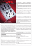
Natural Speech & Complex Sound Synthesizer
User’s Manual
September 17, 2004
Revision 1.1
Copyright 2004 Magnevation LLC, All rights reserved
Core Features:
RC1 / E7
RC0 / E6
E5
E4
Gnd
E3
E2
E1
E0
VOut
D0 / Ready
•
•
•
•
•
•
•
•
•
•
•
•
•
•
D1 / Speaking
D2 / Buffer Half Full
V+
M0
M1
Rst
RCX
Programmable, 5 channel synthesizer.
Natural phonetic speech synthesis.
DTMF and other sound effects.
Programmable control of pitch, rate, bend and volume.
Programmable power – up or reset announcements.
Multiple modes of operation.
Simple interface to microcontrollers.
Simple “Stand Alone” operation.
Three programmable digital outputs.
Internal 64 Byte input buffer.
Internal programmable EEPROM.
Extremely low power consumption.
Low pin count.
Multiple case styles available.
Special Features
General Description
•
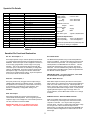
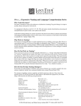
The SpeakJet is a completely self contained, single
chip voice and complex sound synthesizer. SpeakJet
uses Mathematical Sound Architecture tm (MSA)
technology which controls an internal five channel
sound synthesizer to generate on-the-fly, unlimited
vocabulary speech synthesis and complex sounds
without the use of analog or digitally recorded samples.
The SpeakJet has a built in library of 72 speech
elements (allophones), 43 sound effects, and 12 DTMF
Touch Tones. Through the selection of these MSA
components and in combination with the control of the
pitch, rate, bend, and volume parameters, the user has
the ability to produce unlimited phrases and sound
effects, with thousands of variations, at any time.
•
•
•
•
Three multipurpose, programmable digital outputs allow
the SpeakJet to control external devices based on
timing of the sound output. Control of devices may
include lights, motors, or even launch model rocket after
a count down sequence.
An internal clock oscillator provides for a truly “Self
Contained sound system. Simply connect the SpeakJet
to a power supply and a speaker to hear it speak. *
An internal user programmable EEPROM allows for
programming of up to 16 complex phrases or sound
sequences. These may be played back once or looped
many times in response to events.
Phrases may call other phrases, sounds or controls,
with nesting up to 3 levels deep.
No special equipment is required to program the internal
EEPROM, only a serial connection is required.
Interface Options
The SpeakJet can be controlled simultaneously by logic
changes on any one of its eight Event Input lines,
and/or by a Serial Data line from a CPU (such as the
OOPic, Basic Stamp or PC) allowing for both CPUControlled and Stand-Alone operations.
•
•
Other features include an internal 64 byte input buffer,
Internal Programmable EEPROM, three programmable
outputs, and direct user access to the internal five
channel sound synthesizer.
•
More information can be found at www.SpeakJet.com
1
CPU Control: Single Wire Serial Input from
microprocessors such as the OOPic, Basic Stamp, or any
other computer system equipped with a serial port.
Stand Alone: Eight Event Inputs for execution of up to
sixteen phrases, sound effects or control functions with or
without a microcontroller.
RC Input: Two Servo Pulse Inputs for execution of up to
four phrases, sound effects or control functions via
wireless model Airplane or Car Radio Control receivers.
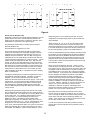
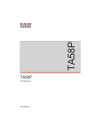
SpeakJet Pin Details
Pin #
1
2
3
4
5
6
7
8
9
10
11
12
13
14
15
16
17
18
Description
RC1/E7
RC0/E6
E5
E4
Gnd
E3
E2
E1
E0
RCX
Rst
M1
M0
V+
D2/Buffer Half Full
D1/Speaking
D0/Ready
VOut
Functional Details
Event Input 7
Event Input 6
Event Input 5
Event Input 4
Ground
Event Input 3
Event Input 2
Event Input 1
Event Input 0
Serial Input TTL (0.0v to Vcc)
Master Reset
Mode Select 1 (Baud Configure)
Mode Select 0 (Demo Mode)
Power input +2.0 to +5.5 volts DC
Data Out 2 (External) / Buffer Half Full (Internal)
Data Out 1 (External) / Speaking (Internal)
Data Out 0 (External) / Ready (Internal)
Voice Output
Electrical Specifications:
Supply voltage
2.0 to 5.5 VDC
Supply Current:
Idle:
<5ma. Plus loads
Speaking:
<5ma. Plus loads
Sink/Source Current:
Outputs
All Inputs levels:
High
Low
EEPROM:
Max. Write cycles
25ma.
Supply
GND
Typical 1,000,000 times
Mechanical Specification:
Thermal storage:
-60 to +140 Degrees C
Thermal operating
-18 to +60 Degrees C
The thermal specifications are preliminary and
may change as testing is completed.
Table A
SpeakJet Pin Functional Explanation
E0 – E7 : Event Input 0 – 7
Rst : Master Reset
Event Inputs provide a way to execute phrases, sound effects
or control functions that have been pre-programmed into the
EEPROM. Each Event Input can be configured to activate on
a Low to High going transition, and/or a High to Low going
transition. This can be combined to allow two Events with
one Event Input. This feature is controlled by a configuration
setting in the EEPROM. The Event Inputs are logical inputs
that require a High or Low logic level and two of the Event
Inputs can be configured as RC inputs. Any Event Input that
is not used, must be connected to GND
The Master Reset provides a way to reset the SpeakJet to
power up conditions. This forces the internal control circuit to
reset and clear the input buffer. The configuration bits and
stored phrases in the EEPROM are not affected. This is a
logical input that requires a High or Low logic level and is
active low. The use of RESET along with the logic states of
the Mode Select inputs M0 and M1, places the SpeakJet into
the different modes of operation.
IMPORTANT NOTE: For normal operation, “Rst” must
be connected to V+ through a resistor.
RC0, RC1 : Event Input 6, 7
M0, M1 : Mode Select 0, 1
RC inputs provide a way to trigger an Event Inputs using a
variable width pulse from a model RC receiver. This allows
the SpeakJet to be controlled by a remote link to execute up
to four phrases, sound effects or control functions. This
feature is controlled by a configuration setting in the
EEPROM.
Mode Select inputs are read by the internal control system
after a power-up or a reset is forced, and is used to determine
which one of two modes to start up in: Normal Operation or
Demo / Test mode. When in Demo / Test mode the SpeakJet
can be placed in Baud Rate Configure mode. These pins are
logical inputs that require a High or Low logic level. For
normal operation, connect M0 to GND. and M1 to V+ through
a resistor.
RCX : Serial Input
D2/Buffer Half Full : Data Out 2/Buffer Half Full
Serial Input provides the means for external devices to
communicate with the SpeakJet. This is a logical input that
requires a High or Low voltage level. If the Serial Input line is
not used, it must be connected to GND.
Data Out 2 / Buffer Half Full output is used for flow control
with a serial port by connecting to the CTS line back to the
computer or controller. Or it may be used as a generalpurpose output. This line is a logical output with either a High
or Low logic level. Which function this output uses is
determined by a configuration bit stored in the EEPROM and
the factory default configurations is: “Buffer Half Full” and is
Active High.
IMPORTANT NOTE: This is not RS-232 signal level
voltages. See section on RS-232 for more details.
2
D1 / Speaking : Data Out 1 / Speaking
General Operation:
Data Out 1 / Speaking output is used to indicate when the
SpeakJet is “Speaking”. Or it may be used as a generalpurpose output. This line is a logical output with either a High
or Low logic level. Which function this output uses is
determined by a configuration bit stored in the EEPROM and
the factory default configurations is: “Speaking” and is Active
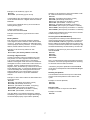
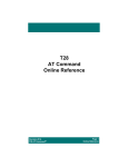
The SpeakJet is an advanced CMOS LSI device that
incorporates six basic internal modules: (Figure 2)
•
•
•
D0 / Ready : Data Out 0 / Ready
•
•
•
Data Out 0 / Ready output is used to indicate when the
SpeakJet is Ready. This indicates that the internal self-test
has passed and the Speakjet is ready to accept data through
one of its inputs. Or it may be used as a general-purpose
output. This line is a logical output with either a High or Low
logic level. Which function this output uses is determined by
a configuration bit stored in the EEPROM and the factory
default configurations is: “Ready” and is Active High.
5-Channel Synthesizer. For generating both voice and
sound effects.
Mathematical Sound Architecture tm (MSA) engine and
Sound Component Database that controls the 5Channel Synthesizer.
Chip control I/O, which consists of 1Serial Input, 8
Event Inputs, 3 Data Outputs, and 2 Mode Select
inputs and Reset.
64-Byte Input Buffer.
User EEPROM.
A Serial Control Protocol (SCP), which supervises the
incoming serial commands.
When powered on, the SpeakJet will first read the Mode Select
line M0 to determine if the SpeakJet is to operate in
Demonstration Mode. Once the Initial Mode is set, (note that
this only occurs at power-up or reset) the input buffer is cleared,
the status lines are set, D0 / Ready is brought high and the
SpeakJet begins operating.
Vout : Voice Output
During operation, the Serial Port waits for incoming command
data, which specifies which sounds and effects the MSA is to
direct the 5 channel synthesizer to produce.
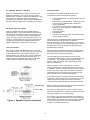
Voice Output modulates the SpeakJet’s voice on a square
wave carrier of 32 khz. The duty cycle of this carrier is varied
by the modulation of the sound output. This duty cycles
typically varies by 70% and can vary up to 100% depending
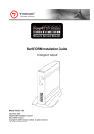
on the level of output represented by the audio wave. A
simple “two pole” low pass filter (see Figure 1) is all that is
required before an amplifier to obtain quality sound.
The commands sent to the SpeakJet can be any of 256
commands (See Table D & E). There are 7 operational groups
of commands. SCP, Allophones, Sound Effects, DTMF,
Pauses, Levels and Controls. Each operational group will
behave in different ways.
With the exception of SCP commands, each command
received, is buffered into a 64-Byte input buffer and executed
by the MSA in the order that they are received, First In First Out
(FIFO). In the case of SCP, these commands are executed
immediately as they are received and not stored in the input
buffer. See the section on SCP for further details.
As the MSA executes the commands stored in the input buffer,
it directs the 5 Channel Synthesizer, which produces the Voice
output (See Figure2 and Figure 3) and each command is
removed from the input buffer after the command is executed.
Both the Serial Input and the 8 Event Inputs provide methods of
placing command data in the Input Buffer.
Serial Input: A single input line is used to receive command
data at the preset baud rate. The RCX is the serial input and is
expecting a logical level (non-inverted) signal.
Event Inputs: In the case that an Event Input is configured to
do so, a single EEPROM Call command is stored into the input
buffer whenever one of the Event Input’s logic state is changed
or in the case of the RC Event Input, when a PWM pulse
changes to a predetermined amount.
Figure 1. SpeakJet Typical connections
3
Figure 2. SpeakJet Block Diagram
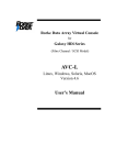
Figure 3. SpeakJet
5 Channel Synthesizer Block Diagram
4
Serial Data:
Status lines provide information on the current operational
status of the SpeakJet.
Serial Data is the main method of communicating with the
SpeakJet to execute commands or create voices and sounds.
The serial data can also be used to program the internal
EEPROM. The SpeakJet does not accept actual RS-232A
signal levels, and will be damaged if attempted to input these
levels. In order to read data from a RS-232A type of serial data
stream, a level shifter/line receiver must be used. This can be
as simple as a small transistor or more robust device like the
MAX232A from Maxim.
“D0 / Ready” is active high when the SpeakJet is on and
ready to accept commands.
“D1 / Speaking” is active high when the SpeakJet is
currently generating any sound.
“D2 / Buffer Half Full” is active high when the input buffer is
1/2 full. This indicates when the 64-Byte input buffer has
more than 32 bytes in it. As the MSA executes the
commands stored in the input buffer, the buffer memory is
freed and as 32 bytes of the buffer becomes available, the
Buffer Half Full output line will reflect that status. This line
can be used in a serial connection as the serial port’s CTS
line. A logical Low output indicates that the buffer can
accept 32 bytes and a logical High output indicates that the
buffer cannot.
The SpeakJet serial configuration is fixed at: 8 bits, No- Parity,
and 1 stop bit (8, N, 1) and non-inverted, (RS-232 is inverted
logic and higher voltages). The Speakjet can be configured to
accept Baud rates from 2400 to 19200. The factory default
setting is 9600 baud. This baud rate can be changed any time
by placing the SpeakJet into the “Baud Rate Configure Mode.
The status lines can also be user programmed to control
external devices. Each Status line can be individually
selected to be and internal Status or user selected logic
state.
Serial Control Protocol (SCP)
In addition to using the serial port to communicate with the MSA
module, the SpeakJet includes a system called the Serial
Control Protocol (SCP), which allows the 5-Channel
Synthesizer and the EEPROM in the SpeakJet to be controlled
over the serial port. More information can be found at
www.openscp.com
Mode Select:
When a High logic level is placed on Mode Select, M0, and
RESET is forced, the SpeakJet starts a Demo mode where all
internal allophones and sound effects are played in a loop.
This loop plays only when the buffer is empty and will
suspend if any data is sent to the buffer. When M0 is brought
back to a low state the demo mode is suspended. If M0 is
brought back to a high state, the demo mode continues from
the point where it was suspended. A RESET with a low logic
level on Mode select M0 will discontinue the Demo/Test
mode and place the SpeakJet back to normal operation.
Overview:
The function of the SpeakJet’s implementation of the Serial
Control Protocol (SCP) is to allow a serially attached device to
interact with the control portion of the SpeakJet. Note that the
entire character set used by SCP is composed of human
readable characters so that a serial terminal program can be
used to manually control the SpeakJet.
Baud Rate Configure:
The SCP module will silently monitor all incoming serial data
that is received by the SpeakJet’s serial port for the Escape
Sequence that activates the Serial Control Mode. When
activated, all serial data is then exchanged with the SCP
module until a future Escape Sequence or End SCP Control
changes the serial port’s operating mode back to sending data
to the MSA module.
If the SpeakJet is in the Demo/Test mode and a momentary
Low logic level is placed on Mode Select M1, the Speakjet
starts a Sonar Ping sound to indicate the Baud Rate
Configuration mode is selected. At this time the Speakjet is
waiting for a serial sync character (hex 55) to set the internal
clock for the baud rate that is to be used. Once the baud
rate is captured, the Speakjet automatically stores this value
in the EEPROM and returns to the demo mode. The
SpeakJet will continue to use this new Baud Rate until
configured again.
Escape Sequence:
The Escape Sequence is modeled after the ANSI 'C' Escape
Sequence where the Escape character is represented by the
Backwards Slash character ( \ ) and the character immediately
following the Escape character is used as a control value.
When the SCP module detects the Escape character ( \ ), the
next character received (the control value) is used to set the
serial port's operating mode.
Normal operation requires that M0 to be Low logic level and
M1 to be a High logic level.
5
Serial Control Mode:
The SCP Escape Sequence [Escape] [Node] is used to place
the SpeakJet into Serial Control Mode where the control value
of the Escape sequence, [Node], is a 1 digit number 0-7 which
represents the SpeakJet's SCP Node Number. When this
Escape Sequence is encountered, the [Device-Number] is
checked against the SpeakJet's SCP Node number and if they
match, or [Device-Number] is 0, then the SpeakJet will be
placed into Serial Control Mode. Upon being placed in Serial
Control Mode, the serial port's input buffer and the 3 control
registers; Memory Address, Memory Type and Sub Address are
cleared. Once in Serial Control Mode, the SpeakJet's SCP
Module will respond to any commands that are issued. Either
issuing the Exit command “X” or an Escape Sequence exits the
Serial Control Mode, where the control character is a nonnumeric character. After exiting Serial Control Mode, the
SpeakJet's serial port's operating mode is set so that all
incoming data is sent to the MSA and the SCP module will
return to silently monitor the incoming serial data.
To verify that the SpeakJet was placed in serial control mode,
the Acknowledge Commands Command "V" can be issued
which causes the SpeakJet to enunciate the word “Ready”
Example: To place the SpeakJet in serial control mode and
verify a valid connection with SCP and then exit,
Send "\0".
Send "V" (SpeakJet enunciates "Ready")
Send "\A" (The SpeakJet is now out of serial control mode)
Sending Values:
While in Serial Control Mode, Decimal and Hexadecimal
Characters are used for transferring data. Decimal
Characters are used when a single value is being sent, and
Hexadecimal Characters are used when multiple values are
being sent. When sending values to the SpeakJet, each
character of incoming serial data is stored in the SCP’s 16charactor input buffer. Any data that is in the input buffer
when a store command is executed will be evaluated for its
numeric value. Even non-numeric characters will be
evaluated based on their ASCII values.
Example: To place the SpeakJet in and out of serial control
mode,
Send "\0". (The SpeakJet is now in Serial Control Mode)
Send "\A". (The SpeakJet is now out of serial control
mode)
Example: To put Hex ("1D3F") into the buffer,
Send "\0"
Send "1D3F" ("1D3F" is now in the buffer)
Example: To place the SpeakJet in and out of serial control
mode,
Send "\0". (The SpeakJet is now in Serial Control Mode)
Send "X". (The SpeakJet is now out of serial control
mode)
The Clear Buffer command "R" is used to clear the buffer.
Example: To put "1234" into the buffer.
Send "\0"
Send "1234" ("1234" is now in the buffer)
Send "R" (the buffer is now clear)
The SpeakJet's SCP Node Number is set in EEPROM. It can
be any number from 0 to 7. When set to any number other than
0, the SCP Module can be activated by either of the two Escape
Sequences; [Escape] [0] or [Escape] [Node]. Note that the SCP
Module will always respond to "\0" regardless of what the serial
network Node has been set to. This allows up to 7 SpeakJet's
to share a connection to a single serial port. When multiple
SpeakJets are sharing a single serial port, the Escape
Sequence: [Escape] [0] will activate all of them while [Escape]
[Node] will only activate the ones that are set for that Node.
Note that if the buffer is empty when a command that reads
its value is used, then the buffer's value will be read as 0.
Also note that ALL incoming characters are stored to the
input buffer. This includes the backspace character.
Therefore, if the buffer winds up with erroneous data in it, the
backspace character will not erase the data.
Accessing Memory:
The SpeakJet's memory is arranged into 16 registers plus a
256-Byte bank of EEPROM. Memory is set by using the - Set
Memory "N" command.
Before any memory can be set, a few specifications must be
set. The Store Memory Command relies on 2 control
registers that specify how to perform the write function.
These control registers are; Memory Type and Memory
Address.
When a SpeakJet's SCP Module has been activated, access to
its Registers and program EEPROM are achieved via a set of
commands, which are used to specify the address and type of
the memory to read and write. A single uppercase ALPHA
character is used to initiate each of the commands. Most of the
commands can be issued in any order. For example the
Acknowledge command "V" can be issued at any time to verify
a valid connection with SCP and the Exit command "X" can be
issued at any time to exit SCP.
Memory Type:
Each time memory is set, the Memory Type control register is
examined to determine how to handle the memory write. The
Memory Type is an 8-Bit value that is used to specify the
attributes about the memory. To set the Memory Type, the
Set Type command "H" is used.
Example: To place the SpeakJet in serial control mode, issue
some commands, and exit serial control mode,
Send "\0".
Send "V" - SpeakJet enunciates "Ready"
Send "X". (The SpeakJet is now out of serial control mode)
6
Example: To set the Memory Type to "32".
Send "\0"
Send "32H" (The memory type is now 32)
Example: To set the frequency of the first oscillator to 500
Hz, 1500 Hz and 2500 Hz consecutively,
Send "\0"
Send "8J" (Set address for Envelope Control)
Send "0N" (Set Envelope Control to 0)
Send "11J" (Set address for Oscillator 1 Volume)
Send "16N" (Set Oscillator 1 Volume to 16)
Send "1J" (Set address for Oscillator 1 Frequency)
Send "500N" (Set Frequency of Oscillator 1 to 500 Hz)
Send "1500N" (Set Frequency of Oscillator 1 to 1500 Hz)
Send "2500N" (Set Frequency of Oscillator 1 to 2500 Hz)
In the SpeakJet, there are 2 different types of memory that
can be accessed with SCP. Register Values and Internal
EEPROM.
The two types of SpeakJet memory can be set with the
following memory types:
0: Write a register's value.
32 Write to the Internal EEPROM
A full list of Item Addresses can be found in the 5-Channel
Oscillator Diagram, see Figure 3.
Examples of these Memory Types are shown in latter
sections.
Accessing Internal EEPROM Memory
The SpeakJet has a 256 byte Internal EEPROM that is
used for Phrase storage and configuration. To write to the
Internal EEPROM, the Memory Type 32 and the desired
Memory Address is specified followed by the values of the
memory to write which are specified in 2-character per digit
Hexadecimal followed by the Store Memory command "N".
Memory Address
Each time memory is accessed; the Memory Address
control register is used to determine where the accessed
memory is. The Memory Address is an 8-Bit value that is
used to specify the memory's address. To set the memory
address, the Set Address command "J" is used.
Example: To write the hex (01) to the first location of the
Internal EEPROM.
Send "\0"
Send "0J"
Send "32H"
Send "01N"
Example: To set the memory address to "126".
Send "\0"
Send "126J" (The memory address is now 126)
Accessing a Register's Value.
Accessing a register's Value is the simplest form of the
SCP protocol. To write a register's Value, the Memory
Type control register should be set to 0, the Memory
Address control register needs to be set to the address of
the Register to access, and the value to write needs to be
specified. Once the conditions are met to access the
Register's Value, the Set Memory command "N" is used to
set the Register's value. If accessing the Register's Value
is done immediately after entering into SCP mode, then
setting the Memory Type control register to 0 can be
skipped because is set to 0 by the SCP initialization
routines.
Note: It is critical that the values to be written are properly
formatted in 2-character per digit Hexadecimal. Not doing
so will cause erroneous data to be written.
A full memory map of the SpeakJet's Internal EEPROM
can be found in the SpeakJet's Internal EEPROM Diagram
see Figure 4.
Resetting the SpeakJet:
The Hard Reset Command "W" drops out of SCP Mode,
and then resets the SpeakJet as if the reset line was
cycled.
Example: To write a value of 500 to the first oscillator and
set its volume to 16,
Send "\0"
Send "8J" (Set address for Envelope Control)
Send "0N" (Set Envelope Control to 0)
Send "1J" (Set address for Oscillator 1 Frequency)
Send "500N" (Set Frequency of Oscillator 1)
Send "11J" (Set address for Oscillator 1 Volume)
Send "16N" (Set Oscillator 1 Volume to 16)
Example: To reset the SpeakJet,
Send "\0"
Send "W"
Exiting the SCP
The Exit Command "X" drops out of SCP Mode.
Example: To Exit SCP,
Send "X"
If the SCP Mode is not exited and the Memory Address
and Memory Type values are not changed after being set,
the default Object property may be written repeatedly.
7
SpeakJet’s Subset of the SCP Commands
The following table lists the SCP commands.
Command
Function
Description
\
Begin
Escape Sequence
The Escape character is the first character of a two character Escape Sequence.
The Escape character is followed with a single digit, which represents the Serial Node of the SpeakJet
to communicate with. SCP Mode is entered when the received Serial Node is either 0, or matches the
SpeakJet's Node value. If the received Serial Node is not 0 and does not match the SpeakJet's Node
value then SCP Mode is turned off.
0 to 9
A to F
Numbers.
As digits are received, they are stored into the SCP’s input buffer.
H
Store
Memory Type
Stores a value into the 8-Bit Memory Type control register.
J
Store
Memory Address
Stores a value into the 8-Bit Memory Address control register.
N
Store
Memory
Stores value into the Memory specifies by the control registers.
R
Clear
Buffer
Clears the contents of the SpeakJet’s 64 byte Input Buffer and the SCP’s 16 byte Input Buffer.
S
Stop
Enunciating
Sets the SpeakJet's Wait flag to “1” which will cause the MSA module to ignore any data currently in
the SpeakJet’s 64 byte input buffer.
T
Start
Enunciating
Sets the SpeakJet's Wait flag to “0” which will cause the MSA module to enunciate any data currently
in the SpeakJet’s 64 byte input buffer.
V
Acknowledge
Causes the SpeakJet to enunciate the word "Ready"
W
Hard Reset
Resets the SpeakJet in the same way that cycling the Reset Line does.
X
Exit
Exits SCP Mode.
The 5-Channel Synthesizer
Mixer 1 takes the outputs from oscillators 1, 2 and 3 and
combines them. Note that the maximum combined volume
that this mixer can handle is 63. For example, setting the
volumes of oscillators 1, 2 and 3 to 31, 31, 0 respectively is
acceptable because the total is less than 63, while setting
the volumes to 22, 22 & 22 respectively is not because the
total is greater than 63.
The SpeakJet’s 5-Channel Synthesizer, as shown in figure
3, is the module responsible for production the SpeakJet’s
voice. It is comprised of 6 Oscillators, 5 mixers and a Pulse
Width Modulated (PWM) digital output.
Oscillators
Each oscillator can be set to any frequency from 0 to
3999Hz. The frequency is produced at a rate of 8192
samples per second. (8 kHz)
Mixer 2 takes the outputs from oscillators 4 and 5 and
combines them.
Mixers 3 and 4 are selectable mixers that are used to apply
the envelope to the outputs of mixers 1 and 2. Register 8
controls the selection of these mixers.
Two oscillators have a distortion control which affects a
white noise bandwidth centered on the oscillator’s current
frequency.
Mixer 5 is the final summation mixer, which combines the
outputs from all other mixers and applies the master
volume level.
Five of the oscillators have volume controls, while the sixth
is used exclusively for enveloping the other 5 oscillators.
PWM output
The final output of mixer 5 is sent to the PWM module,
which outputs the sound signal as a pulse width modulated
digital signal on a square wave carrier of 32 kHz.
Mixers
The 5 mixers are used to combine the outputs of all
oscillators to produce a final output.
8
Controlling the Synthesizer
The SpeakJet provides two distinct ways to control the 5Channel Synthesizer.
Register 6 is a distortion control value, which affects oscillators 4
and 5. This register can accept a value from 0 to 255. When set
to 0, the oscillator’s frequencies are pure and as the value
increases to 255 the frequency becomes more disordered with
white noise.
1. Sending commands to the MSA Engine.
2. Sending SCP commands to directly
manipulating the 5-Channel
Synthesizer’s registers.
Register 7 is the master volume. This register can accept a value
from 0 to 127. When set to 0, the output volume is off and as the
value increases to 127, the volume is increased.
Register 8 is the Envelope Control. This register can accept a
value from 0 to 255. The individual bits of this register are used to
control different aspects of the Envelope.
Sending commands to the MSA Engine is covered in the
General Operations section of this manual. When the MSA
Engine executes the commands stored in the 64-byte input
buffer, it directs the 5 Channel Synthesizer, to produces the
voice and sound effects output.
The first two bits are used to select the type of Envelope
00 = Saw Wave
01 = Sine Wave
10 = Triangle Wave
11 = Square Wave
All MSA sound components will manipulate the
synthesizer’s registers according to its own needs. After
the MSA Engine is finished executing the commands in the
input buffer, the values of the synthesizer’s registers are
left in their last used state. The Auto-Silence option
determines whether or not a Pause 0, (/P0) is played after
the input buffer is empty. The pause commands will only
ramp the Oscillator volume level registers to 0 and will not
affect any of the other registers.
The 3rd, 4th, 5th and 6th bits are not used.
The 7th bit is used to select if Oscillators 1, 2 and 3 are enveloped.
0 = Not Enveloped.
1 = Enveloped.
The 8th bit is used to select if Oscillators 4 & 5 are half enveloped.
NOTE: Since the MSA Engine will leave the
synthesizer’s registers in a configuration suited for its
own needs, it is important to understand how this
affects any future SCP commands. For example, if the
MSA Engine is instructed to vocalize the word “ready” at
power up, then the Envelope Control register will be set up
for voice output and will need to be changed appropriately
for any direct synthesizer control.
0 = Not Enveloped.
1 = ½ Enveloped + ½ Not Enveloped.
All bits are sent in a single value.
Example: To turn off the envelopes: “8J0N”
Registers 9 and 10 are not used.
Direct synthesizer control via SCP.
The SCP commands covered in the Serial Control Protocol
(SCP) section of this manual outline a method of directly
setting the values of the SpeakJet’s internal registers over
the serial port. These register values are used to control
the 5-Channel Synthesizer.
Registers 11 through 15 are volume registers. These registers can
accept a value from 0 to 31 and will cause the corresponding
oscillator to produce its current frequency at the specified volume.
See Table B for details:
The following is a list of the register addresses:
Register 0.
Envelope Frequency.
Register 1.
Oscillator 1 Frequency
Register 2.
Oscillator 2 Frequency
Register 3.
Oscillator 3 Frequency
Register 4.
Oscillator 4 Frequency
Register 5.
Oscillator 5 Frequency
Register 6.
Distortion – Affects Oscillator 4 & 5
Register 7.
Master Volume.
Register 8.
Envelope Control.
Register 9.
Not used
Register 10.
Not used
Register 11.
Oscillator 1 Volume
Register 12.
Oscillator 2 Volume
Register 13.
Oscillator 3 Volume
Register 14.
Oscillator 4 Volume
Register 15.
Oscillator 5 - Volume
Registers 0 through 5 are frequency registers. These
registers can accept a value from 0 to 3999 and will cause
the corresponding oscillator’s frequency to oscillate at the
specified frequency.
Example: To set the frequency of Oscillator 1 to 500Hz :
“1J500N”
9
Table B:
Synthesizer Registers
10
EEPROM:
The EEPROM is based on 256 locations and is broken up into 3
areas of interest:
1.
2.
3.
Address 239: SCP Node, PortControl
Bit 7
always=1
Bit 6
SCP Node Bit 2
Bit 5
SCP Node Bit 1
Bit 4
SCP Node Bit 0
Bit 3
always=1
Bit 2
D2/Buffer Half Full
(1 = on 0 = off)
Bit 1
D1/Speaking
(1 = on 0 = off)
Bit 0
D0/Ready
(1 = on 0 = off)
Address Pointer for Phrases Storage Area.
Phrase Storage Area.
Chip Control Area.
Address Pointer Area:
The Address Pointer Area is located from address 0 to 15 in the
EEPROM and is the pointer to the start of each phrase. By
utilizing a pointer system, each phrase can have different
lengths and start points in the main area of the EEPROM.
These pointers are 8 bits in length.
Address 240, 242, 244, 246, 248, 250, 252 and 254
Event inputs E0 - E7 Low to High Transitions
Bit 7
1 = Play Phrase with event 0 = No Event Phrase
Bit 6
1 = Do not Clear buffer 0 = clear buffer before Phrase
Bit 5
1 = Call Phrase 0 = Do not call phrase
Bit 4
1 = Normal
0 = Restart from Start on event
Bit 3
Event Phrase Pointer to call - Phrase Bit3
Bit 2
Event Phrase Pointer to call - Phrase Bit2
Bit 1
Event Phrase Pointer to call - Phrase Bit1
Bit 0
Event Phrase Pointer to call - Phrase Bit0
Phrase Storage Area:
The Phrase Storage Area starts at address 16 and goes to
address 236. In this area, each phrase is started and contains
the phonetic code, instruction or control and the end phrase
code. Any of the codes listed in Table D or Table E can be
placed in this area. The end of a phrase is marked with a
hexadecimal value of (FF).
Address 241, 243, 245, 247, 249, 251, 253 and 255
Event inputs E0 - E7 High to Low Transitions
Bit 7
1 = Play Phrase with event 0 = No Event Phrase
Bit 6
1 = Do not Clear buffer 0 = clear buffer before Phrase
Bit 5
1 = Call Phrase 0 = Do not call phrase
Bit 4
1 = Normal
0 = Restart from Start on event
Bit 3
Event Phrase Pointer to call - Phrase Bit3
Bit 2
Event Phrase Pointer to call - Phrase Bit2
Bit 1
Event Phrase Pointer to call - Phrase Bit1
Bit 0
Event Phrase Pointer to call - Phrase Bit0
Chip Control Area:
The Chip Control Area starts at address 237 and goes to 255.
In this area of the EEPROM, this area is broken into to parts.
Address 237, 238 and 239 contain the bits for control of the
Startup Phrase, Chip I/O operations and SCP node address.
The second part of this area, starting at address 240 through
255 contains the Event control Address.
Address 0 – 15: Phrase Pointer Address
Address 16 – 236: Phrase Storage Area
Address 237: Power-up/Reset Phrase:
Bit 7
Play=0 Silence=1
Bit 6
always=1
Bit 5
always=1
Bit 4
always=1
Bit 3
Address Pointer to call Power-up/Reset Phrase Bit3
Bit 2
Address Pointer to call Power-up/Reset Phrase Bit2
Bit 1
Address Pointer to call Power-up/Reset Phrase Bit1
Bit 0
Address Pointer to call Power-up/Reset Phrase Bit0
Address 238: PortCTL, AutoSilence, RC/TTL Mode
Bit 7
Bit 6
Bit 5
RC0/E6 (1 = TTL 0 = RC input )
Bit 4
RC1/E7 (1 = TTL 0 = RC input )
Bit 3
Auto Silence
(1 = AutoSilence 0 = Continuous)
Bit 2
D2/Buffer Half Full (1 = Chip 0 = Phrase Control)
Bit 1
D1/Speaking
(1 = Chip 0 = Phrase Control)
Bit 0
D0/Ready
(1 = Chip 0 = Phrase Control)
11
ALLOPHONE SPEECH SYNTHESIS PRIMER
Producing English Speech:
Five basic linguistic concepts will help you to create highly
intelligible sounding speech with the SpeakJet.
Introduction:
The sounds that are used to form the words of any particular
language are called phonemes. During the articulation of the
words of that language, variations of phonemes called
allophones are vocalized one after another producing the
spoken words and Phrases. Allophone speech synthesis is a
method of synthesizing a reproduction of a language by
providing a technique of playing allophone like sounds, one
after another in much the same way that the human mouth
does.
The SpeakJet implementation of the allophone speech
synthesis method is done via the Mathematical Sound
Architecture tm (MSA). The function of MSA is to
mathematically model the sounds that the human mouth
produces as it moves from one position to the next. SeventyTwo discrete speech sound elements (one for each allophone)
are stored in the SpeakJet's MSA Sound Component
Database. Each MSA allophone component was created to
duplicate a specific allophone sound made by the human mouth
during speech.
To produce speech, a list of selected allophones is sent to the
SpeakJet. As the SpeakJet is vocalizing this list of allophones,
MSA actively and continuously calculates all the sound
components of the allophones including the transitional sounds
made between the allophones, producing the same sounds that
the human mouth does as it moves from one position to
another position.
Selecting the appropriate combination of allophones and
pauses can thusly create any English word or phrase. Further
tuning with the Rate, Pitch, Bend and Volume parameters adds
to the delivery of the phrase and can change the emotion in
which the phrase is perceived.
•
First, there is no one-to-one correspondence between
written letters and speech sounds. More than one letter
may represent each sound in a language and, conversely
each letter may represent more than one sound. (See the
sample words in Table C.) Because of these spelling
irregularities, it is necessary to think in terms of sounds,
not letters, when creating phrases.
•
Second, speech sounds are acoustically different
depending upon their position within a word. For example
the initial B sound in "Beep" is acoustically different from
the B sound in "Box" The B sounds differ due to the
influence of the vowels, which follow them.
•
Third, the human ear may perceive the same acoustic
signal differently in the context of different sounds.
Therefore, an allophone may sound slightly different when
used in various phrases.
•
Fourth, some sounds in words are not actually
pronounced and/or others are added when followed or
preceded by certain other words. For example the two
words “Night” and “Time”. When played separately, they
both will articulate the “T” sound. However, played
together they need to be articulated as “Ni-Time”.
•
Fifth, The Vocalization Pitch, Play Rate and Frequency
Bend parameters are just as important as the selection of
the phonemes used. For instance, playing a phase that
does not change the pitch at any point in time sounds
very monotonic and robotic, while increasing the Pitch at
the end of a sentence produces a questioning tone.
Phonemes of English Language:
Stressing the Rate, Pitch, Bend and Volume parameters to
levels outside the human range can result in some interesting
sounds that go way beyond what a normal human mouth can
produce. In addition, several other sounds effects, which are
included in the MSA Sound Component Database, of which,
some use vocalization and some do not, can be integrated into
the phrases.
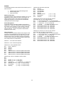
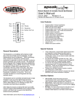
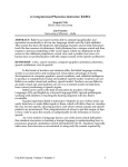
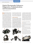
Table C contains a chart of all the consonant and vowel
phonemes of the English language.
Consonants are produced by creating an occlusion or
constriction in the vocal tract, which produces an aperiodic
sound source. If the vocal cords are vibrating at the same
time, as in the case of the voiced fricatives VV, DH, ZZ, and
ZH, there are two sound sources: one which is aperiodic and
one which is periodic.
The result is a system that gives the user the ability to not only
produce an unlimited vocabulary, but also to produce slang,
gibberish, moans, groans, yodels and other weird vocalized
sounds not normally included in a canned TTS system.
Vowels are usually produced with a relatively open vocal tract
and a periodic sound source provided by the vibrating vocal
cords. They are classified according to whether the front or
back of the tongue is high or low (See Figure 4), whether they
are long or short, and whether the lips are rounded or unrounded. In English all rounded vowels are produced in or
near the back of the mouth (UW, UH, OW, OH, AW).
12
Figure 4
How to Use the Allophone Set:
Recall that a phoneme is acoustically different depending upon its
position within a word. Each of these positional variants is an
allophone of the same phoneme. An allophone, therefore, is the
manifestation of a phoneme in true speech signal.
Determining when to use a diphthong and when to use the
independent sound again largely relies on person preference
and local dialect.
Some sounds (P, B, T, D, K, G, CH, and JH) require a brief
duration of silence before them. For these, the silence has
already been added but you may decide you want to add more.
To increase the duration of silence the "SLOW" command can
be used and optionally, a pause can be inserted before it.
The following is a brief tutorial on creating speech using the
SpeakJet allophone set.
Note that these are suggestions, not rules.
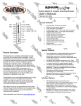
The Phonetic Usage Chart (Refer to Table C) references the
variations of each phoneme of the English language and gives
suggestions for the appropriate times that they are used. For
example, there are 4 B sounds. “BE” and “BO” sound good in
initial position, as in the words "Beep" and "Box" while “EB” and
“OB” sound good in final position, as in "Rib" and "Club". A vowel
modifier is also associated with the “BE”, “BO”, “EB” and “OB”
sounds. The BE is used when followed by a front vowel sound
and the BO is used when followed by a back vowel sound. Note
that either can be used when followed by a central vowel sound.
Also note that a B sound in the middle of a word can be either a
initial position or a final position sound. For example, the word
rabbit; is it RAB-IT or RA-BIT? Local dialect can be the deciding
factor in cases like this.
There are several different types and lengths of pauses that can
be inserted in front of an allophone but be aware that different
pauses will affect the way the MSA calculates the transitions
from the last allophone, through the silence and into the next
allophone which may not produce the desired flow of sounds.
You may want to add a short pause between words and a long
pause between clauses.
Stress can be accomplished in two ways. One is to cause
vowels to play for a longer period of time. For example, in the
word "extent" use the "Fast" command in front of the "EH" in the
first syllable, which is unstressed and a "SLOW" command, or
and additional "EH" in front of the "EH" in the second syllable
which is stressed. A second way is to preceded the allophone
with the "STRESS" and RELAX commands. The STRESS
command duplicates the affect of slightly contracting the
muscles of the mouth and the relax command duplicates the
affects of slightly relaxing the muscles of the mouth. For
example; "STRESS, IH" sounds more like (but not quite) the
"IY" sound. Likewise, "RELAX, IY" sounds more like (but not
quite) an "IH" sound. Note that if you elect to use the
"STRESS" or "RELAX" command in combination with a
phoneme that has been doubled, then two command will be
needed, one in front of each of the phonemes.
Typically the first allophone in a phrase is longer than the rest of
the allophones used with the phrase. Therefore, to create an
initial SS, you can use the SLOW function before the SS
allophone, which will cause the SS sound to play for 1 and 1/2 the
normal speed. If an even longer sound is needed then the SS
allophone can be played twice. (Note that this cannot be done
with all allophones.) Repeating Diphthongs for example will
cause the diphthong slide to play twice which will not result in just
a longer sound.
Diphthongs are perceived as single vowel sounds, but in reality
they are sliding sounds that transition from one vowel sound into
another vowel sound. For example the “A” sound in "Make" isn't a
single vowel sound. It is a diphthong that transitions from the
"EY" sound to the "IY" sound and thusly the name for the
diphthong is "EYIY". This sliding sound is repeated when
diphthongs are repeated. For example: "EYIY, EYIY" does not
have the same affect as "IY, IY". Two "IY" s played back to back
will produce an "IY" sound that lasts twice as long while the
"EYIY, EYIY" will just repeat the slide. Five of the "R" sounds are
diphthongs that begin with a vowel and end with the "R" sound.
For example, the "AWRR" in "alarm" and the "OHRR" in "score".
Remember that you must always think about how a word
sounds, not how it is spelled. For example, The “N” sound in
"Link" is actually the "NGE" sound and the ending sounds in the
words "letter" and “little" use the diphthongs "AXRR" and
"EHEL". Some sounds may not even be represented in words
by any letters, as the "IYUW" in "computer”.
You will want to experiment with all the possible sounds to
discover which version works best in any particular cluster of
allophones.
13
Phonetic Usage Table
• Vowels
Long A - "Gate" & "Ate"
Long E - "See" & "Even"
Long I - "Sky" & "Five"
Long O - "Comb" & "Over"
Long U - "June" & "Food"
Short A - "Hat" & "Fast"
Short E - "Cent" & "Egg"
Short E - "Met" & "Check"
Short E - "Cotton" & "dust"
Short I - "Sit" & "Fix"
Short O - "Hot" & "Clock"
Short U - "Luck" & "Up"
Pair OO - "Book" & "Could"
Pair AW - "Saw" & "Father"
Pair OA - "Coat" & "Hello"
Pair EW - "New" & "Two"
Pair EW - "Few" & "Cute"
Pair IE - "Tie" & "Fight"
Pair OW - “Owl" & "Our"
Pair OW - "Brown"
Pair OY - "Boy" & "Toy"
Y - "Yes" & "Yarn"
• Vowels with R
R - "Ray" & "Brain"
AIR - "Hair" & "Stair"
AR - "Part" & "Farm"
EAR - "Clear" & "Hear"
ER - “Center” & "Fir"
OR - "Corn" & "Four"
• Resonates
EL - "Saddle" & "Angle"
L - "Lake" & "Alarm"
L - "Clock" & "Plus"
W - "Wool" & "Sweat"
• Nasal
M - "Milk" & "Famous"
N - "Nip" & "Danger"
N - "No" & "Snow"
N - "Think" & "Ping"
N - "Hung" & "Song"
\EYIY
\IY
\OHIH
\OW
\UW
\AY
\EY
\EH
\AX
\IH
\OH
\UX
\UH
\AW
\OWWW
\IHWW
\IYUW
\OHIY
\AYWW
\AXUW
\OWIY
\IYEH
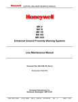
Phonetic Usage Table
• Voiced Fictive
V - "Vest" & "Even"
Z - "Zoo" & "Zap"
ZH - "Azure" & "Treasure"
TH - "There" & "That"
• Voiceless Fricative
H - "Help" & "Hand"
H - "Hoe" & "Hot"
WH - "Who" & "Whale"
F - "Food" & "Effort"
S - "See" & "Vest"
S - "So" & "Sweat"
SH - "Ship" & "Fiction"
TH - "Thin" & "month"
• Voiced Stop
B - "Bear" & "Bird"
B - "Bone" & "Book"
B - "Cab" & "Crib"
B - "Job" & "Sub"
D - "Deep" & "Date"
D - "Do" & "Dust"
D - "Could" & "Bird"
D - "Bud" & "Food"
G - "Get" & "Gate"
G - "Got" & "Glue"
G - "Peg" & "Wig"
G - "Dog" & "Peg"
• Voiceless Stop
T - "Part" & "Little"
T - "Tea" & "Take"
TS - "Parts" & "Costs"
K - "Can't" & "Clown"
K - "Comb" & "Quick"
K - "Speak" & "Task"
K - "Book" & "Took"
P - "People" & "Carpet"
P - "Pod" & "Paw"
• Affricate
JH - "Dodge" & "Jet"
CH - "Church" & "Feature"
Also see IE
Also see OA
Also see OO
Stressed
Normal
Relaxed
Also see AW
Also see Long U
Also see Short O
Also see Long O
eh-oo
ee-oo
Also see Long I
ah-ww
eh-uw
\RR
\EYRR
\AWRR
\IYRR
\AXRR
\OWRR
\EHLL
\LE
\LO
\WW
\MM
\NE
\NO
\NGE
\NGO
Front
Back
Front
Back
Front
Back
\VV
\ZZ
\ZH
\DH
\HE
\HO
\WH
\FF
\SE
\SO
\SH
\TH
Front
Back
\BE
\BO
\EB
\OB
\DE
\DO
\ED
\OD
\GE
\GO
\EG
\OG
Front - Initial
Back - Initial
Front
Back
Front - Initial
Back - Initial
Front
Back
Front - Initial
Back - Initial
Front
Back
\TT
\TU
\TS
\KE
\KO
\EK
\OK
\PE
\PO
\JH
\CH
Table C
(Front) = Usually sounds best when associated with a front or center vowel
(Back) = Usually sounds best when associated with a center or back vowel
(Initial) = Usually sounds best when used in the initial position of word
14
Front
Back
Front - Initial
Front - Initial
Back - Initial
Front
Back
Front
Back
MSA Command Set:
Dec.
SpeakJet Use
---------------------000
Pause 0
001
Pause 1
002
Pause 2
003
Pause 3
004
Pause 4
005
Pause 5
006
Pause 6
007
Play Next Sound Fast
008
Play Next Sound Slow
014
Play Next Sound High Tone
015
Play Next Sound Low Tone
016
Wait
020
Volume, X
021
Speed, X
022
Pitch, X
023
Bend, X
024
PortCtr, X
025
Port, X
026
Repeat, X
028
Call Phrase, X
029
Goto Phrase, X
030
Delay, X
031
Reset Defaults
-------------------------------------------------------032
Reserved
- to 127
-------------------------------------------------------128
127 Sound codes
- to 254
-------------------------------------------------------255
End of Phrase.
Table D
Control Codes Details:
0 - 6 = Pauses.
Pauses of various durations, these will cause the volume to ramp down, wait a specified
amount of time and the ramp back up. 1, 2 & 3, ramp the volume while the format
frequencies are being changed. 4, 5 & 6 wait for silence before changing the format
frequencies.
0 = 0ms
1 = 100ms
2 = 200ms
3 = 700ms
4 = 30ms
5 = 60ms
6 = 90ms
7 = Fast.
Plays the next phoneme at 1/2 the time it normally would play.
8 = Slow
Plays the next phoneme at 1 and 1/2 the time it normally would play.
14 = Stress.
Plays the next phoneme with a small amount of stress in the voice.
15 = Relax
Plays the next phoneme with a small amount of relaxation in the voice.
16 = Wait
This command will stop the voicing and wait for a start command. The Start command
can be issued by either sending the SCP start command or by changing the state of one
of the input lines that has been previously set to do a Start.
20 = Volume, X
This command sets the master volume level. A value will need to be sent after the
volume command that specifies the desired volume. Volume levels can range from 0 to
127. The default is 96.
21 = Speed, X
This command sets the play speed. A value will need to be sent after the speed
command that specifies the desired speed. Speeds can range from 0 to 127. The
default is 114.
22 = Pitch, X
This command sets the Vocalization Pitch in Hertz. A value will need to be sent after
the pitch command that specifies the desired pitch. The vocalization pitch is what makes
a voice sound High pitched or Low pitched. For singing, the pitch has a range of 3 full
octaves (32Hz to 240hz). The Vocalization Pitch works only on sounds that are voiced.
Pitches can range from 0 to 255. The default is 88. Note that anything under 30 starts
to sound like clicks instead of a voice. Also Note that a value of 0 = 0 Hz and thusly, will
not actually vocalize.
23 = Bend, X
This command sets the frequency Bend. A value will need to be sent after the Bend
command that specifies the desired Bend. The frequency Bend adjusts the output
frequencies of the oscillators. This will change the voicing from a deep-hollow sounding
voice to a High-metallic sounding voice. Bends can range from 0 to 15. The default is 5.
24 = PortCtr, X
This command sets the Port Control Value. A value will need to be sent after the
PortCtr command that specifies the desired function of the output lines. The Output line
control bits are binaurally encoded where a 1 indicates that the output function is chip
controlled and a 0 indicates that the output function is user controlled. Bit 0 corresponds
to OUT0, etc… PortCtr values can range from 0 to 7. The default is 7.
25 = Port, X
This command sets the Port Output Value. A value will need to be sent after the Port
command that specifies the desired state of the output lines. When the Output line
control bits are set to 0, the corresponding port bit is represented on the output line. Bit
0 corresponds to OUT0, etc… Port values can range from 0 to 7. The default is 0.
26 = Repeat, X
This command sets a number of times to Repeat the next code. A value will need to be
sent after the Repeat command that specifies the number of times to repeat the next
command.
The Repeat range is from 0 to 255.
28 = Call Phrase, X
This command specifies which EEPROM phrase to play then to return from.
This can be nested 3 deep maximum.
29 = Goto Phrase, X
This command specifies which EEPROM phrase to play.
30 = Delay, X
This command specifies the number of 10ms intervals to delay before continuing
on to the next code. The Delay range is from 0 to 255.
31 = Reset
This command resets the Volume, Speed, Pitch and Bend to the default values.
15
MSA Sound Allophone Component List:
Code Phoneme
------ -----------128
IY
129
IH
130
EY
131
EH
132
AY
133
AX
134
UX
135
OH
136
AW
137
OW
138
UH
139
UW
140
MM
141
NE
142
NO
143
NGE
144
NGO
145
LE
146
LO
147
WW
148
RR
149
IYRR
150
EYRR
151
AXRR
152
AWRR
153
OWRR
154
EYIY
155
OHIY
156
OWIY
157
OHIH
158
IYEH
159
EHLL
160
IYUW
161
AXUW
162
IHWW
163
AYWW
164
OWWW
165
JH
166
VV
167
ZZ
168
ZH
169
DH
170
BE
171
BO
172
EB
173
OB
174
DE
175
DO
176
ED
177
OD
178
GE
179
GO
180
EG
181
OG
182
CH
183
HE
184
HO
185
WH
186
FF
187
SE
188
SO
189
SH
190
TH
191
TT
192
TU
193
TS
194
KE
195
KO
196
EK
197
OK
198
PE
199
PO
Samle Words
----------------------See, Even, Feed
Sit, Fix, Pin
Hair, Gate, Beige
Met, Check, Red
Hat, Fast, Fan
Cotten
Luck, Up, Uncle
Hot, Clock, Fox
Father, Fall
Comb, Over, Hold
Book, Could, Should
Food, June
Milk, Famous,
Nip, Danger, Thin
No, Snow, On
Think, Ping
Hung, Song
Lake, Alarm, Lapel
Clock, Plus, Hello
Wool, Sweat
Ray, Brain, Over
Clear, Hear, Year
Hair, Stair, Repair
Fir, Bird, Burn
Part, Farm, Yarn
Corn, Four, Your
Gate, Ate, Ray
Mice, Fight, White
Boy, Toy, Voice
Sky, Five, I
Yes, Yarn, Million
Saddle, Angle, Spell
Cute, Few,
Brown, Clown, Thousand
Two, New, Zoo
Our, Ouch, Owl
Go, Hello, Snow
Dodge, Jet, Savage
Vest, Even,
Zoo, Zap
Azure, Treasure
There, That, This
Bear, Bird, Beed
Bone, Book Brown
Cab, Crib, Web
Bob, Sub, Tub
Deep, Date, Divide
Do, Dust, Dog
Could, Bird
Bud, Food
Get, Gate, Guest,
Got, Glue, Goo
Peg, Wig
Dog, Peg
Church, Feature, March
Help, Hand, Hair
Hoe, Hot, Hug
Who, Whale, White
Food, Effort, Off
See, Vest, Plus
So, Sweat
Ship, Fiction, Leash
Thin, month
Part, Little, Sit
To, Talk, Ten
Parts, Costs, Robots
Can't, Clown, Key
Comb, Quick, Fox
Speak, Task
Book, Took, October
People, Computer
Paw, Copy
MSA Sound Effects Component List:
Msec.
-------70
70
70
70
70
70
70
70
70
70
70
70
70
70
70
70
70
70
70
70
70
200
200
190
200
185
165
200
225
185
170
140
180
170
170
200
131
70
70
70
70
70
45
45
10
10
45
45
10
10
55
55
55
55
70
70
70
70
70
40
40
50
40
50
70
170
55
55
55
45
99
99
Phoneme Type
--------------------Voiced Long Vowel
Voiced Short Vowel
Voiced Long Vowel
Voiced Short Vowel
Voiced Short Vowel
Voiced Short Vowel
Voiced Short Vowel
Voiced Short Vowel
Voiced Short Vowel
Voiced Long Vowel
Voiced Short Vowel
Voiced Long Vowel
Voiced Nasal
Voiced Nasal
Voiced Nasal
Voiced Nasal
Voiced Nasal
Voiced Resonate
Voiced Resonate
Voiced Resonate
Voiced Resonate
Voiced R Color Vowel
Voiced R Color Vowel
Voiced R Color Vowel
Voiced R Color Vowel
Voiced R Color Vowel
Voiced Diphthong
Voiced Diphthong
Voiced Diphthong
Voiced Diphthong
Voiced Diphthong
Voiced Diphthong
Voiced Diphthong
Voiced Diphthong
Voiced Diphthong
Voiced Diphthong
Voiced Diphthong
Voiced Affricate
Voiced Fictive
Voiced Fictive
Voiced Fictive
Voiced Fictive
Voiced Stop
Voiced Stop
Voiced Stop
Voiced Stop
Voiced Stop
Voiced Stop
Voiced Stop
Voiced Stop
Voiced Stop
Voiced Stop
Voiced Stop
Voiced Stop
Voiceless Affricate
Voiceless Fricative
Voiceless Fricative
Voiceless Fricative
Voiceless Fricative
Voiceless Fricative
Voiceless Fricative
Voiceless Fricative
Voiceless Fricative
Voiceless Stop
Voiceless Stop
Voiceless Stop
Voiceless Stop
Voiceless Stop
Voiceless Stop
Voiceless Stop
Voiceless Stop
Voiceless Stop
Code Phoneme
------ -----------200
R0
201
R1
202
R2
203
R3
204
R4
205
R5
206
R6
207
R7
208
R8
209
R9
210
A0
211
A1
212
A2
213
A3
214
A4
215
A5
216
A6
217
A7
218
A8
219
A9
220
B0
221
B1
222
B2
223
B3
224
B4
225
B5
226
B6
227
B7
228
B8
229
B9
230
C0
231
C1
232
C2
233
C3
234
C4
235
C5
236
C6
237
C7
238
C8
239
C9
240
D0
241
D1
242
D2
243
D3
244
D4
245
D5
246
D6
247
D7
248
D8
249
D9
250
D10
251
D11
252
M0
253
M1
254
M2
Table E
16
Sample Words
-------------------
0
1
2
3
4
5
6
7
8
9
*
#
Sonar Ping
Pistol Shot
WOW
MS
---80
80
80
80
80
80
80
80
80
80
300
101
102
540
530
500
135
600
300
250
200
270
280
260
300
100
104
100
270
262
160
300
182
120
175
350
160
260
95
75
95
95
95
95
95
95
95
95
95
95
95
95
125
250
530
Phoneme Type
--------------------Robot
Robot
Robot
Robot
Robot
Robot
Robot
Robot
Robot
Robot
Alarm
Alarm
Alarm
Alarm
Alarm
Alarm
Alarm
Alarm
Alarm
Alarm
Beeps
Beeps
Beeps
Beeps
Beeps
Beeps
Beeps
Beeps
Beeps
Beeps
Biological
Biological
Biological
Biological
Biological
Biological
Biological
Biological
Biological
Biological
DTMF
DTMF
DTMF
DTMF
DTMF
DTMF
DTMF
DTMF
DTMF
DTMF
DTMF
DTMF
Miscellaneous
Miscellaneous
Miscellaneous
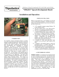
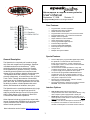
18 Pin Plastic DIP Package Mechanical Specifications
Glossary of Terms
al·lo·phone n.
A predictable phonetic variant of a phoneme. For example, the aspirated T of Top, the unaspirated T of sTop, and the TT (pronounced
as a flap) of baTTer are allophones of the English phoneme /T/.
pho·neme n.
The smallest phonetic unit in a language that is capable of conveying a distinction in meaning, as the M of Mat and the B of Bat in the
English language.
SCP
Serial Control Protocol
A communications and control standard developed by Savage Innovations and licensed by Magnevation for communications of data
to internal registers.
syl·la·ble n.
A unit of spoken language consisting of a single uninterrupted sound formed by a vowel, diphthong, or syllabic consonant alone, or by
any of these sounds preceded, followed, or surrounded by one or more consonants.
syn·the·sis n.
The combining of separate elements or substances to form a coherent whole.
17