1
Vibrating Wire Soil Extensometer
Users Manual
Man 065
3.1.1
04/08/2016
P. Day
Andy Small
Chris Rasmussen
Manual No.
Revision
Date
Originator
Checked
Authorised for
Issue
User Manual
1
Contents
Section 1 :
Introduction ................................................................................................................................ 3
Section 2 :
Preparation of Equipment Prior To Installation ............................................................ 4
Section 3 :
Cable Connections to the Extensometer ("Splicing") ................................................. 5
3.01
3.02
3.03
3.04
Section 4 :
4.01
4.02
4.03
4.04
4.05
4.06
Section 5 :
5.01
5.02
5.03
Preparation of the Cables ............................................................................................................ 5
Conductor Connections ................................................................................................................ 5
Fitting Mould .................................................................................................................................. 5
Filling with Resin ........................................................................................................................... 5
Installation................................................................................................................................... 6
Points to consider prior to installation ...................................................................................... 6
Installation Procedure .................................................................................................................. 6
Extensometer Adjustment ........................................................................................................... 7
Extending the Extensometer ...................................................................................................... 7
Compressing the Extensometer ................................................................................................. 8
Post Adjustment Backfilling and Precautions to be observed .............................................. 8
Taking Readings and Monitoring ......................................................................................... 9
Taking Readings ............................................................................................................................ 9
Monitoring ....................................................................................................................................... 9
Frequency of readings .................................................................................................................. 9
Section 6 :
Data Interpretation ................................................................................................................ 11
Section 7 :
Troubleshooting Guide .......................................................................................................... 13
Appendix A.
Trouble Shooting Flowchart ................................................................................................ 15
Appendix B.
Sample Calibration Certificate ............................................................................................ 16
Appendix C.
Installation Overview Diagram .......................................................................................... 17
User Manual
2
Section 1 : Introduction
The Vibrating Wire Soil Extensometer measures horizontal extension or compression of the
material within which it is installed. Data from the Extensometer can be used to calculate
strain values.
Extensometers can be installed in the following two fashions:
(1)
Singly. In this case the relative movement between two anchor beams is measured.
(2)
Multiple Extensometer bays can be connected together "in series" to create a "Chain
Extensometer".
The Extensometer comprises a Vibrating Wire Displacement Transducer in a sealed housing.
The transducer is connected to a piston with a stroke of 300mm 0.5% of range. The piston is
threaded to receive steel extension rods which are connected together to create the required
gauge length. Telescoping PVC tubes fit over the extension rods to eliminate friction between
the rods and the material within which they are installed.
If it is known prior to installation that an Extensometer will be subject to predominantly
extensive or compressive movement, then it can be installed either completely compressed or
completely extended to increase the measurable range of compressive or extensive movement.
It is not known whether future movements will be extensive or compressive; the Extensometer
piston can initially be set at the mid point of its range.
User Manual
3
Section 2 : Preparation of Equipment Prior To Installation
As soon as equipment arrives on site, even if installation is not to follow immediately, there
should be a check that all necessary parts are present and in good working order.
Prior to installation, the following tasks are necessary:
The transducer(s) should be subjected to simple functioning tests.
These can take the form of listening to the audio signal while watching the measured period
from each transducer through the portable vibrating wire readout unit and verifying that the
transducers measure their full range when extended fully. A consistent, sharp audio signal
with period measurement that does not change by more than ± 2 verifies the vibrating wire is
operating correctly and the range check verifies that the gauge factor supplied is correct.
The length of cable required to connect the transducer to the desired final readout location
should be cut and colour coded using adhesive tape in accordance with the site convention.
This cable can either be spliced to the transducer prior to installation or the "splice" can be
carried out on site. This "splice" method is described in Section 3.
With an instrument of this nature, it is always advisable to carry out a practice installation
preferably under cover. This procedure verifies that all component parts are present and fit
together correctly. A practice installation is also useful training for technicians, possibly
inexperienced in this type of installation.
User Manual
4
Section 3 : Cable Connections to the Extensometer ("Splicing")
The extensometer is supplied with 1m of cable attached at the factory. This short length of
cable is joined to the connecting cable using the cable jointing kit provided. The conductors
should be matched colour for colour.
3.01 Preparation of the Cables
Thoroughly scrape all wax and dirt from each cable sheath over a distance of approximately
150mm from each end to be joined. Prepare the cable ends exactly as shown in Drawing No.
A4/P5045. Stagger the individual conductor connections.
3.02 Conductor Connections
Use the crimped connectors to join the conductors and use the electrical insulation tape to
wrap the connectors. Stretch the tape to half its original width and apply one layer half lapped
over connector area only (Drawing No. A4/P5046). Where armoured cable is used, 3 out of
every 7 armour strands should be cut off and the remaining 4 wrapped around the crimped
connections to ensure continuity of the earth connections and provide protection.
3.03 Fitting Mould
Trim the ends of the mould with a sharp knife to suit the diameter of the cable. Hold the
mould halves in place centred over the splice. Snap both halves together and fit the pouring
spouts in the holes. Ensure that both seams are completely snapped together. Tape the ends
of the mould body to form a seal.
3.04 Filling with Resin
Release the separating seal of the resin bag by pulling it apart and mix the resin thoroughly.
Maintaining the mould in a level position, spouts uppermost, pour the resin through one spout
until both spouts are completely filled. When the resin has solidified and cooled remove the
spouts by carefully sawing them off at their base.
NOTE In cold weather (below 15 degrees C) the resin becomes very viscous. It is
therefore advisable to keep the resin in a warm place (say inside clothing)
prior to mixing. Mix the compound until its temperature starts to rise, this
decreases the viscosity.
User Manual
5
Section 4 : Installation
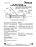
The installation layout for the Extensometer is shown on Drg.No. A3/915-018(B). The gauge
length can be adjusted to suit a particular client's needs. Drg.No. A3/859-002 shows the
details of how the transducer and adjustment unit are connected to an anchor beam.
Tools you will need during the installation procedure include:
A hacksaw.
A file.
An M12 die and die holder.
A suitable lubricant (say grease).
An adjustable spanner.
4.01 Points to consider prior to installation
A clear sketch of the installation should be made prior to installation identifying the location of
each transducer so that any subsequently measured movements are clearly
understood.
If individual bays of the Extensometers are of a length which will require the cutting and rethreading of extension rods, this is best done in a workshop prior to commencing
installation on site. Knowledge of intended anchor beam locations together with transducer
and adjustment unit lengths can be used to calculate the final required lengths of all extension
rods.
It is usual to fix one of the Extensometer anchor beams to either a location considered fixed
(perhaps a concrete wall) or a point which can be surveyed regularly such as a survey
monument.
Where Extensometer rods and/or electrical cables are to cross an interface between materials
of different physical properties, consideration should be given to potential shear forces caused
by differential settlements of the two materials. PVC tubes and cables should be embedded
locally in a weaker fill to protect against possible damage.
The backfill material for the PVC protective tubes should be of SIMILAR or WEAKER strength
than the parent material. The backfill material used in the vicinity of the anchor beams should
be of SIMILAR or GREATER strength than the surrounding ground.
4.02 Installation Procedure
The base of the trench for installation should be made perfectly flat. At least 150mm of sand
or stone free clay or silt should be placed under the desired locations of Extensometers, cables
and PVC tubes. The width of this main trench will be 600mm to 1000mm.
At anchor beam locations, the trench should be extended 500mm into each side and
approximately 50mm downwards.
The beams are placed at the desired locations and material is compacted over the end 500mm
of each beam. Remember to line up the holes in the beams for adjustment unit and transducer
along the line of the trench. This will ensure that the Extensometer runs straight and does not
"Zig Zag" along the length of the trench.
User Manual
6
Thread the boss of the first Extensometer through the larger hole in the first anchor beam.
Align the boltholes in the flange and anchor beam and securely bolt together.
At the next beam in line, thread the adjustment unit studding through the smaller hole. Place
the adjustment unit boss over the studding and then screw the fixing bolts over the studding
to leave the adjustment studding at approximately the correct extension.
Using the female/female connector supplied, screw a connecting rod to the end of the
Extensometer piston and tighten. Take precautions not to turn the transducer piston as this
can cause damage.
Locate two degreased O-rings over the Extensometer boss and carefully slide one of the larger
diameter PVC protection tubes over these rings.
If it is thought that silt or other material may ingress through the boss/tube or tube/tube
joints, these joints can be wrapped with a sealing tape such as "denso".
Connect extension rods and PVC tubes in that order until the required gauge length is
obtained.
Approximately a 500mm overlap together with a double O-ring seal should be used at each
tube/tube joint. At each overlap the outside of the smaller tube and the inside at the larger
tube should be cleaned. O rings should also be cleaned.
The last extension rod of a bay couples to the adjustment rod of the adjustment unit. It is at
this stage that the extension rod will have to be cut and re-threaded if this was not done in the
workshop prior to installation on site. Prior to connection of the last extension rod, it should be
ensured that the chain of protective tubes runs straight and level and are supported by a small
mound of sand, silt or stone free clay.
NOTE The adjustment unit boss accepts the larger diameter PVC tube, as does the
Extensometer, so the tubes should be configured to accommodate this!
Before locating the final PVC tube over the adjustment unit boss, it is necessary to first adjust
the Extensometer.
4.03 Extensometer Adjustment
NOTE It is vitally important prior to adjustment that it be understood that an
extension of the piston (implying an increase in separation of anchor beams)
will cause a positive increase in reading in millimetres of extension on the
vibrating wire portable logger so long as the negative Gauge Constant ("K"
values) are used.
Connect the cable ends to the portable logger during adjustment in order to observe the
changes in extension which take place.
4.04 Extending the Extensometer
To extend the Extensometer, completely slacken off the nut on the adjustment studding closest
to the transducer. The nut outside the anchor beam can now be turned to draw the
adjustment studding out. While doing this, care should be taken to ensure that the studding
does not turn as this may affect the studding/extension rod screw thread connection.
User Manual
7
After drawing out the Extensometer to the required adjustment, the nut inside the anchor
beam should now be tightened to lock the adjustment studding in place.
4.05 Compressing the Extensometer
To compress the Extensometer, completely slacken the nut on the adjustment studding outside
the anchor beam. The nut inside the anchor beam can now be tightened with a spanner, thus
forcing back the extension rods. Again, care should be taken to ensure the studding does not
turn during this process.
After compressing the Extensometer as required, the nut outside the anchor beam should be
tightened to lock the adjustment rod in place.
After adjustment, the larger diameter PVC tube should be located over the adjustment unit
boss with a double O-ring seal.
4.06 Post Adjustment Backfilling and Precautions to be observed
The backfilling of the trench should initially be carried out by hand so as not to disturb the
Extensometer.
At least 150mm of stone free cover to the Extensometer is necessary.
Subsequent backfilling should be carried out in layers, layer thickness depending upon type of
material used and standard of compaction required.
Particular attention should be given to electrical cables crossing anchor beams. Build up a
gradual ramp of well compacted selected material to at least 150mm thickness above the
anchor beam before laying cables.
Where extensive strains are anticipated the cables should be "snaked" allowing sufficient slack
to accommodate the strain.
Backfill around the anchor beams should be extremely well compacted, ensuring that
movements of anchor beams represent ground movements.
Carefully check and record the position of trenches on the site plan, and take precautions to
prevent subsequent damage by excavation or passing machines.
Take frequent readings during backfilling operations as a check against accidental damage to
the cables.
User Manual
8
Section 5 : Taking Readings and Monitoring
5.01 Taking Readings
Vibrating Wire Soil Extensometer can be read with Itmsoil Data Logger or any other readout
capable of reading a vibrating wire transducer. The wire of the sensor is excited to oscillate at
its resonant frequency which is then accurately measured by counting the number of oscillation
cycles. The reading can be obtained from the logger as raw data in terms of normal reading
(Period x 107) or linear reading (f²/1000). If a logger channel is dedicated for one particular
instrument and a table set up (refer to logger user's manual) for that channel, the readings
can be obtained and logged/stored in the logger memory directly in millimetres or inches of
displacement with reference to the initial setting up reading. It is extremely important to
establish a reference reading (or "base" reading) at the time of installation and initial setting
up. Store this reading for zero displacement with gauge factor for a particular Extensometer.
The logger will display +ive displacement for extension strain and -ive displacement for
compressive strain once a negative factor given in the calibration certificate is stored in its
table at a dedicated channel. (This is explained further in the "Data Interpretation" section).
5.02 Monitoring
Throughout the construction of and operating life of the structure within which it is installed,
the vibrating wire Soil Extensometer may be monitored in the following fashions:During construction it may be the case that only the naked ends of the conductors in the cable
are available for reading the instrument. The instrument can be read at this stage using a lead
from the portable logger with two crocodile clips which connect to the conductors.
The cables may be connected to a terminal box from which many transducers can be read
using the portable logger.
The cables may be connected to a Itmsoil data logger either separately or more conveniently
for longer cable runs, via multi-core cables.
The Soil Instruments data logger can be programmed to take a series of pre-programmed
readings over time of any V.W. instruments connected to it. The data from these readings can
be downloaded to computer and presented using the Itmsoil Data Management Software
Package I-Site.
5.03 Frequency of readings
The frequency with which readings of the vibrating wire Soil Extensometer are taken will
depend on the stage of construction and the behaviour of the structure after completion. The
following points are relevant:
Immediately after installation it is a good idea to take readings as frequently as twice daily.
This is to ensure that construction activity during backfilling has not damaged the
Extensometer or its related electrical cables. This should be carried on until the Extensometer
is beneath a depth of fill such that it cannot be damaged by further construction activity.
During the general construction phase of the project, a normal reading frequency for the
Extensometer would be once every two weeks.
After completion of the structure, the frequency with which readings are taken may be set at
even less than once every two weeks. If an increased rate of change in the readings is
User Manual
9
observed, then it may be necessary to increase the frequency with which readings are taken in
order to properly record any movement taking place.
User Manual
10
Section 6 : Data Interpretation
Calculation of Engineering units from frequency-based units.
The mathematical relationship between the frequency of vibration of a tensioned wire and the
force applying the tension is an approximate straight line relationship between the square of
the measured frequency and the applied force.
Engineering units of measurement maybe derived from the frequency-based units measured
by vibrating wire readouts, in 3 traditional ways:From ‘Period’ units (t x 107) and from ‘Linear’ (f^2/1000) units using two methods: a simple
Linear equation or a Polynomial equation.
Calculation using ‘Period’ units.
The following formula is used for readings in ‘Period’ units.
E = K (10^7/P0^2 – 10^7/P1^2)
Where;
E is the Pressure in resultant Engineering units,
K is the Period Gauge Factor for units of calibration (from the calibration sheet)
P0 is the installation Period ‘base’ or ‘zero’ reading
P1 is the current Period reading.
This method of calculation is used by the Itmsoil Vibrating Wire loggers’ (models RO-1-VW-1 or
2 and with serial numbers starting VL or TVL) internal processors’, for calculating and
displaying directly on the loggers’ LCD screen, the required Engineering based units.The
loggers’ require ‘Period’ base or zero reading units for entering into their channel tables, to
calculate and display correctly the required engineering units.
If an Engineering-based unit is required other than the units of calibration, then the correct K
factor will have to be calculated using the standard relationship between Engineering units.
For example, if the units of engineering required were in inches and the calibration units were
mm, we can find out that 1mm is equal to 0.03937 inches, so we would derive the K factor for
inches by multiplying the K factor for mm by 0.03937.
Calculation using Linear units.
The following formula is used for readings in ‘Linear’ units.
E = G (R0 – R1)
Where;
E is the resultant Engineering unit,
G the linear Gauge factor for the units of calibration (from the calibration sheet)
R0 is the installation Linear ‘base’ or ‘zero’ reading
R1 is the current Linear reading.
Again the Linear gauge factor for units other than the units of calibration would need to be
User Manual
11
calculated using the same principles as stated in the last paragraph of the ‘Period unit’ section.
Linear unit calculation using a Polynomial equation.
Linear units maybe applied to the following polynomial equation, for calculation of
engineering units to a higher order of accuracy.
E = AR1^2 + BR1 + C
Where;
E is the resultant Engineering unit
A, B and C the Polynomial Gauge factors A, B and C, from the instrument’s calibration sheet
and R1 is the current linear reading.
The value C is an offset value and relates to the zero value experienced by the transducer at
the time of calibration. This value should be re-calculated at the installation time as follows:
C = - (AR0^2 + BR0)
Where;
A and B are as above
R0 is the installation Linear ‘base’ or ‘zero’ reading.
Please note that the sign of the re-calculated value of C, should be the same as the original
value of C, so if the original is negative then the recalculated value should also be negative.
Conversion to engineering units other than the units of calibration, would best be done after
conversion, using a factor calculated using the same principles as stated in the last paragraph
of the ‘Period unit’ section.
User Manual
12
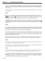
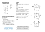
Section 7 : Troubleshooting Guide
If a failure of any vibrating wire transducer or the electrical cable is suspected, the following
steps can be followed. The transducers themselves are sealed and cannot be opened for
inspection. The "Troubleshooting Flowchart" should also be followed if any instrument failures
are suspected.
The steps below and the Troubleshooting Flowchart are applicable generally to any vibrating
wire instrument.
STEP 1
Before any of the following steps are followed, the readout unit should be used to verify the
stability of the reading and the audio signal from the portable logger should be heard. An
unstable (wildly fluctuating) reading from a transducer or an unsteady audio signal are both
indications of possible problems with instruments or their related electrical cables.
* Important: If a portable data logger is giving faulty readings or audio signals from all
transducers, a faulty readout unit must be suspected. Another readout unit should be used to
check the readings from the transducers and Itmsoil Ltd should be consulted about the faulty
readout unit.
STEP 2
The resistance across the two conductors of the electrical cable should be checked. This can be
done using a multimeter device across the two exposed conductors if the cable has not been
connected to a terminal cabinet, or can be done just as easily across the two conductors if the
instrument has been connected to such a terminal (or datalogger).
The resistance across the two conductors should be approximately of the order of 120 to
180. The majority of this resistance will come from the transducer (say approximately 130)
and the remainder from the electrical cable connected to the transducer (for 22 gauge copper,
resistance is approximately 1/15m.
Before proceeding to Steps 2 and 3, the continuity should be checked between conductors and
earthing screen of the electrical cable. If continuity exists, a damaged cable is confirmed.
STEP 3
If the resistance across the two conductors is much higher than the values quoted in "STEP 1"
(or is infinite), a severed cable must be suspected.
If the location on site of cable damage is found, the cable can be repaired using the method
outlined in Section 3, "Cable Connections to the Extensometer".
STEP 4
If the resistance across the two conductors is much lower than the values quoted in "STEP 1"
(say 80O or less) it is likely that cable damage has occurred causing a short in the circuit.
It is possible to calculate approximately how far from the cable end (or readout location) the
suspected circuit break is. If the resistance of a known length of conducting cable is measured,
a resistance/unit length can be found. This figure can be used to calculate the length of
conductor cable in between readout location and the "short".
User Manual
13
(It must be remembered that this method is only applicable if the "short" occurs between the
two conductors of the electrical cable. Since cables are generally buried and hidden it is
usually impossible to confirm the short is of this nature. It should therefore be remembered
this method can be used as a rough guide only).
STEP 5
If the resistance is within the values quoted in "STEP 1" (i.e. 120 to 180), AND no continuity
exists between conductor and earth screen and on checking the reading from the transducer, it
proves to be still unstable or wildly fluctuating, it must be assumed that the integrity of the
circuit is good. A faulty transducer must be suspected and Itmsoil Ltd should be consulted.
If the location on site of cable damage is found, the cable can be spliced in accordance with
recommended procedure.
Bell Lane, Uckfield, East Sussex
t: +44 (0) 1825 765044
e: [email protected]
TN22 1QL United Kingdom
f: +44 (0) 1825 744398
w: www.itmsoil.com
Soil Instruments Ltd. Registered in England. Number: 07960087. Registered Office: 5th Floor, 24 Old Bond Street, London, W1S 4AW
User Manual
14
Appendix A.
Trouble Shooting Flowchart
User Manual
15
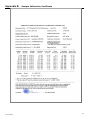
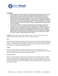
Appendix B.
User Manual
Sample Calibration Certificate
16
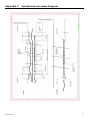
Appendix C. Installation Overview Diagram
User Manual
17