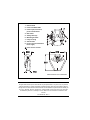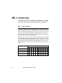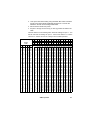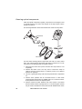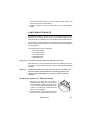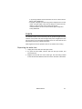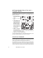
1
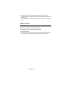
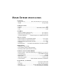
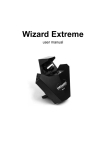
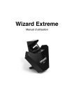
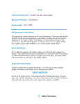
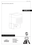
Wizard Extreme
user manual
1. Data sockets
2. Power and Data LEDs
6 7
3. Power input, main fuse,
power on/off switch
4. DIP switch
5. Safety cable eye
6. Mounting bracket
7. Lamp housing
8. Swivel locks
9. Focus rod (see illustration
below right)
1
2
3
4
5
8
Cover access screws
516
208
9
552
110
Measurements are in millimeters
© 2004-2007 Martin Professional A/S, Denmark.
All rights reserved. No part of this manual may be reproduced, in any form or by any means,
without permission in writing from Martin Professional A/S, Denmark. Information subject to
change without notice. Martin Professional A/S and all affiliated companies disclaim liability for
any injury, damage, direct or indirect loss, consequential or economic loss or any other loss
occasioned by the use of, inability to use or reliance on the information contained in this
manual.
P/N 35000155, Rev. F
Introduction . . . . . . . . . . . . . . . . . . . . . . . . . . . . . . . . . . . . . . . . . . . 5
Safety information . . . . . . . . . . . . . . . . . . . . . . . . . . . . . . . . . . . . . 5
Unpacking . . . . . . . . . . . . . . . . . . . . . . . . . . . . . . . . . . . . . . . . . . . 7
AC power . . . . . . . . . . . . . . . . . . . . . . . . . . . . . . . . . . . . . . . . . . . . . 8
Installing a plug on the mains lead . . . . . . . . . . . . . . . . . . . . . . . . 8
Adjusting voltage settings . . . . . . . . . . . . . . . . . . . . . . . . . . . . . . . 8
Installation . . . . . . . . . . . . . . . . . . . . . . . . . . . . . . . . . . . . . . . . . . . 11
Wall mounting . . . . . . . . . . . . . . . . . . . . . . . . . . . . . . . . . . . . . . . 11
Overhead mounting . . . . . . . . . . . . . . . . . . . . . . . . . . . . . . . . . . . 12
Operation from the floor . . . . . . . . . . . . . . . . . . . . . . . . . . . . . . . 12
Multi-coupler bracket . . . . . . . . . . . . . . . . . . . . . . . . . . . . . . . . . . 14
Data connection . . . . . . . . . . . . . . . . . . . . . . . . . . . . . . . . . . . . . . 15
Recommended cable . . . . . . . . . . . . . . . . . . . . . . . . . . . . . . . . . 15
Connections . . . . . . . . . . . . . . . . . . . . . . . . . . . . . . . . . . . . . . . . 15
Stand-alone operation . . . . . . . . . . . . . . . . . . . . . . . . . . . . . . . . 17
Single-unit operation . . . . . . . . . . . . . . . . . . . . . . . . . . . . . . . . . . 17
Master / slave operation . . . . . . . . . . . . . . . . . . . . . . . . . . . . . . . 17
Stand-alone settings . . . . . . . . . . . . . . . . . . . . . . . . . . . . . . . . . . 19
MC-1 operation . . . . . . . . . . . . . . . . . . . . . . . . . . . . . . . . . . . . . . . 20
MC-1 settings . . . . . . . . . . . . . . . . . . . . . . . . . . . . . . . . . . . . . . . 20
DMX operation . . . . . . . . . . . . . . . . . . . . . . . . . . . . . . . . . . . . . . . 21
DMX modes . . . . . . . . . . . . . . . . . . . . . . . . . . . . . . . . . . . . . . . . 21
Setting the DMX mode . . . . . . . . . . . . . . . . . . . . . . . . . . . . . . . . 24
DMX control address . . . . . . . . . . . . . . . . . . . . . . . . . . . . . . . . . . 24
Basic service . . . . . . . . . . . . . . . . . . . . . . . . . . . . . . . . . . . . . . . . . 26
Cleaning . . . . . . . . . . . . . . . . . . . . . . . . . . . . . . . . . . . . . . . . . . . 26
Lamp maintenance . . . . . . . . . . . . . . . . . . . . . . . . . . . . . . . . . . . 29
Fuses . . . . . . . . . . . . . . . . . . . . . . . . . . . . . . . . . . . . . . . . . . . . . 31
Setting Wizard emulation and 1-channel modes . . . . . . . . . . . . . 32
Updating firmware . . . . . . . . . . . . . . . . . . . . . . . . . . . . . . . . . . . . 32
Troubleshooting . . . . . . . . . . . . . . . . . . . . . . . . . . . . . . . . . . . . . . 34
DMX protocol: 11-channel mode . . . . . . . . . . . . . . . . . . . . . . . 35
DMX protocol: Wizard emulation 8-channel mode . . . . . . . 38
DMX protocol: 1-channel mode . . . . . . . . . . . . . . . . . . . . . . . . 40
Wizard Extreme specifications . . . . . . . . . . . . . . . . . . . . . . . . 41
Disposing of this product
Martin® products are supplied in compliance with Directive
2002/96/EC of the European Parliament and of the Council
of the European Union on WEEE (Waste Electrical and
Electronic Equipment), as amended by Directive
2003/108/EC, where applicable.
Help preserve the environment! Ensure that this product is
recycled at the end of its life. Your supplier can give details
of local arrangements for the disposal of Martin® products.
I NTRODUCTION
Thank you for selecting the Martin Wizard Extreme. The Wizard Extreme
is an automated lighting fixture that features:
• 12 factory-designed macros that allow light shows to be created quickly
with minimal programming
• Strobe effects
• Two independent color/gobo wheels
• Seven solid colors, eight-split colors, and two white positions
• 13 gobos plus open position
• A rotating mirror dish
• A rotating mirror drum with variable swivel angle
• Adjustable focus with rapid adjustment mechanism
• Mechanical shutter
• Multiple control options that enable a broad range of effects
The combination of mirror dish and mirror drum delivers over 80 individual
light beams. A new glass reflector design offers enhanced light output.
SAFETY INFORMATION
Warning!
This product is not for household use. It presents risks of
lethal or severe injury due to fire and heat, electric shock, and
falls.
Read this manual before powering or installing the fixture, follow the
safety precautions listed below and observe all warnings in this manual
and printed on the fixture. If you have questions about how to operate the
fixture safely, please contact a Martin distributor for assistance. Refer any
service operation not described in this manual to a qualified technician.
Do not modify the fixture or install other than genuine Martin accessories
and upgrade kits.
Avoi di ng electric shocks
• Disconnect the fixture from AC power before removing or installing the
lamp, fuses, or any part, and when not in use.
• Always ground (earth) the fixture electrically.
Introduction
5
• Use only a source of AC power that complies with local building and
electrical codes and has both overload and ground-fault protection.
• Do not expose the fixture to rain or moisture.
• Refer all service to a qualified technician.
• Never operate the fixture with missing or damaged lenses and/or
covers.
Prot ecting yourself and others from burns and fire
• Never attempt to bypass the thermostatic switch or fuses. Always
replace defective fuses with ones of the specified type and rating.
• Ensure that the air flow through fans and vents is free and unobstructed.
• Keep all combustible materials (for example fabric, wood, paper) at
least 0.3 meters (12 inches) away from the fixture. Keep flammable
materials well away from the fixture.
• Do not illuminate surfaces within 0.1 meters (4 inches) of the fixture.
• Provide a minimum clearance of 0.1 meters (4 inches) around fans and
air vents.
• Replace the lamp if it becomes defective or worn out, or before usage
exceeds the maximum service life. When replacing the lamp, allow the
fixture to cool for at least 5 minutes before opening the fixture or
removing the lamp. Protect your hands and eyes with gloves and safety
glasses. It can take up to 15 minutes for the fixture to cool completely.
• Never place filters or other materials over the lens or mirror drum.
• The exterior of the fixture can reach temperatures up to 60° C (140° F)
and the screws on the lamp plate can reach up to 90° C (194° F). Allow
the fixture to cool for at least 5 minutes before handling.
• Do not operate the fixture if the ambient temperature (Ta) exceeds 40° C
(104° F).
• Do not stare directly into the light.
• Never operate the fixture without all lenses and covers installed: an
unshielded lamp can explode without warning and emits dangerous UV
radiation that can cause burns and eye damage.
• Covers, shields, lenses or ultraviolet screens must be changed if they
have become visibly damaged.
• The lamp must be changed if it has become damaged or thermally
deformed.
Preventing injuri es due to fall s
• When suspending the fixture above ground level, verify that the
structure can hold at least 10 times the weight of all installed devices.
6
Wizard Extreme user manual
• Verify that all external covers and rigging hardware are securely
fastened and use an approved means of secondary attachment such as
a safety cable.
• Block access below the work area whenever installing or removing the
fixture.
UNPACKING
The packing material is carefully designed to protect the fixture during
shipment – always use it to transport the fixture.
The Wizard Extreme is supplied with the following:
• 3-wire power cable.
• This user manual. The latest version of this manual is also available in
the support area of the Martin website at http://www.martin.com
Introduction
7
AC POWER
The Wizard Extreme’s operating voltage is printed on the serial number
label that can be found on the back of the Wizard Extreme. Verify that the
operating voltage closely matches the AC supply voltage before applying
power. Contact your Martin dealer if the operating voltage differs from your
supply voltage by more than five percent.
INSTALLING A PLUG ON THE MAINS
LEAD
The fixture’s mains lead may require a grounding-type cord cap that fits
your power distribution cable or outlet. Consult a qualified electrician if you
have any doubts about proper installation.
Warning!
For protection from dangerous electric shock, the fixture must
be grounded (earthed). The AC mains supply shall have
overload and ground-fault protection.
Important! Verify that the feed cables are undamaged and rated for the
current requirements of all connected devices before use.
Following the cord cap manufacturer’s instructions, connect the yellow
and green wire to ground (earth), the brown wire to live, and the blue wire
to neutral. The table below shows some pin identification schemes.
Wire
Pin
Marking
Screw color
brown
live
“L”
yellow or brass
blue
neutral
“N”
silver
yellow/green
ground
ADJUSTING VOLTAGE SETTINGS
EU Model
1. Disconnect the fixture from AC power.
8
Wizard Extreme user manual
green
230 V
240 V
250 V
Ballast
Transformer
240 V
225 V
0V
Local AC Supply
Transformer
Ballast
Freq.
Voltage
Setting
Terminal
Setting / Terminal
50 Hz
220 - 235 V
225 V
3
230 V
50 Hz
235 - 245 V
240 V
4
240 V
50 Hz
245 - 260 V
240 V
4
250 V
2. If the lamp is hot, allow it to cool for 5 minutes and wear safety
goggles to protect your eyes.
3. Remove the six cover-access screws (see diagram inside the cover of
this manual) and lift of the fixture cover.
4. On the transformer, move the BROWN wire to the transformer
terminal shown in the table above for the local AC supply voltage. The
terminals are indicated on a label on the top of the transformer.
5. On the ballast, move the BROWN wire to the terminal listed for the
voltage. The terminals are indicated on the top of the ballast.
6. Replace the cover.
AC power
9
US model
Local
AC Voltage
Transformer taps
95 - 110 V
Blue wire: 20V
Brown wire: 120 V
110 - 130 V
Blue wire: 0 V
Brown wire: 120 V
200 - 220 V
Blue wire: 20 V
Brown wire: 230 V
220 - 240 V
Blue wire: 0 V
Brown wire: 230 V
240 - 260 V
Blue wire: 0 V
Brown wire: 250 V
225 V / 60 Hz
225 V / 50 Hz
Transformer
Ballast
250 V
230 V
120 V
20 V
0V
1. Disconnect the fixture from AC power.
2. If the lamp is hot, allow it to cool for 5 minutes and wear safety goggles
to protect your eyes.
3. Remove the six cover-access screws (see diagram inside the cover of
this manual) and lift off the fixture cover.
4. On the ballast, move the BLACK wire to the 225 V / 50 Hz terminal if
you have 50 Hz local AC power, or to the 225 V / 60 Hz terminal if you
have 60 Hz local AC power.
5. On the transformer, move the BLUE and BROWN wires to the taps
listed in the table above for your local AC voltage. Taps are identified
by a label on the top of the transformer.
6. Replace the cover.
10
Wizard Extreme user manual
I NSTALLATION
The Wizard Extreme can be hung overhead with a clamp (not included),
mounted vertically on a wall, or placed on the floor (using the optional
floor stand).
Warning!
Block access below the work area before proceeding. Always
use a secure means of secondary attachment.
WALL MOUNTING
To mount the Wizard Extreme on a wall, or other vertical surface:
1. Verify that the surface is capable of bearing the weight of the fixture.
2. Set two 8mm-diameter hex bolts or screws, 155 mm (6.1 in.) apart
(center to center), in the mounting surface.
3. Set an eyebolt in the mounting surface
for the safety cable.
4. Fold the mounting bracket so that it lies
flat against the back of the fixture and
tighten the swivel locks. We
recommend that you remove the swivel
locks and replace them with M8
hexagonal lock nuts (these can be
supplied by your Martin dealer: 2 x P/N
08132701); alternatively set the swivel
locks so that they lie flat against the
fixture.
Ø8mm
max 13
mm
/ ½"
5. Hang the fixture on the wall over the two screw/bolt heads using the
two slotted holes in the mounting bracket.
6. Install a safety cable that can hold at least 10 times the weight of the
fixture through the safety cable eye on the fixture and attach this to the
eyebolt.
7. Verify that the fixture is at least 0.1 meters (4 in.) from the surface to
be illuminated and at least 0.3 meters (12 in.) from any combustible
materials. Verify that the clearance around the air vents is at least 0.1
meters (4 in.).
Installation
11
OVERHEAD MOUNTING
To hang the Wizard Extreme on an overhead support:
1. Verify that the structure can support at least 10 times the weight of all
installed fixtures, clamps, cables, auxiliary equipment, and other items.
2. If hanging the fixture with a rigging clamp, verify that the clamp is
undamaged and is designed for the fixture’s weight. Bolt the clamp
securely to the bracket with a grade 8.8 (minimum) M12 bolt and lock
nut, or as recommended by the clamp manufacturer, through the
clamp hole in the mounting bracket.
3. If permanently installing the fixture, verify that the hardware (not
included) and mounting surface can bear at least 10 times the fixture’s
weight. Any of the six 13mm (½ in.) holes in the mounting bracket may
be used for attachment, but ensure that the load is distributed evenly.
4. Working from a stable platform, clamp or fasten the fixture to the
structure.
5. Install a safety cable that can
hold at least 10 times the
weight of the fixture through
the safety cable eye on the
fixture (see illustration on
right).
6. Loosen the swivel locks, tilt
t he fi xtu r e to th e de sired
angle, and retighten.
7. Verify that the fixture is at
least 0.1 meters (4 in.) from
the surface to be illuminated
and at least 0.3 meters (12 in.) from any combustible materials. Verify
that the clearance around the air vents is at least 0.1 meters (4 in.).
OPERATION FROM THE FLOOR
To operate the Wizard Extreme from the floor, you need the optional floor
stand (P/N: 91606008).
The stand is designed for use on a flat surface. It is not intended to be
used in any other way.
1. Attach the floor stand to the mounting bracket. The floor stand is
longer at one end. Install the stand so that the long end is positioned
12
Wizard Extreme user manual
where the load is greatest. This will depend on the angle that the
Wizard Extreme is set at.
2. Place the fixture on the floor. Adjust the mounting bracket and tighten
both swivel locks.
3. Verify that the fixture is stable, that it is at least 0.1 meters (4 in.) from
the surface to be illuminated and at least 0.3 meters (12 in.) from any
combustible materials. Verify that the clearance around the air vents is
at least 0.1 meters (4 in.).
Installation
13
MULTI-COUPLER BRACKET
Installing multiple Wizard and/or Wizard Extremes can be made easier by
using the Wizard multi-coupler bracket that is available as an accessory
(P/N: 91606008).
Example multi-coupler bracket installations
Instructions for installing Wizard Extreme fixtures on the multi-coupler
bracket are supplied with the bracket. They are also available in the
Wizard section of the Support area on the Martin website at
http://www.martin.com
14
Wizard Extreme user manual
D ATA CONNECTION
This section describes how to connect fixtures to each other, or to a
controller.
RECOMMENDED CABLE
A reliable data connection requires suitable cable. Standard microphone
cable cannot transmit DMX data reliably over long runs. For best results,
use cable specifically designed for RS-485 applications. Your Martin
dealer can supply suitable high-quality cable in various lengths.
CONNECTIONS
The Wizard Extreme’s XLR data sockets are wired with pin 1 to ground,
pin 2 to signal - (cold), and pin 3 to signal + (hot). This is compatible with
the standard for DMX devices.
One or more adaptor cables may be required to connect the Wizard
Extreme to the controller and/or other lights because many devices have
5-pin connectors and others may have reversed signal polarity, that is, pin
2 hot and pin 3 cold.
5-pin to 3-pin
Adaptor
3-pin to 5-pin
Adaptor
Male
Female
Male
Female
Male
Female
1
2
3
4
5
1
2
3
1
2
3
1
2
3
4
5
1
2
3
1
2
3
P/N 11820005
P/N 11820004
Data connection
3-pin to 3-pin
Phase-Reversing
Adaptor
P/N 11820006
15
Connecting the data link
1. Connect a data cable to the controller’s output. If controller has a 5-pin
output, use a 5-pin male to 3-pin female adaptor cable (P/N
11820005).
2. Lead the data cable from the controller to the first fixture. Plug the
cable into the fixture’s data input.
3. Connect the output of the fixture closest to the controller to the input of
the next fixture. If connecting two fixtures with opposing polarity on
pins 2 and 3, insert a phase-reversing cable between the two fixtures.
4. Continue connecting fixtures output to input. Up to 32 devices may be
connected on a serial link.
5. Terminate the link by inserting a male termination plug (P/N 91613017)
into the data output of the last fixture. A termination plug is simply an
XLR connector with a 120 ohm, 0.25 W resistor soldered across pins 2
and 3.
Male
Termination Plug
Female
Termination Plug
Male XLR
Female XLR
1
2
3
120 Ohm
P/N 91613017
16
1
2
3
120 Ohm
P/N 91613018
Wizard Extreme user manual
STAND-ALONE OPERATION
The Wizard Extreme can be operated without a DMX controller in standalone mode. A Wizard Extreme in stand-alone mode can be operated as
a single unit or together with other Wizard Extremes in a “master/slave”
configuration.
Several options are available in stand-alone operation. This chapter
describes these options and explains how to select them using the DIPswitch.
Important! The Wizard Extreme transmits a control signal when it is set
as master (i.e. DIP-switch pins 2 and 10 are set to ON). To
avoid damage to the electronics, do not connect more than 1
master to the data link.
• If you have Wizard Extremes set to single-unit operation and
you want to connect them to a data link, set them as slaves
before connecting them to the link.
• If you have a Wizard Extreme set as master and you want to
use a different fixture on the data link as master, set the
existing master to slave before you set the new master.
SINGLE-UNIT OPERATION
The Wizard Extreme can be set to operate independently of other fixtures
in either music trigger or auto trigger mode. No data link is needed for this
mode of operation.
Single-unit operation, with options for trigger type and effect movement
speed, can be selected as described under “Stand-alone settings” on
page 19.
MASTER / SLAVE OPERATION
Multiple Wizard Extremes can be connected together on a data link
without a controller for synchronized “master/slave” operation in which
slave fixtures can be set to behave identically with, or respond to, the
behavior of the master.
Stand-alone operation
17
Fixtures must be connected in a ‘daisy chain’, i.e. the link must not be split
into separate branches. It is possible to set any fixture as master, but it is
most convenient to set the first fixture on the link.
Important! Set only 1 fixture as master (DIP-switch pins 2 and 10 ON) or
you may cause damage to your fixtures.
Connecting units for master / slave operation
1. Connect the output of one Wizard Extreme to the input of the next.
2. Connect additional Wizard Extremes output to input. Up to 32 may be
connected.
3. Terminate the link on both ends by inserting a female termination plug
into the data input of the first fixture and a male termination plug into
the data output of the last fixture. The female terminator may not be
required if you set the first fixture on the link as master. A termination
plug is simply an XLR connector with a 120 ohm, 0.25 W resistor
soldered across pins 2 and 3.
Setting the mast er (auto trig)
2. Set DIP-switch pins 3, 5, 6, 7, 8, 9, and 11 to
OFF.
ON
1. Set DIP-switch pins 2 and 10 to ON.
1 2 3 4 5 6 7 8 9 10 11 12
3. Set DIP-switch pin 4 to ON for slow effects action or OFF for fast
action (see “Stand-alone settings” on page 19).
Setting the mast er (musi c tri g)
2. Set DIP-switch pins 3, 5, 6, 7, 8, 9, and 11 to
OFF.
ON
1. Set DIP-switch pins 1, 2 and 10 to ON.
1 2 3 4 5 6 7 8 9 10 11 12
3. Set DIP-switch pin 4 to ON for slow effects action or OFF for fast
action (see “Stand-alone settings” on page 19).
Setting a slave
Set DIP-switch pin10 to ON.
2. Set pins 1, 2, 3, 4, 5 and 11 to OFF.
ON
1
1 2 3 4 5 6 7 8 9 10 11 12
3. Select options with DIP-switch pins 6, 7, 8, and
9 (see “Stand-alone settings” on page 19). If none of these options are
set, the slave fixture will copy the master exactly. If one or more of
these options is set, the slave fixture will be synchronized with the
master but show different effects.
18
Wizard Extreme user manual
STAND-ALONE SETTINGS
DIP-switch pins 1-9 enable stand-alone options only when pin 10 is ON.
When pin 10 is off, the DIP-switch selects a DMX address. Pin 11 must be
OFF for stand-alone operation.
After setting DIP-switch 10, the Wizard Extreme must be powered off and
then on again to activate or deactivate stand-alone operation.
Fixture
Single or
master
Slave
Option
Setting (0 = OFF, 1 = ON)
1
2
3
4
5
6
7
8
9
10
11
Auto trigger, fast
movement
0
1
0
0
0
0
0
0
0
1
0
Auto trigger, slow
movement
0
1
0
1
0
0
0
0
0
1
0
Music trigger, fast
movement
1
1
0
0
0
0
0
0
0
1
0
Music trigger,
slow movement
1
1
0
1
0
0
0
0
0
1
0
Identical to
master
0
0
0
0
0
0
0
0
0
1
0
Use a different
color in relation to
the master
0
0
0
0
0
1
1
0
Use a different
gobo in relation
to the master
0
0
0
0
0
1
0
Rotate the mirror
drum in the
opposite direction
to the master
0
0
0
0
0
1
0
Swivel the mirror
drum in the
opposite direction
to the master
0
0
0
0
0
1
0
Mirror drum rotation
Stand-alone operation
1
1
1
Mirror drum swivel
19
MC-1 OPERATION
The Wizard Extreme is fully compatible with the Martin MC-1 controller.
This chapter explains how to configure the Wizard Extreme for operation
with an MC-1. For further information, refer to the MC-1 user manual.
MC-1 SETTINGS
To control a Wizard Extreme using a Martin MC-1 controller, DIP-switch
pin 10 must be set to OFF. The Wizard Extreme must also be set to
Wizard emulation 8-channel mode by moving a jumper on the circuit
board. This procedure is described in “Setting Wizard emulation and 1channel modes” on page 32. Changes to these settings do not take effect
until the fixture has been powered off and on.
DIP-switch pins 6, 7, 8, and 9 provide special options that are most useful
when operating multiple Wizard Extremes from a single MC-1. Fixtures
with these options selected will respond to the same commands but react
differently than Wizard Extremes with standard settings. This allows you to
make a light show more diverse but retain synchronized control of your
fixtures.
Option
Setting (0 = OFF, 1 = ON)
1
2
3
4
Use a different color
Use a different gobo
Rotate the mirror drum
in the opposite direction
Swivel the mirror drum
in the opposite direction
20
Wizard Extreme user manual
5
6
7
8
9
1
1
1
1
10
11
0
1
0
1
0
1
0
1
DMX OPERATION
The Wizard Extreme can be connected to and operated from a DMX
controller. To do this you need to:
1. Choose and set one of the three DMX modes. These three modes are
described in the following sections, “DMX modes” and “Setting the
DMX mode”
2. Set a DMX control address. This is described in “DMX control
address” on page 24.
DMX MODES
The Wizard Extreme can be operated in three DMX modes:
• 11-channel mode provides position control of all effects, plus
twelve factory-set macros, plus control of mirror drum swivel rate,
plus control of color and gobo wheel change speed.
• Wizard emulation 8-channel mode emulates the original bestselling Wizard fixture, providing position control of all effects,
control of the mirror drum swivel rate, and color and gobo wheel
change speed.
• 1-channel mode allows control of the built-in stand-alone features
during music trig operation
Full details of the 11-channel, Wizard emulation and 1-channel mode
functions are listed in the DMX protocol sections on pages 35 - 40.
1 1 - c h an n el D M X o p er at i o n
Channel 1 controls lamp on, lamp off, the dimmer and the strobe rate. It
also allows you to execute a random “stand-alone” program using
automatic or music trigger, and to reset all effects to their home positions.
Channel 2 controls the rotation of the mirror dish. This channel has no
effect if the stand-alone program is selected on channel 1.
Channel 3 controls the color wheel and is used to select colors, split
colors, the twinkle effect and color rotation. When the stand-alone
program is running, this channel still has active control of the color wheel
unless the DMX value is set to greater than 250 (>98%).
DMX operation
21
Channel 4 controls the color wheel shake function. Color wheel shake
can be set to narrow or wide, and shake speed adjusted.
Channel 5 controls the gobo wheel. This channel functions even if the
stand-alone program is selected. When the stand-alone program is
running this channel still has active control of the gobo wheel, unless the
DMX value is set to greater than 250 (>98%).
Channel 6 controls the gobo wheel shake function. Gobo wheel shake
can be set to narrow or wide, and shake speed adjusted.
Channel 7 controls mirror drum swivel (pan) position and shake. This
channel has no effect if the stand-alone program is running.
Channel 8 controls mirror drum rotation (tilt) direction, speed and shake.
This channel has no effect if the stand-alone program is running.
Channel 9 allows one of 12 factory-set macros to be selected. The
macros are mini-programs that use all the fixture’s effects. Select a macro
if you want fast access to impressive light effects with minimal
programming.
Channel 10 controls the mirror drum swivel (pan) speed. Adjusting this
allows you to program fades on controllers without faders. If fade times
can be programmed on your controller and you use this function, turn the
speed function off and set mirror drum swivel to tracking by setting
channel 10 to zero. This channel has no effect if the stand-alone program
is running.
Channel 11 provides speed control of the color and gobo wheels, allowing
you to program slow or fast transitions from one effect position to another.
This channel has no effect if the stand-alone program is running.
Wizard emulation 8-channel DMX operation
In Wizard emulation 8-channel mode, the Wizard Extreme emulates the
original Wizard fixture, using the original Wizard’s 8-channel extended
DMX mode. If Wizard emulation mode is set, the Wizard Extreme can be
added to an existing installation of Wizards and will behave exactly as if it
was a Wizard in 8-channel mode.
Channel 1 controls lamp on, lamp off, the dimmer and the strobe rate. It
also allows you to execute a random “stand-alone” program using
automatic or music trigger, and to reset all effects to their home positions.
Channel 2 controls the rotation of the mirror dish. This channel has no
effect if the stand-alone program is selected on channel 1.
22
Wizard Extreme user manual
Channel 3 controls the color wheel and is used to select colors, split
colors, the twinkle effect and color rotation. When the stand-alone
program is running, this channel still has active control of the color wheel
unless the DMX value is set to greater than 250 (>98%).
Channel 4 controls the gobo wheel. This channel functions even if the
stand-alone program is selected. When the stand-alone program is
running, this channel still has active control of the gobo wheel unless the
DMX value is set to greater than 250 (>98%).
Channel 5 controls the mirror drum’s swivel (pan) position. This channel
has no effect if the stand-alone program is running.
Channel 6 controls mirror drum rotation (tilt), direction and speed. This
channel has no effect if the stand-alone program is running.
Channel 7 controls the mirror drum swivel (pan) speed. Adjusting this
allows you to program fades on controllers without faders. If fade times
can be programmed on your controller and you use this function, turn the
speed function off and set mirror drum swivel to tracking by setting
channel 7 to zero. This channel has no effect if the stand-alone program is
running.
Channel 8 provides speed control of the color and gobo wheels, allowing
you to program slow or fast transitions from one effect position to another.
This channel has no effect if the stand-alone program is running.
1-channel DMX/music trig operation
Setting the Wizard Extreme to 1-channel operation can be useful if the
number of channels available on your DMX controller is limited, but you
still want some level of control over your fixtures.
If you set the Wizard Extreme to 1-channel DMX mode and select a
stand-alone function, the fixture operates in music trig mode, but you can
control of the following functions on the DMX channel. Note that multiple
fixtures cannot be synchronized in this mode.
DMX value
Percent
Function
0-10
11-20
21-80
81-115
116-140
141-175
176-210
211-255
0-3
4-7
8-31
32-44
45-54
55-68
69-82
83-100
Light off
Light on
Strobe
Slow music trig (every 2 seconds)
Medium music trig (every second)
Fast music trig (every 0.2 seconds)
Random music trig (between 0.2-2.0 seconds)
Trigger whenever DMX value 240 is crossed
DMX operation
23
SETTING THE DMX MODE
1. Disconnect the fixture from power.
2. To set the Wizard Extreme to:
• 11-channel DMX mode set DIP-switch pins 10 and 11 to OFF.
• Wizard emulation 8 channel DMX mode reset jumper PL118 on
the circuit board (see “Setting Wizard emulation and 1-channel
modes” on page 32) and set DIP-switch pins 10 and 11 to OFF.
• 1-channel DMX mode reset jumper PL118 on the circuit board
(see “Setting Wizard emulation and 1-channel modes” on page 32)
and set DIP-switch pin 10 to OFF and pin 11 to ON.
DMX CONTROL ADDRESS
The control address, also known as the start channel, is the first channel
used to receive instructions from the controller. Each fixture needs its own
control address set, and uses this address and subsequent control
channels to receive instructions from a controller.
When the Wizard Extreme is in 11-channel mode, it reads the DMX data
on the start channel and the next ten channels. If the DMX control address
is set to 100, the fixture uses channels 100 - 110. Channel 111 is available
for use as the control address for the next fixture.
If the Wizard Extreme is set to Wizard emulation 8-channel mode, it reads
the DMX data on the start channel and the next seven channels.
If the Wizard Extreme is set to 1-channel mode, it reads the DMX data on
the start channel only.
For independent control, a fixture must not use any DMX channel used by
another fixture. If two or more fixtures are set up with the same address,
they will receive the same instructions and should behave identically.
Setting up identical fixtures with the same address is a good tool for
troubleshooting unexpected behavior and an easy way to achieve
synchronized action.
Specifying a DMX address
DIP-switch pins 1-9 are used to set the control address:
1. Select an address for the fixture on your controller. If you are
calculating the DMX addresses for multiple fixtures, save time by using
the Martin Address Calculator at
http://www.martin.dk/service/utilities/AddrCalc/index.asp
24
Wizard Extreme user manual
2. Look up the DIP-switch setting using the Martin DIP Switch Calculator
at http://www.martin.dk/service/dipswitchpopup.htm or look for the
address in the DIP-switch settings table below.
3. Disconnect the fixture from power.
4. Set pins 1 through 9 to the ON (1) or OFF (0) position as listed in the
table.
Find the address in the following table. Read the settings for pins 1 - 5 to
the left and read the settings for pins 6 - 9 above the address. “0” means
OFF and “1” means ON. Pin 10 is always OFF for DMX operation.
DIP-Switch Setting
#1
0
1
0
1
0
1
0
1
0
1
0
1
0
1
0
1
0
1
0
1
0
1
0
1
0
1
0
1
0
1
0
1
0 = OFF
1 = ON
#2 #3 #4
0
0
0
0
0
0
1
0
0
1
0
0
0
1
0
0
1
0
1
1
0
1
1
0
0
0
1
0
0
1
1
0
1
1
0
1
0
1
1
0
1
1
1
1
1
1
1
1
0
0
0
0
0
0
1
0
0
1
0
0
0
1
0
0
1
0
1
1
0
1
1
0
0
0
1
0
0
1
1
0
1
1
0
1
0
1
1
0
1
1
1
1
1
1
1
1
#5
0
0
0
0
0
0
0
0
0
0
0
0
0
0
0
0
1
1
1
1
1
1
1
1
1
1
1
1
1
1
1
1
#9
#8
#7
#6
0
0
0
0
0
0
0
1
0
0
1
0
0
0
1
1
0
1
0
0
0
1
0
1
0
1
1
0
0
1
1
1
1
0
0
0
1
0
0
1
1
0
1
0
1
0
1
1
1
1
0
0
1
1
0
1
1
1
1
0
1
1
1
1
1
2
3
4
5
6
7
8
9
10
11
12
13
14
15
16
17
18
19
20
21
22
23
24
25
26
27
28
29
30
31
32
33
34
35
36
37
38
39
40
41
42
43
44
45
46
47
48
49
50
51
52
53
54
55
56
57
58
59
60
61
62
63
64
65
66
67
68
69
70
71
72
73
74
75
76
77
78
79
80
81
82
83
84
85
86
87
88
89
90
91
92
93
94
95
96
97
98
99
100
101
102
103
104
105
106
107
108
109
110
111
112
113
114
115
116
117
118
119
120
121
122
123
124
125
126
127
128
129
130
131
132
133
134
135
136
137
138
139
140
141
142
143
144
145
146
147
148
149
150
151
152
153
154
155
156
157
158
159
160
161
162
163
164
165
166
167
168
169
170
171
172
173
174
175
176
177
178
179
180
181
182
183
184
185
186
187
188
189
190
191
192
193
194
195
196
197
198
199
200
201
202
203
204
205
206
207
208
209
210
211
212
213
214
215
216
217
218
219
220
221
222
223
224
225
226
227
228
229
230
231
232
233
234
235
236
237
238
239
240
241
242
243
244
245
246
247
248
249
250
251
252
253
254
255
256
257
258
259
260
261
262
263
264
265
266
267
268
269
270
271
272
273
274
275
276
277
278
279
280
281
282
283
284
285
286
287
288
289
290
291
292
293
294
295
296
297
298
299
300
301
302
303
304
305
306
307
308
309
310
311
312
313
314
315
316
317
318
319
320
321
322
323
324
325
326
327
328
329
330
331
332
333
334
335
336
337
338
339
340
341
342
343
344
345
346
347
348
349
350
351
352
353
354
355
356
357
358
359
360
361
362
363
364
365
366
367
368
369
370
371
372
373
374
375
376
377
378
379
380
381
382
383
384
385
386
387
388
389
390
391
392
393
394
395
396
397
398
399
400
401
402
403
404
405
406
407
408
409
410
411
412
413
414
415
416
417
418
419
420
421
422
423
424
425
426
427
428
429
430
431
432
433
434
435
436
437
438
439
440
441
442
443
444
445
446
447
448
449
450
451
452
453
454
455
456
457
458
459
460
461
462
463
464
465
466
467
468
469
470
471
472
473
474
475
476
477
478
479
480
481
482
483
484
485
486
487
488
489
490
491
492
493
494
495
496
497
498
499
500
501
502
503
504
505
506
507
508
509
510
511
DMX operation
25
B ASIC SERVICE
This chapter describes the maintenance procedures that you can perform
yourself:
1
“Cleaning”
2. “Lamp maintenance”
3. “Fuses”
4. “Setting Wizard emulation and 1-channel modes”
5. “Updating firmware”
CLEANING
Regular cleaning of the elements in the optical path, as well as the fans
and air vents, is vital to maintaining the operational quality of the Wizard
Extreme.
Cleaning intervals depend on the operating environment. Check fixtures
regularly and clean if necessary.
Important! Excessive dust, smoke fluid, and particulate buildup degrades
performance and causes overheating and damage to the
fixture that is not covered by the warranty.
Cleaning the fan and air vents
To maintain adequate cooling, dust must be cleaned from the fan and air
vents. The Wizard Extreme fan can be removed from the fixture to give
access for cleaning.
To clean the fan:
1. Disconnect the fixture from power and allow it to cool completely.
26
Wizard Extreme user manual
2. Pull the two locking pins on the fan up to release it, and lift up the outer
edge of the fan (illustration A).
A
3. Slide the fan out of the fixture housing (illustration B).
B
4. When the fan is clear of the housing, lift it up for access to the fan
blades.
5. Remove dust from the fan and grille with a soft brush, cotton swab,
vacuum, or compressed air.
6. Replace the fan in the housing and push down on the two locking pins
to secure it.
Basic service
27
Cleaning optical components
Clean the optical components regularly. The presence of smudges or dust
on optical surfaces can reduce the strength of the light output and the
quality of the effects.
The following illustration shows the elements that need to be kept clean:
Lamp reflector
Lamp
Mirror drum
Heat filter
Lens
Shutter
Gobo
wheel
Mirror
dish
Color wheel
Use care when cleaning optical components and work in a clean, well lit
area. The coated surfaces are fragile and easily scratched. Do not use
solvents that can damage plastic or painted surfaces.
1. Disconnect the fixture from power and allow the components to cool
completely.
2. Remove the fixture cover. You may want to remove the lamp for
cleaning (see the related steps in “Installing a lamp in the Wizard
Extreme” on page 29).
3. Vacuum or gently blow away dust and loose particles with compressed
air.
4. Remove stuck particles with an unscented tissue or cotton swab
moistened with glass cleaner or distilled water. Do not rub the surface:
lift the particles off with a soft repeated press.
5. Remove smoke and other residues with cotton swabs or unscented
tissues moistened with isopropyl alcohol. A commercial glass cleaner
may be used, but residues must be removed with distilled water. Clean
28
Wizard Extreme user manual
with a slow circular motion from center to edge. Dry with a clean, soft
and lint-free cloth or compressed air.
6. Replace the fixture cover (and lamp-access cover) before applying
power.
LAMP MAINTENANCE
The Wizard Extreme is supplied with an Osram HSD 250W/80 long-life
discharge lamp installed. This lamp has an average life of 3000 hours, a
color temperature of 8000 K and a color rendering index greater than 85.
Lamp envelopes weaken with age, so to reduce the risk of lamp explosion
replace the lamp when it reaches the limit of its service life as specified by
the manufacturer.
The following lamp types are supported:
•
•
•
•
•
Osram HSD 250/80
Osram HSD 250/78
Osram HSD 250/60
Philips MSD 250/2
Philips MSD 200
Important! Installing any other lamp may damage the fixture.
Allow the lamp to cool for at least 5 minutes before packing and moving
the fixture. To avoid possible damage, remove the lamp when shipping
the fixture.
Warning!
Always disconnect the fixture from AC power and allow it to
cool for at least 5 minutes before installing the lamp. The
screws on the lamp plate can reach 90° C (194° F) during
operation.
Installing a lamp in the Wi zard Extreme
1. Disconnect the fixture from AC power. If
replacing a lamp, allow it to cool for at least
5 minutes before removing the lamp-access
cover. The lamp cools faster with the cover
in place. It can take up to 15 minutes for the
fixture to cool completely.
2. Remove the two lamp access screws from
the lamp-access cover, and lift the cover off.
Basic service
29
3. If replacing a lamp, grasp the old lamp by the
reflector and pull it out of the holder. Then pull
the socket off the lamp. Do not pull the wires.
4. Push the socket fully onto the pins of the new
lamp.
5. Clean the glass bulb with the cloth supplied
with the lamp, particularly if your fingers
touched the glass. A clean, lint-free cloth
wetted with alcohol may also be used.
6. Gently push the lamp into the holder until it
snaps into place.
7. Replace the lamp-access cover and screws.
Adjusting the lamp
The Wizard Extreme lamp assembly is adjusted at the factory. Due to
differences between lamps, however, fine adjustment may improve
performance.
1. Disconnect the fixture from AC power.
2. If you are:
• Using a controller, turn on the Wizard Extreme and select white
light with the open gobo.
• Not using a controller, flip DIP-switch pins 3 and 10 on. Flip all
other pins off. Apply power to the Wizard Extreme. After it has
reset, the fixture produces a white light with an open gobo for
adjustment purposes.
3. Wait for the lamp to reach full brightness.
4. To reduce the number of images, deflect the light stream away before
it strikes the mirror drum by holding a small hand-held mirror in front of
the it. Lamp adjustment is also easier if you reflect onto a white surface
5. Make adjustments using the
three lamp-adjustments screws:
• If there are off-center “hot
spots” in the images then the
lamp is not centered in the
reflector. Pull the hot spots
into the center of the image
fields with small adjustments
of the lamp-adjustment
thumbscrews.
• If the light is brighter in the center of the images than it is at the
edge, then the lamp is too far forward in the reflector. Pull the lamp
30
Wizard Extreme user manual
in by turning all three screws clockwise 1/4-turn at a time until the
light is evenly distributed.
• If the light is brighter around the edge of the images than it is in the
center, or if light output is low, then the lamp is too far back in the
reflector. “Push” the lamp out by turning the screws
counterclockwise 1/4-turn at a time until the light is bright and
evenly distributed.
FUSES
The Wizard Extreme uses a time-delay fuse for protection against current
overload. If the power LED does not light when power is applied, the fuse
may be spent. If the fuse blows repeatedly, there is a fault with the unit
that requires service by a Martin technician.
Never bypass the fuse or replace it with one of another size or rating.
Repl aci ng the main fuse
1. Unplug the mains cable from the input socket.
2. Pry open the fuse holder, which is built into the input socket, and
remove the fuse.
3. Replace the fuse with one of the same type. The fuse rating is listed
on the serial number label that can be found on the back of the fixture.
Basic service
31
SETTING WIZARD EMULATION AND 1CHANNEL MODES
The Wizard Extreme is factory-set to operate in 11-channel DMX mode. To
operate in Wizard emulation 8-channel or 1-channel DMX modes, an
adjustment is required:
PL 103
Fuse T2A
IN
PL 106
Black / White
Orange
OUT
DISH
PL 111
SHUTTER
PL 112
LED green
LED red
FAN
Upload
PL 123
Ext. Mode
PL 118
DIP switch
Gobo
PL 110
3. Locate jumper PL118
on the printed circuit
board next to the DIPswitch (see arrow in
illustration on right). If
the Wizard Extreme is
s e t t o 11 - c h a n n e l
mode, the jumper cap
will only be sitting on
one of the pins.
12V
PL 104
Orange
Red (US) Brown (EU)
PL 105
2. Remove the fixture
cover.
P/N 33120027-B
1. Disconnect the fixture
from power and allow
to cool.
4. Using a pair of
Color
Swivel
Rotation
PL 109
PL 114 PL 113
tweezers or similar
tool, lift off the jumper
cap and place it on both of the pins to enable Wizard emulation 8channel or 1-channel DMX operation.
5. Replace the cover before applying power.
To return the Wizard Extreme to 11-channel DMX mode, repeat the above
procedure, but place the jumper cap on only one of the pins.
UPDATING FIRMWARE
Firmware updates are released when features are added or bugs are
fixed. The latest version is available from your Martin dealer, or the
support area of the Martin web site at http://www.martin.com
The installed firmware version is displayed by the Power and Data LEDs,
located next to the DIP switches, when power is applied to the fixture and
all DIP switch pins are set to OFF. The red LED (Power) indicates the
number to the left of the decimal point and the green LED (Data) indicates
32
Wizard Extreme user manual
the number to the right. For example, if firmware version 1.4 is installed,
the red LED flashes once and the green LED flashes four times.
Firmware is installed using a Martin uploader or a DMX interface for the
Martin LightJockey controller. The procedure is found in the MP-2 user
manual and the Martin Software Uploader online help file.
REQUIREMENTS
The following are required in order to install software.
• The Wizard Extreme update file, available for download from the User
Support Area of the Martin web site (http://www.martin.com).
• The Martin Software Uploader program, version 4.0 or later, available
for download from the User Support Area of the Martin web site.
• A Martin MP-2 Uploader connected to a Windows 95/98/ME/2000 PC,
or a LightJockey Controller with DMX Interface card.
Updating fixture firmware w ith the MP-2 Uploader
1. Connect a prepared MP-2 Uploader to the DMX link. Apply power to
the fixtures and the MP-2. Wait a few moments for the fixtures to reset.
2. Select Read Memory Card from the MP-2 main menu.
3. Use the buttons on the right to scroll through the card slots. Select the
slot that holds the desired version of the Wizard Extreme firmware.
4. Select Update Software. Select Yes to confirm.
5. Select Update in DMX mode to start the upload. The MP-2
initializes all connected Wizard Extremes, which respond with two
yellow LEDs in the status display. Avoid interrupting the process: this
will corrupt the software.
6. After a successful upload, the fixtures reset with the new software. If
an error occurs and the fixtures do not reset, data was interrupted or
corrupted during transmission.
Basic service
33
TROUBLESHOOTING
Problem
Probable cause(s)
No power to fixture.
Fixture is completely dead.
Remedy
Check that power is switched
on and cables are plugged in.
Primary fuse blown.
Replace fuse.
Secondary fuse blown.
Contact Martin technician for
service.
The DMX signal is not
transmitted.
Connect controller. Inspect
connections and cables.
Correct poor connections.
Repair or replace damaged
cables.
The DMX data signal is
reversed.
Insert a phase-reversing cable
in the link before the fixture.
Incorrect address or other
DIP-switch setting.
Check DIP-switch settings.
Data link not terminated.
Insert termination plug in
output of the last fixture on the
link.
One of the fixtures is
transmitting as a master or is
defective.
Bypass one fixture at a time
until normal operation is
regained: unplug both
connectors and connect them
directly together. Have the
defective fixture serviced by a
qualified technician.
Effect fails to reset correctly.
The effect requires
mechanical adjustment.
Contact Martin technician for
service.
No light.
Lamp missing or blown
Disconnect fixture and replace
lamp.
The operating voltage does
not match AC supply.
Contact Martin technician for
service.
Blocked air vent.
Increase clearance around
fixture.
Dust buildup inside fixture.
Contact Martin technician for
professional cleaning.
Fixture resets correctly but
does not respond to controller.
Intermittent flicker or strange
behavior.
Lamp cuts out intermittently or The fan may not be working.
This will result in the
burns out too quickly.
thermostatic switch cutting
power to the lamp when the
fixture overheats. When the
Contact Martin technician for
fixtures cools the lamp will
service.
come on again, causing the
fixture to heat, which will again
trip the thermostatic switch,
and so forth.
DMX PROTOCOL: 11-CHANNEL MODE
Channel
1
2
3
Value
Percent
Function
Light, Strobe, Music trig, Reset
0-1
2-129
130-189
190-199
200-209
210-219
220-229
230-239
240-249
250-255
0
1-50
51-74
75-78
79-82
83-86
87-90
91-94
95-98
99-100
0-1
2-63
64-65
66-127
128-129
130-190
191-254
255
0
1-24
25
26-49
50
51-74
75-99
100
0-5
6-11
12-17
18-23
24-29
30-35
36-41
42-47
48-53
54-59
60-65
66-71
72-77
78-83
84-89
90-95
96-101
102-169
170-175
176-243
244-249
250-255
0-1
2-4
5-6
7-8
9-10
11-13
14-15
16-17
18-20
21-22
23-25
26-27
28-29
30-32
33-35
36-37
38-39
40-66
67-68
69-95
96-97
98-100
Shutter on (light off)
Dimmer (100-0%) & Lamp on
Strobe (fast to slow)
Shutter on (light off)
Random strobe
Stand-alone musictrig
Stand-alone autotrig
Shutter On
Reset (when set for > 5 sec.)
Lamp off (when set for > 5 sec. & channels 2 & 3 > 252)
Mirror dish
No rotation
Clockwise rotation (slow to fast)
No rotation
Counter clockwise rotation (fast to slow)
No rotation
Narrow shake (slow to fast)
Wide shake (slow to fast)
Random shake
Color
0 Open
4 3 2 1
5
1 Open / Blue
0
6
2 Blue 108
7
8
3 Blue / Orange
9
4 Orange 306
10
5 Orange / Purple
11
6 Purple 502
12
7 Purple / Green
13
14 15
8 Green 206
16
9 Green / Blue
10 Blue 101
11 Blue / Yellow
12 Yellow 603
13 Yellow / Magenta
14 Magenta 507
15 Magenta / Open
16 Open
Color rotation (slow to fast)
No rotation
Twinkle rotation (slow to fast)
No rotation
Remote stand-alone music trig and auto trig
Channel
4
5
6
7
8
36
Value
Percent
0-1
2-128
129-255
0
1-50
51-100
0-10
11-22
23-34
35-46
47-58
59-70
71-82
83-94
95-106
107-118
119-130
131-142
143-154
155-169
170-239
240-249
250-255
0-3
4-8
9-13
14-17
18-22
23-26
27-31
32-36
37-41
42-46
47-50
51-55
56-60
61-66
67-94
95-97
98-100
0-1
2-128
129-255
0
1-50
51-100
0
63
127
128-191
255
0
24
50
51-74
75-100
0-1
2-63
64-65
66-127
128-129
130-191
192--255
0
1-24
25
26-49
50
51-74
75-100
Function
Color shake
No shake
Narrow shake (slow to fast)
Wide shake (slow to fast)
Gobo
0
0 Open
13
1 Starz
12
2 Zapp
3 Pipes
11
4 Triple dot
5 Crazy circles
6 Cone
10
7 Sun
8 Spokes
9
9 Bars
8
7
10 Gyroblast
11 Happy yins
12 Dot
13 Weave
Wheel rotation (slow to fast)
No rotation
Remote stand-alone music trig and auto trig
Gobo shake
No shake
Narrow shake (slow to fast)
Wide shake (slow to fast)
Mirror drum swivel (pan)
Max Left
Neutral
Max Right
Narrow shake (slow-fast)
Wide shake (slow-fast)
Mirror drum rotation (tilt)
No rotation
Clockwise rotation (slow to fast)
No rotation
Counterclockwise rotn. (fast to slow)
No rotation
Narrow shake (slow-fast)
Wide shake (slow-fast)
Wizard Extreme user manual
1
2
3
4
5
6
Channel
9
10
11
Value
Percent
0-15
16-31
32-47
48-63
64-79
80-95
96-111
112-127
128-143
144-159
160-175
176-191
192-255
0-5
6-11
12-18
19-24
25-30
31-37
38-43
44-49
50-55
56-62
63-68
69-74
75-100
0-1
2-255
0
1-100
0-255
0-100
Function
Macros
Macro 1
Macro 2
Macro 3
Macro 4
Macro 5
Macro 6
Macro 7
Macro 8
Macro 9
Macro 10
Macro 11
Macro 12
Reserved: no function
Mirror drum swivel (pan) speed
Tracking
Fast to slow
Color and gobo speed
Fast to slow
DMX protocol: 11-channel mode
37
DMX PROTOCOL: WIZARD
EMULATION 8- CHANNEL MODE
Channel
Value
Percent
1
0-1
2-129
130-189
190-199
200-209
210-219
220-229
230-239
240-249
250-255
0
1-50
51-74
75-78
79-82
83-86
87-90
91-94
95-98
99-100
0-1
2-122
123-132
133-253
254-255
0
1-47
48-51
52-99
100
0-5
6-11
12-17
18-23
24-29
30-35
36-41
42-47
48-53
54-59
60-65
66-71
72-77
78-83
84-89
90-95
96-101
102-169
170-175
176-243
244-249
250-255
0-1
2-4
5-6
7-8
9-10
11-13
14-15
16-17
18-20
21-22
23-25
26-27
28-29
30-32
33-35
36-37
38-39
40-66
67-68
69-95
96-97
98-100
2
3
38
Function
Light
Shutter closed
Dimmer (closed-open) & Lamp on
Strobe (fast to slow)
Shutter closed
Random strobe
Stand-alone music trig
Stand-alone auto trig
Shutter closed
Reset (hold for >5 seconds)
Lamp off (when set for > 5 seconds & channel 3 & 4 >
252)
Mirror dish rotation
No rotation
Clockwise rotation (slow to fast)
No rotation
Counter clockwise rotation (fast to slow)
No rotation
Color
0 Open
4 3 2 1
5
1 Open / Blue
0
6
2 Blue 108
7
8
3 Blue / Orange
9
4 Orange 306
10
5 Orange / Purple
11
6 Purple 502
12
7 Purple / Green
13
14 15
8 Green 206
16
9 Green / Blue
10 Blue 101
11 Blue / Yellow
12 Yellow 603
13 Yellow / Magenta
14 Magenta 507
15 Magenta / Open
16 Open
Color rotation (slow to fast)
No rotation
Twinkle rotation (slow to fast)
No rotation
Remote stand-alone music trig and auto trig
Wizard Extreme user manual
Channel
Value
Percent
0-10
11-22
23-34
35-46
47-58
59-70
71-82
83-94
95-106
107-118
119-130
131-142
143-154
155-169
170-239
240-249
250-255
0-3
4-8
9-13
14-17
18-22
23-26
27-31
32-36
37-41
42-46
47-50
51-55
56-60
61-66
67-94
95-97
98-100
5
0
127
255
0
50
100
6
0-1
2-122
123-132
133-253
254-255
0
1-48
49-52
53-99
100
0-1
2-255
0
1-100
0-255
0-100
4
7
8
Function
Gobo
0
1
0 Open
13
1 Starz
12
2 Zapp
3 Pipes
11
4 Triple dot
5 Crazy circles
6 Cone
10
7 Sun
8 Spokes
9
9 Bars
8
7
10 Gyroblast
11 Happy yins
12 Dot
13 Weave
Wheel rotation (slow to fast)
No rotation
Remote stand-alone music trig and auto trig
Mirror drum swivel (pan)
Max Left
Neutral
Max Right
2
3
4
5
6
Mirror drum rotation (tilt)
No rotation
Clockwise rotation (slow to fast)
No rotation
Counter clockwise rot. (fast to slow)
No rotation
Mirror drum swivel (pan) speed
Tracking
Fast to slow
Color and gobo wheel speed
Fast to slow
DMX protocol: Wizard emulation 8-channel mode
39
DMX PROTOCOL: 1-CHANNEL MODE
Channel
DMX value
Percent
Function
1
0-10
11-20
21-80
81-115
116-140
141-175
176-210
211-255
0-3
4-7
8-31
32-44
45-54
55-68
69-82
83-100
Light off
Light on
Strobe
Slow music trig (every 2 seconds)
Medium music trig (every second)
Fast music trig (every 0.2 seconds)
Random music trig (between 0.2-2.0 seconds)
Trigger whenever DMX value 240 is crossed
40
Wizard Extreme user manual
W IZARD E XTREME SPECIFICATIONS
PHYSICAL
• Size (L x W x H) ..................... 552 x 516 x 208 mm (21.7 x 20.3 x 8.2 in)
• Weight .............................................................................. 14.5 kg (32 lbs)
CONSTRUCTION
• Housing .............................................................................................. steel
• Finish ............................................................. electrostatic powder coating
• Color .................................................................................................. black
THERMAL
• Maximum ambient temperature (Ta) ....................................40° C (104° F)
• Maximum surface temperature ...........................................90° C (194° F)
• Total heat dissipation ...........1092 Btu/hr @ 320 W, 1058 Btu/hr @ 310 W
INSTALLATION
• Minimum distance to combustible materials ........................ 0.3 m (12 in)
• Minimum distance to illuminated surfaces ............................. 0.1 m (4 in)
• Minimum clearance around fans and vents ............................ 0.1 m (4 in)
• Orientation ............................................................................................any
• Mounting points ..........two slotted & six standard 13 mm holes in bracket.
Rigging options
• Overhead or wall mounting
• Floor operation with floor stand accessory
• Mounting in Multi-coupler Bracket accessory
CONTROL AND PROGRAMMING
• Data I/O sockets.. 3-pin XLR male/female, pin 1=shield, pin 2 (-), pin 3 (+)
• Control protocol ....................................................USITT DMX-512 (1990)
• Electrical standard ......................................................................... RS-485
• DMX modes ................................................................1-, 11- or 8-channel
• Stand-alone triggers ............................................................. music or auto
• Control method ........................ DMX controller, stand-alone, master/slave
ELECTRICAL, EU MODEL
• Input ................................................................... 3-prong IEC male socket
• AC Power ............................................................ 230 / 240 / 250 V, 50 Hz
• Main fuse ......................................... 3.15 A T (time delay), P/N 05020013
• Circuit board fuse ................................. 2 A T (time delay), P/N 05020009
• Maximum power and current @ 230 V, 50 Hz ....................... 320 W, 1.5 A
• Maximum power and current @ 240 V, 50 Hz ....................... 320 W, 1.6 A
• Maximum power and current @ 250 V, 50Hz ........................ 310 W, 1.4 A
ELECTRICAL, US MODEL
• Input ................................................................... 3-prong IEC male socket
• AC power ............................................ 100 / 120 / 230 / 250 V, 50 / 60 Hz
• Main fuse ........................................... 6.3 A T (time delay), P/N 05020020
• Circuit board fuse ................................. 2 A T (time delay), P/N 05020009
• Maximum power and current @ 100 V, 50 Hz ....................... 320 W, 3.8 A
• Maximum power and current @ 100 V, 60 Hz ....................... 310 W, 3.4 A
• Maximum power and current @ 120 V, 50 Hz ....................... 320 W, 2.9 A
• Maximum power and current @ 120 V, 60Hz ........................ 310 W, 2.7 A
• Maximum power and current @ 230 V, 50Hz ........................ 320 W, 1.5 A
• Maximum power and current @ 230 V, 60Hz ........................ 320 W, 1.5 A
• Maximum power and current @ 250 V, 50 Hz ....................... 310 W, 1.4 A
• Maximum power and current @ 250 V, 60 Hz ....................... 320 W, 1.3 A
APPROVALS
•
•
•
•
EU EMC ........... EN 55103-1, EN 55103-2
EU safety .......................... EN 60598-2-17
Canadian safety ........ CSA C22.2 NO 166
US safety ............................ANSI/UL 1573
LAMP SPECIFICATIONS
Osram HSD 250/80
• Type ........................................................................................... discharge
• Power ......................................................................................... 250 watts
• Rated life ..................................................................................3000 hours
• Color temperature .......................................................................... 8000 K
Osram HSD 250/60
• Type ........................................................................................... discharge
• Power ......................................................................................... 250 watts
• Rated life ..................................................................................2000 hours
• Color temperature .......................................................................... 6000 K
Philips MSD 250/2
• Type ........................................................................................... discharge
• Power ......................................................................................... 250 watts
• Rated life ..................................................................................3000 hours
• Color temperature .......................................................................... 8500 K
Philips MSD 200
• Type ........................................................................................... discharge
• Power ......................................................................................... 200 watts
• Rated life ..................................................................................2000 hours
• Color temperature .......................................................................... 6000 K
INCLUDED ITEMS
• Osram HSD 250/80 lamp (installed) .................................... P/N 97010116
• User manual ........................................................................P/N 35000155
• Mains cable, EU model:
3x1,0mm2 IEC-Schuko ................................................. P/N 11501020
3x1,0mm2 Open wire .................................................... P/N 11501010
• Mains cable, US model:
3x18AWG IEC-US, 3M ................................................. P/N 11501502
ACCESSORIES
• Osram HSD 250/80 lamp .................................................... P/N 97010116
• Osram HSD 250/60 lamp ....................................................P/N 97010103
• Philips MSD 250/2 lamp ......................................................P/N 97010100
• Philips MSD 200 lamp .........................................................P/N 97010106
• Half-coupler clamp ..............................................................P/N 91602005
• Wizard multi-coupler (for rigging multiple fixtures) ..............P/N 91606010
• Wizard floor stand ...............................................................P/N 91606008
ORDERING INFORMATION
• Wizard Extreme, EU model..................................................P/N 90426200
• Wizard Extreme, US model..................................................P/N 90426300
www.martin.dk • Olof Palmes Allé 18 • 8200 Aarhus N • Denmark
Tel: +45 8740 0000 • Fax +45 8740 0010