1
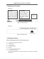
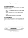
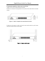
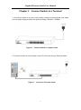
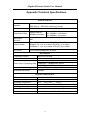
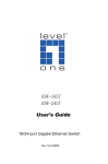
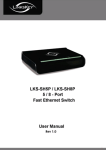
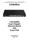
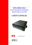
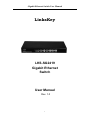
Gigabit Ethernet Switch User Manual LinksKey LKS-SG2419 Gigabit Ethernet Switch User Manual Rev. 1.0 1 Gigabit Ethernet Switch User Manual Safety Guidelines Observe the following to avoid any potential harm caused from improper use. For your safety, do not open the unit’s shell/outer case The unit operates correctly only within 100-240 AC voltage range rating To avoid potential short circuit and malfunction, do not expose the unit to humidity, heat, vibration or dust Operate it in a well-ventilated working environment 2 Gigabit Ethernet Switch User Manual Table of Contents Safety Guidelines ..................................................................................................... 2 Chapter 1 Overview ..................................................................................................................4 1.1 Product Overview ............................................................................................. 4 1.2 Features ............................................................................................................ 4 1.3 Appearance Overview ...................................................................................... 5 1.4 Package Contents ............................................................................................ 5 Chapter 2 Installation ...............................................................................................................6 2.1 Installation Considerations .............................................................................. 6 2.2 Installation Methods ......................................................................................... 6 Chapter 3 Connect Switch to a Terminal .............................................................................8 Chapter 4 Troubleshooting .....................................................................................................9 4.1. Power LED doesn’t light up. Check the following: ........................................ 9 4.2. Link/Act LED doesn’t light up. Problems and solutions may be: ................. 9 Appendix Technical Specifications ...................................................................................... 10 3 Gigabit Ethernet Switch User Manual Chapter 1 1.1 Overview Product Overview The Linkskey LKS-SG2419 Gigabit Ethernet Switch meets data transmission demands of Internet bar/enterprise in one cost-effective, rack mountable and green design. All 24 RJ45 ports support auto MDI/MDI-X, no need to worry about the cable type, simply plug and play. The Auto-negotiation on each RJ45 port senses link speed (10/100/1000Mbps) and duplex mode (full/half duplex mode) of its link partner and adjust itself for optimal performance. 1.2 Features Compliant with IEEE 802.3, IEEE 802.3u, IEEE 802.3ab, and IEEE 802.3az 24 x 10/100/1000M auto negotiation RJ45 Ports Backplane bandwidth up to 56Gbps for better throughput All ports support wire speed forwarding Auto MDI/MDI-X on each port IEEE 802.3x flow control in full duplex; Backpressure flow control in half duplex Built-in switch mode power supply for better stability Green design reduces energy consumption by up to 40% Low power consumption and fanless design saves noise interference Plug and play 19” rack mount 4 Gigabit Ethernet Switch User Manual 1.3 Appearance Overview Front Panel: Power LED: A solid light indicates switch has power while no light indicates switch is incorrectly connected to power outlet or there might be a problem with the power cord or outlet Link Act LED: A solid light indicates the corresponding port is correctly connected; a blinking light indicates the port is transferring data; no light indicates the port is disconnected or improperly connected RJ45 Ports Figure 1. Switch Front Panel Back Panel: Figure 2. Switch Back Panel 1.4 Package Contents Open the package and verify the following items: 1 x LKS-SG2419 Gigabit Ethernet Switch 1 x Power Cord 1 x User Manual 4 x Rubber Foot Pad 8 x Screw 2 x L-shaped Rack Mount Bracket 1 x Product Warranty Card (If any of the mentioned items is missing, contact your local reseller for immediate replacement.) 5 Gigabit Ethernet Switch User Manual Chapter 2 Installation 2.1 Installation Considerations To keep the switch in optimum working condition and prolong its lifetime, follow the instructions below for installation: 1. Please keep the switch in a dry and well ventilated environment to avoid possible poor stability due to excessive dust and humidity. 2. Place the unit in a safe and stable surface to avoid any possible damage from falling. 3. Ensure an over 10cm space around the switch for proper heat dissipation. 4. Do not put heavy articles on the Switch. 5. Make sure there is an over 1.5cm vertical distance between units that overlap each other. 6. Ensure operating power supply accords with rated input standard. 2.2 Installation Methods There are two ways to physically install the LKS-SG2419 24-port Gigabit Switch: Set the Switch on an operation desk and mount the Switch in a standard-sized, 19-inch rack. 1. To set the switch on an operation desk, do as follows: Correctly attach the included four rubber foot pads to switch’s bottom and then set it stably on the operation desk. Figure 3. Attach foot pad to Switch 6 Gigabit Ethernet Switch User Manual 2. To mount the switch in a 19-inch rack, do as follows: 1) Make sure the rack is stable and well grounded. 2) Attach the included mounting brackets to both sides of the switch with the included screws. Figure 4. Attach L-shaped rack mount bracket to switch 3) Maneuver the bracket to make sure that the slots match and line up with screw holes, then insert screws to fix the switch. Figure 5. Secure switch in rack 7 Gigabit Ethernet Switch User Manual Chapter 3 Connect Switch to a Terminal 1. Connect the switch to a power outlet nearby using the included power cord. Make sure the power supply accords with specified rating: 100-240V~ 50/60Hz. Figure 6. Connect switch to a power outlet 2. Connect a RJ45 port on the switch to the PC’s NIC port using an Ethernet cable. Figure 7. Connect a PC to the switch 8 Gigabit Ethernet Switch User Manual Chapter 4 Troubleshooting 4.1. Power LED doesn’t light up. Check the following: a) Check whether the power cord is correctly connected or not. b) Verify that power specification accords with specified rating. 4.2. Link/Act LED doesn’t light up. Problems and solutions may be: a) The switch is not correctly connected to the remote device. Please connect again with a new network cable. b) Network cable length is beyond the standard range. Please reduce the cable length between the switch and device to the standard range (The standard distance is 100 meters.) or try a shorter cable. 9 Gigabit Ethernet Switch User Manual Appendix Technical Specifications General Features Standard IEEE 802.3, IEEE 802.3u, IEEE 802.3ab, IEEE 802.3x, IEEE 802.3az(Energy saving) Protocol CSMA/CD Ethernet Transmission Rate Ethernet / Fast Ethernet Gigabit Ethernet 10 / 100Mbps(half duplex) 2000Mb(full duplex) 20 / 200Mbps(full duplex) Topological Structure Star Network Cable 10Base-T:Cat. 3 or better UTP/STP(up to 100m) 100Base-TX:Cat. 5 or better UTP/STP ( up to 100m) 1000Base-T:Cat. 5e or better UTP/STP (up to 100m) Port Count 24 x 10/100/1000Mbps RJ-45 Ports Key Features Forwarding Scheme Store-and-Forward MAC Address Table MAC Address Learning 8k 14880pps(10Mbps wire speed) 148800pps(100Mbps wire speed) 1488000pps(1000Mbps wire speed) Auto-learning / Auto-aging Backplane Bandwidth 56Gbps Packet Filter /Forwarding Rate Physical Characteristics AC Input Range Power Consumption Operating Temperature Storage Temperature Operating Humidity Storage Humidity Dimension 100 - 240VAC 50/60Hz 0.6A <15.4W 0°C ~ 40°C (32°F ~ 104°F) -40°C ~ 70°C (-40°F ~ 158°F) 10% ~ 90% RH Non-condensing 5% ~ 90% RH Non-condensing 440 x 178 x 44mm (17.3 x 7.0 x 1.7inch) 10 Gigabit Ethernet Switch User Manual FCC Statement This device complies with Part 15 of the FCC Rules. Operation is subject to the following two conditions: (1) This device may not cause harmful interference, and (2) this device must accept any interference received, including interference that may cause undesired operation. This equipment has been tested and found to comply with the limits for a Class A digital device, pursuant to Part 15 of the FCC Rules. These limits are designed to provide reasonable protection against harmful interference in a residential installation. This equipment generates, uses and can radiate radio frequency energy and, if not installed and used in accordance with the instructions, may cause harmful interference to radio communications. However, there is no guarantee that interference will not occur in a particular installation. If this equipment does cause harmful interference to radio or television reception, which can be determined by turning the equipment off and on, the user is encouraged to try to correct the interference by one of the following measures: - Reorient or relocate the receiving antenna. - Increase the separation between the equipment and receiver. - Connect the equipment into an outlet on a circuit different from that to which the receiver is connected. - Consult the dealer or an experienced radio/TV technician for help. FCC Caution: Any changes or modifications not expressly approved by the party responsible for compliance could void the user's authority to operate this equipment. This transmitter must not be co-located or operating in conjunction with any other antenna or transmitter. 11