1
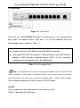
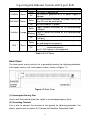
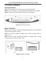
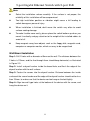
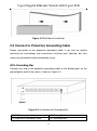
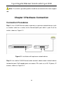
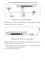
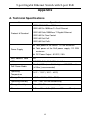
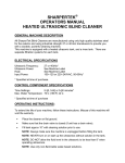
9-port Gigabit Ethernet Switch with 8-port PoE
LinksKey
LKS-SG9P8
9-port Gigabit
Ethernet Switch
with
8-port PoE
User Manual
Rev. 1.0
I
9-port Gigabit Ethernet Switch with 8-port PoE
Contents
Chapter 1 Introduction ........................................................................................ 1
1.1 Product Overview ................................................................................. 1
1.2 Package Contents ................................................................................ 1
1.3 Physical Description ............................................................................. 1
Front Panel ..................................................................................... 1
Back Panel...................................................................................... 3
Chapter 2 Installation........................................................................................... 4
2.1 Safety Precautions ............................................................................... 5
2.2 Site Requirements ................................................................................ 5
Operating Temperature and Humidity............................................. 5
Cleanness....................................................................................... 6
Lightning Protection ........................................................................ 6
Installation Site ............................................................................... 6
2.3 Installation Tools ................................................................................... 6
2.4 Product Installation............................................................................... 7
Desktop Installation ........................................................................ 7
Magnet Installation.......................................................................... 7
Wall Mount Installation.................................................................... 8
2.5 Connect to Protective Grounding Cable............................................... 9
With Grounding Bar ........................................................................ 9
Chapter 3 Hardware Connection ...................................................................... 10
Appendix............................................................................................................. 12
A. Technical Specifications ....................................................................... 12
B. Safety and Emission Statement ........................................................... 13
II
9-port Gigabit Ethernet Switch with 8-port PoE
Chapter 1 Introduction
1.1 Product Overview
The Linkskey LKS-SG9P8 Gigabit Ethernet with 8-port PoE Switch provides you
with an ideal seamless solution of high performance, low cost, easy-to-use, and
boosts your 10/100Mbps local area network to 1000Mbps. The switch supports
10/100/1000M auto-sensing, and protects the existing network investment when
you enjoy the gigabit network. The switch is plug-and-play with no configuration
required. Diagnostic LEDs which display link status and activity, allow you to
quickly detect and correct problems on the network. The LKS-SG9P8 also
provides eight PoE-capable ports of the switch, up to 30W output power on each
port, which can solve the problems resulting from wiring complexities, high cost
and maintenance difficulties of network devices.
1.2 Package Contents
Open the package and verify the following items carefully. If any of the listed items
is damaged or missing, please contact your local reseller.
1 x LKS-SG9P8 Gigabit Ethernet Switch with 8-port PoE
1 x Power Adapter
1 x User Manual
1 x Magnet Kit (4 magnets and 4 screws)
4 x Rubber Foot Pad
2 x Screw Set
1 x Product Warranty Card
1.3 Physical Description
Front Panel
The front panel mainly consists of RJ45 ports and LEDs, shown as Figure 1-1.
1
9-port Gigabit Ethernet Switch with 8-port PoE
(1) RJ45 Ports
Figure 1-1 Front Panel
There are nine 10/100/1000M RJ45 ports, of which port 9 is the Normal/Uplink
port, others are downlink ports. From port 1 to 8 of the downlink ports are
PoE-capable, details shown as Table 1-1.
PoE-capable Ports (1 ~ 8)
Compliant with the IEEE 802.3af and IEEE 802.3at standards
Up to eight IEEE 802.3af compliant (15.4W per port) or four IEEE 802.3at
compliant (30W per port) powered devices (PDs) can be accessed
simultaneously connected on any PoE-capable port
Table 1-1 PoE-capable Ports
Tips: PoE implements two ways of supplying DC power over the RJ45 Ethernet
cable. In Mode-A, is also known as "Phantom Power", the wire pairs which are used for
data transmission are also used to provide the power (Pair 1 and 2, Pair 3 and 6).
You’re recommended to use Cat.5 or higher UTP/STP cables.
(2) LED
You can check link status and activity of the switch via LEDs.
Table 1-2 describes the LED status.
2
9-port Gigabit Ethernet Switch with 8-port PoE
LED
Color
POWER
Green
PoE-MAX Green
Status
Description
Solid The switch is powered on
The switch is powered off or its power supply is
Off
improper
PoE consumption exceeds the power limit or no
Solid
more PDs can be powered on
Off
PoE consumption is proper
Proper network connection on the corresponding
RJ45 port
Solid
Link/Act
PoE
Orange Blinking Traffic is being transmitted on the corresponding
RJ45 port
No network connection is on the corresponding
Off
RJ45 port
Powered Device is connected to the corresponding
Solid
port and powered on properly
Green
Port 1 to 8 :Powered Device is powered off or not
Off
connected properly
Port 9 : PoE feature is not supported
Table 1-2 LED Status
Back Panel
The back panel mainly consists of a grounding terminal for lightning protection,
Kensington security slot, and a power socket, shown as Figure 1-2,
Figure 1-2 Back Panel
(1) Kensington Security Slot
Use an anti-theft lock to attach the switch to a fixed object against theft.
(2) Grounding Terminal
Use a wire to connect the terminal to the ground for lightning protection. For
details, please refer to section 2.5 Connect to Protective Grounding Cable.
3
9-port Gigabit Ethernet Switch with 8-port PoE
(3) Power Input Jack
Plug the DC power output to this power input jack to supply power for the switch.
Power Input
Power Output
100-240V AC, 50/60Hz
51V DC, 2.5A
Note: Please use only the power supply provided with the switch.
4
9-port Gigabit Ethernet Switch with 8-port PoE
Chapter 2 Installation
2.1 Safety Precautions
To avoid any device damage and bodily injury caused by improper use, please
observe the following rules.
Keep the power off during the installation
Wear an ESD-preventive wrist strap, and make sure that the wrist strap has a
good skin contact
Use only the power supply provided with the switch
Make sure that the supply voltage matches the specifications identified on the
power adapter provided with the switch
Ensure the vent hole is well ventilated and unblocked
Do not open or remove the housing of the switch
Before cleaning the switch, power off the power supply. Do not clean it by the
waterish cloth, and never use any other liquid cleaning method
Keep the switch away from nearest source of high voltage, such as power lines,
electric lamps, grids, etc.
Note: If needed to open the device’s housing, please contact Linkskey to get
permission, or you have to be responsible for the result that the device cannot be
maintained because of unpermitted operation.
2.2 Site Requirements
Operating Temperature and Humidity
Requirements of temperature and humidity to the switch are shown as Table 2-1.
Environment
Temperature
Humidity
Operating
14ºF ~ 113ºF (-10ºC ~ 45ºC) 10% ~ 90% RH (Non-condensing)
Storage
-40ºF ~ 158ºF (40ºC ~ 70ºC)
5% ~ 90% RH (Non-condensing)
Table 2-1 Temperature and Humidity Requirement
5
9-port Gigabit Ethernet Switch with 8-port PoE
Cleanness
To avoid the effect of static electricity on the operation of the switch, please refer to
the followings:
Dust the switch regularly, and keep the indoor air clean
Keep the switch well-grounded and ensure static electricity has been
transferred
Lightning Protection
To avoid the damage of electronic devices made by the extremely high voltage
current produced when lightning occurs, please take the following lightning
protection measures.
Ensure the rack and the switch’s ground terminal are well earthed
Make sure the power outlet has a good contact with the ground
Keep a reasonable cabling system to avoid induced lightning
Use the signal SPD (Surge Protective Device) when wiring outdoor
Installation Site
When installing the device on a rack or a flat workbench, please note the following
items.
Make sure that the rack or workbench is sturdy enough to support the switch
and well-grounded
Make sure that the switch has a good ventilation system. The device should be
left 10cm of equipment clearance for ventilation
Do not place objects on the switch
If the switches need to be used in stacked, the vertical distance between
neighboring ones cannot be less than 1.5 cm
2.3 Installation Tools
Phillips Screwdriver
ESD-preventive Wrist Wrap
Network Cables (Option)
6
9-port Gigabit Ethernet Switch with 8-port PoE
2.4 Product Installation
Desktop Installation
Step 1: Set the bottom of the switch up on a flat and stable desktop.
Step 2: Paste four cushions in the corresponding concave places at the bottom.
Step 3: Turn over the switch and place it face up on the workbench.
Figure 2-1 Desktop Installation
Magnet Installation
Step 1: Attract 4 magnets into the corresponding round grooves on the bottom at
each corner of the switch’s housing.
Step 2: Use screws to secure the magnets to the switch’s housing, shown as
Figure 2-2 (a).
Step 3: Press the switch (installed with magnets) in a proper way on a stable
surface you select, shown as Figure 2-2 (b).
Figure 2-2 Magnet Installation
7
9-port Gigabit Ethernet Switch with 8-port PoE
Note:
Select the installation surface carefully. If the surface is not proper, the
Too high installation position or vibration might cause a fall leading to
reliability of this installation will be compromised
switch damage or personal injury
When installation is finished, don't move the switch very often to avoid
surface coating damage
To make it cable more easily, please place the switch bottom up when you
mount it vertically and pay attention to the weight of the installed cables to
avoid a fall
Keep magnets away from objects such as the floppy disk, magnetic card,
computer or computer monitor, which are easy to be magnetized
Wall Mount Installation
Step 1: Drill 2 holes with a diameter of 5mm on the wall. The distance between the
2 holes is 110mm, and the line through them should keep horizontal, as illustrated
in Figure 2-3.
Step 2: Install a drywall anchor inside the board hole; and flush the edge of the
drywall anchor with the wall surface.
Step 3: Fasten the screws into the drywall anchor. Distance between the inside
surface of the screw header and the edge of the drywall anchor should not be less
than 2.5mm, to make sure that the device can be hung on the bolt tightly.
Step 4: Align two wall type holes at the bottom of the device with the screw, and
hang the device on it.
8
9-port Gigabit Ethernet Switch with 8-port PoE
Figure 2-3 Wall Mount Installation
2.5 Connect to Protective Grounding Cable
Proper connection of the protective grounding cable is not only for quickly
releasing the overvoltage and overcurrent resulting from lightning, but also
necessary precaution of preventing bodily injury.
With Grounding Bar
Connect one end of the protective grounding cable to the binding post on the
grounding bar and fix the screws, shown as Figure 2-4
Figure 2-4 Installation with Grounding Bar
(1) DC Power Input Jack
(3) Protective Grounding Cable
(2) Binding Post
(4) Grounding Bar
9
9-port Gigabit Ethernet Switch with 8-port PoE
Note: The switch’s grounding cable should be connected to the metal support
rod.
Chapter 3 Hardware Connection
Connection Procedures
Step 1: Use a RJ45 Ethernet cable to connect an upstream network device (such
as another switch or a router) to the Normal/Uplink port which is port 9 on the
switch, shown as Figure 3-1.
Figure 3-1 Installation with upstream network device
Step 2: Use another RJ45 Ethernet cable connect a downstream network device
to downlink port. PoE-capable ports can access PDs such as an AP, IP phone, IP
camera, shown as Figure 3-2.
10
9-port Gigabit Ethernet Switch with 8-port PoE
Figure 3-2 Installation with Powered Devices
Step 3: Use the AC power adapter provided in the product package to supply
power for the switch, shown as Figure 3-3.
Figure 3-3 Installation with the AC power adapter
Step 4: After powered up, the switch begins auto-initialization. Check the LED
indicators, and they will respond as follows:
All the functional LEDs will flash momentarily for one second and then go off,
which represents a resetting of the system.
The POWER LED indicator is lit.
11
9-port Gigabit Ethernet Switch with 8-port PoE
Appendix
A. Technical Specifications
Item
Specification
IEEE 802.3i 10Base-T Ethernet
IEEE 802.3u 100Base-Tx Fast Ethernet
Protocol & Standard
IEEE 802.3ab 1000Base-T Gigabit Ethernet
IEEE 802.3x Flow Control
IEEE 802.3af PoE
IEEE 802.3at PoE+
Total power of the switch: 127.5W maximum
Power Supply
Total power of the PoE power supply: 121.22W
maximum
DC Power Output : 51VDC, 2.5A
MAC Address Table
4K
LEDs
POWER, PoE , PoE-MAX , Link/Act
PoE Power Media
Operating
Temperature
Cat.5 (≤100m) or Cat.5 higher UTP/STP cables
(≤150m) (recommended)
14ºF ~ 113ºF (-10ºC ~ 45ºC)
Storage Temperature
-40ºF ~ 158ºF (-40ºC ~ 70ºC)
Operating Humidity
10% ~ 90% RH non-condensing
Storage Humidity
5% ~ 90% RH non-condensing
Dimension
9.3in x 4.0in x 1.0in (235mm x 103mm x 27mm)
12
9-port Gigabit Ethernet Switch with 8-port PoE
B. Safety and Emission Statement
CE Mark Warning
This is a Class A product. In a domestic environment, this product may cause
radio interference, in which case the user may be required to take adequate
measures.
NOTE: (1) The manufacturer is not responsible for any radio or TV interference
caused by unauthorized modifications to this equipment. (2) To avoid unnecessary
radiation interference, it is recommended to use a shielded RJ45 cable.
FCC Statement
This equipment has been tested and found to comply with the limits for a Class A
digital device, pursuant to part 15 of the FCC Rules. These limits are designed to
provide reasonable protection against harmful interference when the equipment is
operated in a commercial environment. This equipment generates, uses, and can
radiate radiofrequency energy and, if not installed and used in accordance with the
instruction manual, may cause harmful interference to radio communications.
Operation of this equipment in a residential area is likely to cause harmful
interference in which case the user will be required to correct the interference at
his/her own expense.
FCC Caution: Any changes or modifications not expressly approved by the party
responsible for compliance could void the user's authority to operate this
equipment.
This device complies with part 15 of the FCC Rules. Operation is subject to the
following two conditions: (1) This device may not cause harmful interference, and
(2) this device must accept any interference received, including interference that
may cause undesired operation.
NOTE: (1) The manufacturer is not responsible for any radio or TV interference
caused by unauthorized modifications to this equipment. (2) To avoid unnecessary
radiation interference, it is recommended to use a shielded RJ45 cable.
13