1
DESKTOP ENGRAVER
EGX-20
US E R' S
MA N U A L
Thank you very much for purchasing the EGX-20.
•
To ensure correct and safe usage with a full understanding of this product's performance, please be sure
to read through this manual completely and store it
in a safe location.
•
Unauthorized copying or transferral, in whole or in
part, of this manual is prohibited.
•
The contents of this operation manual and the specifications of this product are subject to change without notice.
•
The operation manual and the product have been prepared and tested as much as possible. If you find
any misprint or error, please inform us.
•
Roland DG Corp. assumes no responsibility for any
direct or indirect loss or damage which may occur
through use of this product, regardless of any failure to perform on the part of this product.
For the USA
FEDERAL COMMUNICATIONS COMMISSION
RADIO FREQUENCY INTERFERENCE
STATEMENT
This equipment has been tested and found to comply with the
limits for a Class A digital device, pursuant to Part 15 of the
FCC Rules.
These limits are designed to provide reasonable protection
against harmful interference when the equipment is operated
in a commercial environment.
This equipment generates, uses, and can radiate radio
frequency energy and, if not installed and used in accordance
with the instruction manual, may cause harmful interference
to radio communications.
Operation of this equipment in a residential area is likely to
cause harmful interference in which case the user will be
required to correct the interference at his own expense.
Unauthorized changes or modification to this system can void
the users authority to operate this equipment.
The I/O cables between this equipment and the computing
device must be shielded.
For Canada
CLASS A
NOTICE
This Class A digital apparatus meets all requirements of the
Canadian Interference-Causing Equipment Regulations.
CLASSE A
AVIS
Cet appareil numérique de la classe A respecte toutes les
exigences du Règlement sur le matériel brouilleur du
Canada.
ROLAND DG CORPORATION
1-6-4 Shinmiyakoda, Hamamatsu-shi, Shizuoka-ken, JAPAN 431-2103
MODEL NAME
: See the MODEL given on the rating plate.
RELEVANT DIRECTIVE : EC MACHINERY DIRECTIVE (98/37/EC)
EC LOW VOLTAGE DIRECTIVE (73/23/EEC)
EC ELECTROMAGNETIC COMPATIBILITY DIRECTIVE (89/336/EEC)
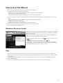
How to Use This Manual
Be sure to read through this manual when using the EGX-20 for the first time.
This manual explains mainly the following information.
• Connecting to a computer, installing a blade, mounting an engraving workpiece, and the like
• Installing the driver software on the computer
• The procedure for creating a nameplate using Dr. Engrave (a text-engraving program)
You can also install and set up the following programs on the included Roland Software Package CD-ROM and use them on your
computer.
• Virtual MODELA (a program that simulates cutting results obtained with 3D Engrave)
• Dr.Engrave (a text-engraving program)
• 3D Engrave (a program for creating reliefs)
• Windows driver (a software driver for using the EGX-20 with Windows)
The manuals for these (except for the manual for the driver) are in electronic format.
Refer to them for detailed information on use.
Manuals in Electronic Format
You can view the manuals in electronic format (PDF files) from the setup menu that
appears when you insert the Roland Software Package CD-ROM in the CD-ROM
drive on your computer.
Load the Roland Software Package CD-ROM in the computer's CD-ROM drive
and view the manuals in electronic format as required.
To view a description of the program, click the
button. To view a manual, click
the
button.
A PDF manual is available for programs listed with a button.
Acrobat Reader is required to view PDF files. If Acrobat Reader is not already
installed and set up on your computer, then the setup program for Acrobat Reader
starts automatically, allowing you to install and set it up.
Help
After you have installed and set up the programs, you can view help for each that contains information similar to the PDF files.
In Windows, click [Start]. From the menu, point to [Programs], then [Roland 3D Engrave], then select [3D Engrave Help]. The help
window appears.
In the same way, point to [Roland Dr. Engrave] and select [Dr. Engrave Help], or point to [Roland Virtual MODELA] and select
[Virtual MODELA Help].
Alternatively, start the respective program, then from the [Help] menu, select [Contents]. The help window appears.
1
Table of Contents
How to Use This Manual ............................................................................................................... 1
To Ensure Safe Use ........................................................................................................................ 3
About the Labels Affixed to the AC Adapter and Unit .................................................................. 5
1. Getting Ready .................................................................................................. 6
What You Can Do with the EGX-20 .............................................................................................. 6
Check the Included Items ............................................................................................................... 6
Names and Functions ..................................................................................................................... 7
Setting Up and Connection ............................................................................................................ 8
Attaching the Adhesive Sheet ........................................................................................................ 10
Installing the Cutter Holder ........................................................................................................... 11
2. Installing and Setting Up the Software ......................................................... 12
3. Creating a Nameplate (Engraving Mode) ...................................................... 16
Loading Material ............................................................................................................................ 16
Installing a Cutter ........................................................................................................................... 17
Setting the Origin Point .................................................................................................................. 19
Creating Data with Dr. Engrave ..................................................................................................... 20
Setting the Cutting Parameters ....................................................................................................... 25
Performing Engraving .................................................................................................................... 27
4. Creating a Relief (3D Cutting Mode) .............................................................. 28
Removing the Cutter ...................................................................................................................... 28
Detaching the Depth Regulator Unit ............................................................................................. 29
Installing a Cutter ........................................................................................................................... 30
Loading Material ............................................................................................................................ 31
Setting the Origin Point .................................................................................................................. 32
Creating Data with 3D Engrave ..................................................................................................... 34
Adjusting Cutting ........................................................................................................................... 37
Performing Cutting ......................................................................................................................... 38
5. More Advanced Operations ............................................................................ 39
Using Different Nose Cones for Different Purposes ..................................................................... 39
Using the 3D Cutting Mode ........................................................................................................... 40
6. Optional Parts .................................................................................................. 42
Replacement Cutters and Consumable Parts ................................................................................. 42
Optional Parts for Scribing ............................................................................................................ 43
7. Appendix .......................................................................................................... 44
Daily Care and Maintenance .......................................................................................................... 44
Functions Using the Switch Panel on the EGX-20 ........................................................................ 44
What to Do If... .............................................................................................................................. 45
Specifications ................................................................................................................................. 47
Windows® and Windows NT® are registered trademarks or trademarks of Microsoft® Corporation in the United States and/or other countries.
Adobe and Acrobat are trademarks of Adobe Systems Incorporated.
Pentium is registered trademarks of Intel Corporation in the United States.
Other company names and product name are trademarks or registered trademarks of their respective holders.
Copyright © 2002 Roland DG Corporation
2
http://www.rolanddg.com/
To Ensure Safe Use
About
and
Notices
Used for instructions intended to alert the user to the risk of death or severe
injury should the unit be used improperly.
Used for instructions intended to alert the user to the risk of injury or material
damage should the unit be used improperly.
* Material damage refers to damage or other adverse effects caused with
respect to the home and all its furnishings, as well to domestic animals or
pets.
About the Symbols
The
symbol alerts the user to important instructions or warnings. The specific meaning of
the symbol is determined by the design contained within the triangle. The symbol at left means
"danger of electrocution."
The
symbol alerts the user to items that must never be carried out (are forbidden). The
specific thing that must not be done is indicated by the design contained within the circle. The
symbol at left means the unit must never be disassembled.
The
symbol alerts the user to things that must be carried out. The specific thing that must
be done is indicated by the design contained within the circle. The symbol at left means the
power-cord plug must be unplugged from the outlet.
Do not disassemble, repair, or
modify.
Ground the unit with the ground
wire.
Doing so may lead to fire or abnormal
operation resulting in injury.
Failure to do so may result in risk of
electrical shock in the even of a mechanical
problem
Do not use with any electrical power
supply that does not meet the
ratings displayed on the AC adapter.
Do not use with any power supply
other than the dedicated AC adapter.
Use with any other power supply may lead
to fire or electrocution.
Do not use while in an abnormal
state (i.e., emitting smoke, burning
odor, unusual noise, or the like).
Doing so may result in fire or electrical
shock.
Immediately unplug the power-cord plug
from the electrical outlet, and contact your
authorized Roland DG Corp. dealer or
service center.
Use with any other power supply may lead
to fire or electrocution.
Use only with the power cord
included with this product.
Use with other than the included power cord
may lead to fire or electrocution.
3
Do not use with a damaged AC
adapter, power cord, or power-cord
plug or with a loose electrical outlet.
Use with any other
power supply may
lead to fire or
electrocution.
Do not injure or modify the electrical
power cord, nor subject it to
excessive bends, twists, pulls,
binding, or pinching, nor place any
object of weight on it.
Doing so may
damage the
electrical power
cord, leading to
electrocution or
fire.
When not in use for several hours,
unplug the power-cord plug from the
electrical outlet.
When unplugging the electrical
power cord from the power outlet,
grasp the plug, not the cord.
Failure to do so may
result in danger of
shock, electrocution,
or fire due to
deterioration of the
electrical insulation.
Unplugging by
pulling the cord
may damage it,
leading to fire or
electrocution.
Do not attempt to unplug the powercord plug with wet hands.
Do not allow liquids, metal objects
or flammables inside the machine.
Doing so may
result in electrical
shock.
Such materials
can cause fire.
Install on a stable surface.
Do not touch the tip of the blade
with your fingers.
Failure to do so
may result in
falling of the unit,
leading to injury.
Doing so may result in injury.
Do not inadvertently allow the
hands, or hair near the rotating parts
while in operation.
Doing so may result in injury.
Wear dust goggles and mask during
use.
When you're finished,
wash your hands to
rinse away all
cuttings.
4
Cutting dust
may scatter,
causing bodily
injury.
About the Labels Affixed to the AC Adapter and Unit
These labels are affixed to the body of this product and the AC adapter. The following figure describes the location.
Handle tool with care.
Model name
Rating label
Do not use with any electrical power supply
that does not meet the ratings displayed on
the AC adapter.
In addition to the
NOTICE
and
symbols, the symbols shown below are also used.
: Indicates information to prevent machine breakdown or malfunction and ensure correct use.
: Indicates a handy tip or advice regarding use.
5
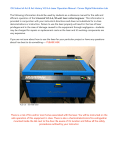
EGX-20 USER'S MANUAL
1 Getting Ready
What You Can Do with the EGX-20
• You can engrave a plate with text or shapes to create a nameplate or the like.
Using Dr. Engrave, the included 2D engraving program, you can easily engrave anything from simple text to complex
designs to produce high-quality engraved plates.
p. 16 "Creating a Nameplate"
• You can cut thick materials up to a depth of 7 mm to create reliefs and other forms.
Using 3D Engrave, the included 3D engraving program, you can easily produces reliefs and other three-dimensional engraved forms.
p. 28 "Creating a Relief"
Check the Included Items
AC adapter: 1
Power cord: 1
Cutter: 1
(with cutter holder)
Nose cones
(large: 1, medium: 1, small: 1)
Adhesive sheet: 1
Test-use plate material: 1
Hexagonal wrenches
(large: 1 and small: 1)
User's Manual: 1
The medium one is installed on the
machine.
Hexagonal screw driver: 1
Roland Software Package
CD-ROM: 1
6
1. Getting Ready
Names and Functions
The names of the parts of the EGX-20 are as follows.
Front
Cover
Carriage
Switch Panel
Spindle unit
Spindle motor
Z-axis light
Movement button
Speed control
Power light
View light
Origin Set light
Spindle Speed
control
Power button
View button
Origin Set button
Table
Depth regulator unit
Rear
Parallel connector
AC adapter jack
7
EGX-20 USER'S MANUAL
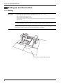
Setting Up and Connection
Setting
NOTICE
Never install this unit in any of the following situations, as it could result in damage:
• Places where the installation surface is unstable or not level.
• Places with excessive electrical noise.
• Places with excessive humidity or dust.
• The EGX-20 generates heat when used, and should not be installed in an area with poor heat radiation
characteristics.
• Places with excessive vibration.
Use within a temperature range of 5 to 40°C (41 to 104°F) and within a humidity range of 35 to 80%.
Securely connect the power cord, computer I/O cable and so on so that they will not be unplugged and cause
failure during operation. Doing so may lead to faulty operation or breakdown.
30 cm
10 c
m (4
(12 in
.)
in.)
30 c
m (1
10 c
2 in
.)
m (4
in.)
* Do not place any object within the area
8
1. Getting Ready
Connecting the AC Adapter and Power Cord
Connect in the order of the numbers shown in the figure.
1
AC adapter jack
2
AC adapter
Power cord
3
Connecting to the Computer
To connect the machine and the computer, you can use either a parallel cable (IEEE 1284-compliant) .
The parallel cable is sold separately. Use a cable suited to the configuration of the printer port on your computer.
NOTICE
Make the cable connections while the computer and the machine are switched off.
Amphenol 36-pin connector
Computer
Printer port
9
EGX-20 USER'S MANUAL
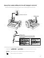
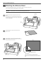
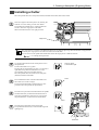
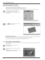
Attaching the Adhesive Sheet
You use the included adhesive sheet to secure material to engrave to the table on the EGX-20.
First you need to install the included adhesive sheet on the table.
NOTICE
Be sure the unit is in View status when attaching the adhesive sheet.
Carriage
11
Press the power button on the EGX-20 to turn on the
power.
The carriage moves to the right edge and the table moves
to the front, the unit goes into View status, and the Power
and View lights light up.
EGX-20
Table
22
Peel off the protective paper from both sides of the
adhesive sheet.
33
Place the adhesive sheet on the table as shown in the
figure at right, press down on it from above, and secure it
in place so that it will not peel off.
Table
EGX-20
Adhesive sheet
Adhesive sheet
10
There are holes at the four corners of the table.
Align the corner of the adhesive sheet with the lower-left
hole.
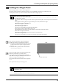
1. Getting Ready
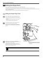
Installing the Cutter Holder
Before you install a cutter, you need to install the included cutter holder on the spindle unit.
11
A cutter holder is attached to the included cutter.
Remove the cutter from the cutter holder.
Cutter
22
Open the cover for the carriage.
3
Orient the cutter holder so that the screw is underneath,
insert the cutter holder into the spindle unit from above,
then turn the cutter holder counterclockwise by hand to
secure it in place.
The spindle unit moves when you do this, so insert the
included hexagonal screwdriver into the hole in the
spindle unit as shown in the figure to keep it from
moving.
Cutter holder
Open the cover for the carriage.
The cutter holder is reverse-threaded.
Turn it counterclockwise to tighten.
11
EGX-20 USER'S MANUAL
2 Installing and Setting Up the Software
To use the EGX-20, you need to install the driver on the computer connected to the EGX-20. The EGX-20 also comes with a
number of programs for creating engraving and cutting data, which you can use to match the target task. To use these programs,
you need to install and set them up on the computer connected to the EGX-20.
The Software You Can Install and Set Up
The drivers and programs are contained on the Roland Software Package CD-ROM. Be sure to install the Windows driver. Install
and set up the other software, the programs, as required. You can use the following drivers and programs with the EGX-20.
Driver or program
Overview
Windows driver
This is necessary when sending data from a program running under Windows to the EGX-20. Be sure to
install it.
Virtual MODELA
This uses data created with 3D Engrave to perform simulations before cutting with the EGX-20.
You can use it to check the finished shape as well as things like whether the cutting depth is suitable and
how much time cutting will take. This can reduce loss for cutting materials and time.
Dr. Engrave
This is used to design text and shapes to engrave on a plate and to send the data to the EGX-20.
You can use the TrueType fonts registered in Windows as the font style for text. You can even make
stroke fonts from TrueType fonts.
Because you can the outline of an image and convert it to line segments, it's also possible to include
logos for companies or organizations in the plates you make.
3D Engrave
This adds thickness to a flat (two-dimensional) graphic to create a relief (raised engraving).
You can also add thickness to figures and other images.
System Requirements
The following operating environment is required in order to use the drivers and programs just described. Make sure your system
configuration meets these requirements.
Operating system
Windows 95/98/Me/NT 4.0/2000/XP
Computer
Computer running Windows (Pentium processor or better recommended)
Drive
CD-ROM drive
Monitor
Windows-compatible monitor capable of displaying 256 colors or more
Memory
32 MB or more recommended
Free hard-disk space
required for installation
25 MB (combined total for Dr. Engrave, 3D Engrave, and Virtual MODELA)
Interface
Printer port
Installation and Setup
NOTICE
If the computer and the EGX-20 are already connected, then switch off the power to the EGX-20 before you
perform installation and setup.
Installation and set up under Windows 2000/NT 4.0/XP require full access rights for the printer settings.
Log on to Windows as a member of the "Administrators" or "Power Users" group. For more information about
groups, refer to the documentation for Windows.
12
2. Installing and Setting Up the Software
Follow the steps below to install and set up the driver and programs.
1
Turn on the computer and start Windows.
If you're running a virus-detection program, then quit the
program. Also quit all running programs except Windows. In Windows, make sure no program icons appear
on the taskbar, then go on to the next step.
2
Insert the included CD-ROM into the CD-ROM drive.
The setup menu appears automatically.
3
Click the drop-down arrow for [Click here], then from
the menu that appears, select [EGX-20].
If the setup menu does not appear automatically
even when the included CD-ROM is loaded in the
CD-ROM drive, then use Windows Explorer to
select the CD-ROM drive, then double-click
"CDMenu.exe" to run it.
If your computer is connected to the Internet,
the Roland DG Corp. website appears.
Check this for information about updates to
the driver and the like.
4
The programs you can install and set up with the EGX20 appear.
You can view a description for each program by clicking
the
button next to the corresponding program name.
Also, to display the Readme file, click the [Readme]
button. This lets you read the latest information that
could not be included in the user's manual. Please be sure
to read it before use.
This document does not contain manuals for the programs, but a manual in PDF format is available for each
program shown with a button. Click the button to display the PDF manual.
Acrobat Reader is required to view PDF files. If Acrobat Reader is not already installed and set up on your computer, then the setup program for Acrobat Reader on the included CD-ROM starts automatically, allowing you to
install and set it up.
13
EGX-20 USER'S MANUAL
5
You can choose to install and set up a program by
selecting its corresponding check box.
If you do not want to install a particular program, than
clear the corresponding check box.
Normally you should select all check boxes.
Click the [Install] button.
6
The setup screen ([Welcome] dialog box) appears for the
program whose check box you selected.
If you selected the check boxes for all programs, then the
setup screens appear in succession, starting with Virtual
MODELA.
Click [Next].
7
The [Select Install Location] dialog box appears.
If you want to change the folder to install to, then click
[Browse]. The [Select Directory] dialog box appears.
Choose a drive and folder, then click [OK].
Click [Next].
8
The [Select Program Folder] dialog box appears.
There is no special need to change the program folder.
After you have made sure of the program folder, click
[Next].
Installation starts.
9
When installation finishes, a prompt dialog box appear.
Click [OK].
When the installation of one program finishes, installation of the next one starts.
In the interval until the next setup starts, a dialog box
showing the progress of processing is displayed.
14
2. Installing and Setting Up the Software
10
The setup screen ([Welcome] dialog box) appears for the
next program to install.
Carry out steps 6 through 9 on the previous page.
Install Dr. Engrave and 3D Engrave.
11
When installation of 3D Engrave finishes, the [EGX-20
Driver Installation] dialog box appears.
Choose the port for connecting the EGX-20.
The EGX-20 connects to a printer port. If your computer
has a single printer port, select [LPT1:].
Click [OK].
The EGX-20 driver is installed.
12
When installation of the EGX-20 driver finishes, the
[Settings: [EGX-20]] dialog box appears.
Make sure the values are correct, then click [Close].
13
When all installation and setup finishes, a prompt dialog
box appears. Click [Close].
14
When the setup menu screen reappears, click the
button.
15
Take the CD-ROM out of the CD-ROM drive.
15
EGX-20 USER'S MANUAL
3 Creating a Nameplate (Engraving Mode)
This section describes the basic steps for engraving using the EGX-20, taking the procedure for engraving the plate included
with the machine as an example.
NOTICE
Large changes in temperature may alter the cutting depth. Use care when using near an air conditioner or
heater. In cases like this, reinstall the cutter (thereby realigning it with the reference surface).
Cuttable depth is 0.05 to 1 mm (0.002 to 0.039 in.) in the Engraving mode. Do not attempt cutting that
exceeds this depth.
In the engraving mode, fill engraving over a broad area (that is, having a width equal to or greater than the
diameter of the nose cone) cannot be performed. Such operations are generally classified as "difficult"
engraving, but they are possible using the 3D cutting mode.
p. 39 "Using Different Nose Cones for Different Purposes" , p. 40 "Using the 3D Cutting Mode"
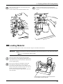
Loading Material
You use the included adhesive sheet to secure material to engrave to the table on the EGX-20.
NOTICE
When you load more than one plate at a time, make sure there are no gaps between them. Plates that are not
quadrilateral or are of irregular shape may not be suitable for engraving with the EGX-20.
Before you load material, attach the included adhesive sheet. Be sure the unit is in View status when loading
material.
p. 10 "Attaching the Adhesive Sheet"
1
If the EGX-20 is switched off, press the power button to
turn it on.
The carriage moves to the right edge and the table moves
to the front, the unit goes into View status, and the Power
and View lights light up.
If the EGX-20 is turned on but the View light is not
illuminated, press the View button.
The carriage moves to the right edge and the table moves
to the front, the unit goes into View status, and the Power
and View lights light up.
2
Place the plate on the adhesive sheet, then press down on
it from above to anchor it securely.
You can place the item anywhere on the adhesive sheet.
However, if the plate is placed at an angle with respect to
the table, the engraving will not be straight.
Place it so that it is aligned straight with the corners and
sides of the table.
Place the plate on the adhesive sheet, then press
down on it from above to anchor it securely.
16
Power and View
lights illuminate.
EGX-20
3. Creating a Nameplate (Engraving Mode)
Installing a Cutter
Move the spindle unit to above the plate (material) mounted on the table, then install a cutter.
1
If the View light on the switch panel is lit (showing the
machine is in View status), press the View button.
The spindle unit and table move, and the spindle unit
moves to above the origin point on the table.
When movement ends, the View light goes dark.
Origin Point
The origin point is a reference point that the EGX-20 uses for starting engraving. When the machine is shipped from
the factory, the origin point is set at the lower left corner of the table.
You can also move the spindle unit and the table and set the origin point at a different location.
p. 19 "Setting the Origin Point"
2
Use the movement button on the switch panel to move
the spindle unit.
The movement button is a joystick.
Pressing the movement button up, down, or to the left or
right makes the spindle unit and table move in the
corresponding vertical or horizontal direction.
Move the spindle unit to about the center of the plate
(material) mounted on the table.
3
Press and hold the center of the movement button for
short while (0.6 second or longer).
The Z-axis light illuminates, indicating that it is now
possible to move the spindle unit up and down.
4
Press the lower part of the movement button. The spindle
unit descends while you hold down the button. Movement stops automatically when the nose cone contacts
the plate (material), so release the movement button.
Press up, down,
or to the left or right.
Press.
Press.
5
Press the Origin Set button on the switch panel.
The spindle unit descends by 0.5 mm and the Origin Set
light lights up.
Press.
Nose cone
17
EGX-20 USER'S MANUAL
6
Insert the cutter into the hole in the cutter holder, then
slowly lower the cutter.
Lower until the cutter touches the plate.
NOTICE
Before you install a cutter, install the cutter holder.
p. 11 "Installing the Cutter Holder"
7
Use the included hexagonal screwdriver to tighten the
retaining screw for the cutter holder.
Tighten secure so that the cutter does not come loose
during engraving.
8
Press the Origin Set button on the switch panel.
The spindle unit rises 0.5 mm and the Origin Set light
goes dark.
Press.
18
3. Creating a Nameplate (Engraving Mode)
Setting the Origin Point
When loading material, be sure to set the origin point.
The origin point is the reference point for engraving. You set it individually for each piece of material you load.
Omitting this operation may result in locations other than the material being engraved.
Basic Steps for Moving the Spindle Unit
When you installed the cutter in the spindle unit, you performed operations to move the spindle unit. These steps
can be summed up as follows.
• The operation differs according to whether the View light and Z-axis light on the switch panel are illuminated or
dark.
• Changing between the lighted View light (indicating View status) and dark View light
Press the View button on the switch panel.
• When the View light is illuminated
You cannot move the spindle unit.
• When the View light is dark
You can move the spindle unit using the movement button.
• Changing between the lighted and dark Z-axis light
Press and hold the center of the movement button for a short while (0.6 second or more).
• When the Z-axis light is illuminated
You can move the spindle unit up and down using the movement button.
• When the Z-axis light is dark
You can move the spindle unit vertically or horizontally using the movement button.
1
Refer to the preceding "Basic Steps for Moving the
Spindle Unit" and move the spindle unit as follows.
1. If the cutter is touching the plate (material), move the
spindle unit upward to separate it slightly from the
material.
2. Move the cutter to position it above the lower left
corner of the plate (material).
2
If the Z-axis light is dark, press and hold the Origin Set
button for a short while (0.3 second or more).
(Pressing the Origin Set button lights the Origin Set
light. Make sure the light is illuminated, then release the
button. The Origin Set light goes dark.)
The vertical and horizontal locations of the origin point
are set.
Plate
Center of the cutter
This completes the setting for the origin point.
Pressing the Origin Set button while the Z-axis light is lit lowers the spindle unit and puts the machine in the state
for installing a cutter.
When you are engraving a nameplate, there is no need to set a height-location origin point. The sensors automatically detect the surface location of the plate (material).
19
EGX-20 USER'S MANUAL
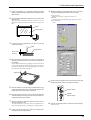
Creating Data with Dr. Engrave
This section describes the basic steps for engraving a nameplate using Dr. Engrave.
The following explanation is for Windows 95/98/Me.
For an explanation for Windows NT 4.0/2000/XP, or for a more detailed explanation, see the help for Dr. Engrave or
refer to the Dr. Engrave User's Manual (PDF) on the Roland Software Package CD-ROM.
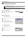
Starting Dr. Engrave
1
In Windows, click the [Start] button. At the Start menu,
point to [Programs], then [Roland Dr. Engrave]. At the
menu that appears, click [Dr. Engrave].
Dr. Engrave starts.
Specifying the Size of the Plate to Engrave
Make the size of the engraving area displayed by Dr. Engrave the same as the size of the actual plate to engrave.
This is analogous to choosing the form size in a word-processing program.
1
In Dr. Engrave, from the [File] menu, select [Print
Setup].
2
The [Print Setup] dialog box appears.
Make sure the printer name is set to [Roland EGX-20] (if
the printer name is not [Roland EGX-20], then click the
drop-down arrow and select [Roland EGX-20]), then
click [Properties].
3
The [Roland EGX-20 on LPT1: Properties] dialog box
appears.
Measure the size of the plate to engrave with a ruler or
the like, type in the values in the [Width] and [Length]
entry boxes, then click [OK].
4
The [Print Setup] dialog box appears again, then click
[OK].
The engraving area that Dr. Engrave displays is shown at
the size you specified.
20
3. Creating a Nameplate (Engraving Mode)
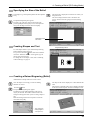
Entering Text
Enter the text to engrave on the plate.
.
1
At the toolbar, click
2
Click the location in the engraving area where you want
to type in text, then enter the text using the keyboard.
Engraving area
Selecting the Font
Specify a font for the text string you entered.
Character cursor
1
At the toolbar, click , then click the text string whose
font you want to change.
The character cursor appears in the text string.
Alternatively, at the toolbar click , then click the text
string whose font you want to change.
Points appear around the text string.
2
From the [Format] menu, select [Font].
Points
Click a font name.
3
The [Font Select] dialog box appears.
Clicking a font name displays the text in the preview
field with the font you chose, allowing you to find the
font you want.
4
After you have selected the font you want, click [OK].
Preview
In the [Font Select] dialog box, font names that start with "Plot" are stroke fonts.
p. 24 "Stroke Fonts"
21
EGX-20 USER'S MANUAL
Working with Text Strings
You can resize and deform a text string by manipulating the points displayed around the string.
Resizing and Moving
1
At the toolbar, click , then click the text string.
Points appear around the text string.
2
You can change the size of the text string by lining up
the pointer with a point and dragging.
You can change the size while keeping the vertical/
horizontal aspect unchanged by holding down the [Shift]
key on the keyboard as you drag the point ( ).
You can change the size by dragging.
You can change the
horizontal size by
dragging.
You can change the vertical size
by dragging.
3
You can move a text string by placing the pointer inside
the area bounded by the points and dragging.
To move, place the pointer in the area inside
the points and drag.
Rotating Text, Italic Text, and Changing the Character Pitch
1
When a text string is displayed with points, clicking the
text string changes the appearance of the points.
2
You can rotate a text string by lining up the pointer with
a point ( ) and dragging.
You can also make a text string italic, or change the
character or line pitch.
Drag to rotate.
Drag to make italic.
Drag to change the
text pitch.
3
22
To hide points, click in the area outside the points.
When there are two or more lines of
text strings, this point is displayed.
Drag it to change the line pitch.
3. Creating a Nameplate (Engraving Mode)
Text-string Settings
You can specify numerical value for rotation, slanting, character pitch, and so on in a dialog box.
1
At the toolbar, click , then click the text string.
The character cursor appears in the text string.
Alternatively, at the toolbar click , then click the text
string.
Points appear around the text string.
2
From the [Format] menu, select [Properties].
3
The [Text string Properties] dialog box appears.
Changing the settings for any of the items updates the
settings for the text shown in the preview field.
4
When you have finished making the settings, click [OK].
You can change the
character boldness.
Filling a Text String
If the Fill setting is not made, only the outlines of characters are engraved.
When the Fill setting is made, the interiors of characters are all engraved by flat-dragging.
1
At the toolbar, click , then click the text string.
The character cursor appears in the text string.
Alternatively, at the toolbar click , then click the text
string.
Points appear around the text string.
2
At the toolbar, click .
Alternatively, from the [Shape] menu, select [Fill].
3
The [Fill Setup] dialog box appears.
Click [Fill] to select the check box.
[Pitch] is the engraving spacing of the cutter.
When you're using the included cutter, set this to [0.1].
4
When you have finished making the settings, click [OK].
Pitch lines appear in the characters.
The cutter moves along these lines as it engraves.
When you click this to select the check
box, flat-drag engraving of the interiors
of the character outlines is performed,
then the contour lines of the characters
are engraved.
You can specify colors and vary the
engraving depth for each color.
The spacing of these
lines is the pitch.
Enlarged area
Click
on the toolbar to make the
pointer change to
, then click the
location where you want to zoom in.
Right-click to zoom out.
23
EGX-20 USER'S MANUAL
Stroke Fonts
You can change text to stroke fonts and carry out engraving.
Line width when engraving varies according to the cutter width and engraving depth.
1
At the toolbar, click , then click the text string.
The character cursor appears in the text string.
Alternatively, at the toolbar click , then click the text
string.
Points appear around the text string.
2
At the toolbar, click .
Alternatively, from the [Format] menu, select [Make
Stroke].
3
The [Select Stroke Font] dialog box appears.
Click the drop-down arrow to display the menu, then
select a stroke font.
4
After you have selected the font you want, click [OK].
Stroke font
In the [Font Select] dialog box as well, you can specify a stroke font by selecting a font whose name starts with
"Plot."
p. 21 "Selecting the Font"
Converting to Polygons
You can convert text strings to graphic shapes (polygons). This makes it possible for you to modify the shape of characters, to
create logos, for example.
1
At the toolbar, click , then click the text string.
The character cursor appears in the text string.
Alternatively, at the toolbar click , then click the text
string.
Points appear around the text string.
2
From the [Shape] menu, select [Convert to Polygon].
The text string is convert to a shape.
3
When the text string is displayed with points, clicking
on the toolbar displays points at the vertices of the
polygon.
on the toolbar, then click the
Alternatively, click
polygon. Points appear at the vertices of the polygon.
4
24
You can change the shape by dragging the points.
You can also insert and cut away vertices by moving the
pointer to a line or point and right-clicking.
Example of Converting a
Stroke Font to a Polygon
This menu appears when you
move the pointer to a line or
point, then right-click.
3. Creating a Nameplate (Engraving Mode)
Saving Data
Save the data you have created to a hard disk or the like.
1
At the toolbar, click .
Alternatively, go to the [File] menu and select [Save As].
2
The [Save As] dialog box appears.
Specify the information for [Save in] and [File Name],
then click [Save].
Setting the Cutting Parameters
Before you carry out engraving, adjust the Speed control and Spindle Speed control on the switch panel of the EGX-20.
When you're performing engraving for the first time, set the Speed control at the
central position and the Spindle Speed control at its maximum setting.
Also, if you're using acrylic material and the included blade, then you may leave
the settings for the EGX-20 driver at their default values.
At the central
position
At maximum
Go ahead and try engraving using these settings.
In some cases it may not be possible to perform engraving smoothly. In such cases,
examine the engraving results and adjust the settings for the cutting parameters,
repeating this process of trial and adjustment until you obtain good engraving results.
General Suggestions for Making Adjustments
Depending on the engraving results, make the settings as described below. Use the Speed control and the Spindle Speed control to
make the adjustments.
• If engraved places are rough (not smooth), then lower the speed.
• If the material melts or suffers burring, lower the spindle speed.
• If the spindle speed is too fast, the material may melt. Lower the spindle speed.
Also, if there is buildup of melted cuttings in engraved grooves, you may be able to remove them by scrubbing with a toothbrush or the like.
• Increasing the spindle speed when using a narrower blade and reducing it when using a thicker blade may produce better
results.
• In many cases, slower speeds produce attractive finished results, but a speed that is too slow may cause melting.
Make the following adjustments with the driver.
• The default engraving depth is 0.1 mm. You can engrave at a greater depth by changing the value for the driver setting [Z Down
Position]. The maximum depth at which you can engrave is 1.0 mm. (In the driver, you make the setting by specifying a value
prefixed by a minus sign ["-"].) A greater engraving depth yields correspondingly wider lines. This means that text characters
also become thicker.
• If the engraving depth is too deep, it may not be possible to obtain attractive results even when the speed and spindle speed are
adjusted.
• One method for obtaining engraving results that are attractive yet deep is to perform the same engraving twice. (For example,
setting [Z Down Position] to -0.18 mm and [Z Cutting Pitch] to 0.10 mm results in engraving in two passes, to a depth of 0.18
mm. )
• Leave [Z Up Position] set to 0.50 mm at all times. Lower values result in less wasted movement.
• You can obtain attractive engraving results by setting [Fill Pitch] to 80% or less than the width of the cutter -- actually at about 50%.
p. 23 "Filling a Text String"
25
EGX-20 USER'S MANUAL
Adjusting the Driver Settings
Follow the steps below to set the cutting parameters for the driver.
1
In Dr. Engrave, from the [File] menu, select [Print
Setup].
2
The [Print Setup] dialog box appears.
Make sure the printer name is set to [Roland EGX-20] (if
the printer name is not [Roland EGX-20], then click the
drop-down arrow and select [Roland EGX-20]), then
click [Properties].
3
The [Roland EGX-20 on LPT1: Properties] dialog box
appears.
Click the [Tool] tab.
4
The [Tool] page appears.
Change the values for items that need to be adjusted,
then click [OK].
Clicking
at the upper right of the dialog box changes the pointer to
item you want to learn about in detail. A detailed explanation appears.
5
26
To return to the [Print Setup] dialog box, click [OK].
, which you can then use to click an
3. Creating a Nameplate (Engraving Mode)
Performing Engraving
Now Let's try engraving a name on a plate.
If the View light on the EGX-20 is illuminated, press the View button to make the View light go dark.
If the characters of the text are large and thick, attach the large nose cone.
p. 39 "Using Different Nose Cones for Different Purposes"
1
At the toolbar, click
.
Alternatively, go to the [File] menu and select [Print].
2
The [Print Setup] dialog box appears.
Make sure the printer name is set to [Roland EGX-20] (if the printer name is not [Roland EGX-20], then click the drop-down
arrow and select [Roland EGX-20]), then click [OK].
Cutting starts.
3
When engraving ends, the spindle unit rises all the way to the top and stops there.
Then, remove the material, press the View button.
The carriage moves to the right edge and the table moves to the front, allowing you to detach the material from the adhesive
sheet.
Use a toothbrush or the like to carefully brush away any buildup of cuttings on the material or the adhesive sheet.
Also, use a vacuum cleaner to carefully clean away any cuttings remaining on the EGX-20.
Before You Detach the Material
When engraving ends, don't do anything yet. Before you remove the material, clean away cuttings and carefully
inspect the finished results. If the engraved surface is rough or uncut areas remain, try performing cutting a second
time, leaving the material set up as it is. That is, carry out exactly the same engraving once more on the finished
plate. Keep in mind that as long as you don't detach the material, you can perform finishing again if the first pass
was not a complete success.
Emergency Stop
If some problem occurs while engraving is in progress and you want to stop the EGX-20, follow the steps below.
1
Press the power button on the switch panel.
2
If there is a printer icon on the taskbar in Windows, double-click the icon.
The progress of printing is displayed. Delete the document.
27
EGX-20 USER'S MANUAL
4 Creating a Relief (3D Cutting Mode)
This section describes the basic sequence of operations for creating reliefs an other three-dimensional objects. If you want
finished results of even higher quality, also see "Using the 3D Cutting Mode" on p. 40.
NOTICE
Cuttable depth is 0.05 to 7 mm (0.002 to 0.27 in.) in the 3D Cutting mode. Do not attempt cutting that
exceeds this depth.
Removing the Cutter
If a cutter is installed, then remove the cutter first.
1
Open the cover for the carriage.
2
Use the included hexagonal screwdriver to loosen the
retaining screw for the cutter holder.
The screw is attached to the cutter holder in
such a way that it can be loosened but not
detached completely.
3
28
Grasp the top of the cutter and pull it up and out.
4. Creating a Relief (3D Cutting Mode)
Detaching the Depth Regulator Unit
1
If the EGX-20 is switched off, press the power button to
turn it on.
The carriage moves to the right edge and the table moves
to the front, the unit goes into View status, and the Power
and View lights light up.
If the EGX-20 is turned on but the View light is not illuminated, press the View button.
The carriage moves to the right edge and the table moves
to the front, the unit goes into View status, and the Power
and View lights light up.
2
Press the power button to switch off the power.
Power and View
lights illuminate.
Open the cover for the carriage.
Screw
3
Open the cover for the carriage.
4
Use the included small hexagonal wrench to loosen the
screw.
When you do this, support the depth regulator unit with
your hand to keep it from falling.
After loosening the screw, move the depth regulator unit
downward and detach it from the spindle unit.
Depth regulator unit
To install the depth regulator unit, pass a pin
through the hole insert the unit as far as it
will go, then tighten the screw.
Pin
Store the depth regulator unit in a safe place
to guard against losing it.
When you switch on the EGX-20, a sensor checks whether the depth regulator unit is installed. At this time, the
machine goes into the Engraving mode if the depth regulator unit is install and the 3D Cutting mode if it is not
installed.
29
EGX-20 USER'S MANUAL
Installing a Cutter
In the 3D Cutting mode, you install a cutter before you load material.
1
Press the power button to turn on the power.
The carriage moves to the right edge and the table moves
to the front, the unit goes into View status, and the Power
and View lights light up.
2
Press the View button.
The spindle unit and table move, and the spindle unit
moves to above the origin point on the table.
When movement ends, the View light goes dark.
3
Use the movement button on the switch panel to move
the spindle unit to about the center of the table.
4
Press and hold the center of the movement button for a
short while (0.6 second or more).
The Z-axis light illuminates, indicating that it is now
possible to move the spindle unit up and down.
5
Press the lower part of the movement button. The spindle
unit descends while you hold down the button. Hold
down the movement button until the spindle unit stops
automatically.
The spindle unit stops, leaving a small gap.
30
Press up, down, or to the left or right.
Press.
Press.
4. Creating a Relief (3D Cutting Mode)
6
Insert the cutter into the hole in the cutter holder, then
slowly lower the cutter.
Lower it until the cutter touches the adhesive sheet.
Use the included hexagonal wrench to tighten the
retaining screw for the cutter holder and secure the cutter
in place.
7
Loading Material
You use the included adhesive sheet to secure material to engrave to the table on the EGX-20.
NOTICE
Before you load material, attach the included adhesive sheet. Be sure the unit is in View status when loading
material.
p. 10 "Attaching the Adhesive Sheet"
1
If the View light is dark, then press the View button.
The carriage moves to the right edge and the table moves
to the front, the unit goes into View status, and the Power
and View lights light up.
2
Place a piece of material on the adhesive sheet, then
press down on it from above to anchor it securely.
You can place the item anywhere on the adhesive sheet.
However, if the plate is placed at an angle with respect to
the table, the engraving will not be straight.
Place it so that it is aligned straight with the corners and
sides of the table.
Place the plate on the adhesive sheet, then press down
on it from above to anchor it securely.
31
EGX-20 USER'S MANUAL
Setting the Origin Point
When loading material or installing a cutter, be sure to set the origin point.
The origin point is the reference point for engraving. You set it individually for each piece of material you load.
In the 3D Cutting mode, you separately set the origin point for the vertical and horizontal position of the material and the origin
point for the height (thickness).
Omitting this operation may result in locations other than the material being engraved.
Setting the Height Origin Point
1
Refer to "Basic Steps for Moving the Spindle Unit" on
page 19 and move the spindle unit as described below.
1. Move the spindle unit to position it at the center of the
material.
2. Move the spindle unit downward until the cutter is
nearly touching the surface of the material.
2
Loosen the retaining screw for the cutter holder and
move the cutter until it touches the material.
When the cutter is touching the material, tighten the
retaining screw for the cutter holder to secure the cutter
in place.
3
Make sure the Z-axis light on the switch panel is
illuminated, then press and hold the Origin Set button for
a short while (0.3 second or more).
(Pressing the Origin Set button lights the Origin Set
light. Make sure the light is illuminated, then release the
button. The Origin Set light goes dark.)
Loosen the retaining screw for the cutter
holder and move the cutter until it touches
the material.
You can set the height origin point by pressing the Origin Set button when the Z-axis light is illuminated.
32
4. Creating a Relief (3D Cutting Mode)
Setting the Origin Point for the Vertical and Horizontal Position
1
Refer to "Basic Steps for Moving the Spindle Unit" on
page 19 and move the spindle unit so that the cutter is
positioned above the lower left corner of the material.
Lower the spindle unit to check whether the cutter is at
the lower left corner.
2
If the Z-axis light on the switch panel is illuminated,
press and hold the center of the movement button for a
short while (0.6 second or more).
Make sure the Z-axis light is dark, then press and hold
the Origin Set button for a short while (0.3 second or
more).
(Pressing the Origin Set button lights the Origin Set
light. Make sure the light is illuminated, then release the
button. The Origin Set light goes dark.)
Material
Move the cutter to this location.
You can set the origin point for the vertical and horizontal position by pressing the Origin Set button when the Zaxis light is dark.
33
EGX-20 USER'S MANUAL
Creating Data with 3D Engrave
This section describes the basic steps for cutting a relief using 3D Engrave.
3D Engrave is a program for adding thickness to a flat (two-dimensional) graphic to create a relief (raised engraving).
You can also add thickness to figures and other images.
The following explanation is for Windows 95/98/Me.
For an explanation for Windows NT 4.0/2000/XP, or for a more detailed explanation, see the help for 3D Engrave or
refer to the 3D Engrave User's Manual (PDF) on the Roland Software Package CD-ROM.
Starting 3D Engrave
1
In Windows, click the [Start] button. At the Start menu,
point to [Programs], then to [Roland 3D Engrave]. At the
menu that appears, click [3D Engrave].
3D Engrave starts.
Selecting the Driver
Select the output device (driver).
Even if you click [Properties] and make sets for the size of the material or the cutting conditions (tool speed, depth, and so on),
the data that is output is not affected.
1
In 3D Engrave, go to the [File] menu and select [Output
Device Setup].
2
The [Print Setup] dialog box appears.
Make sure the printer name is set to [Roland EGX-20] (if
the printer name is not [Roland EGX-20], then click the
drop-down arrow and select [Roland EGX-20]), then
click [OK].
Selecting the Model
Select the model name.
This generates a tool path matched to the selected model.
1
In 3D Engrave, go to the [Cut] menu and choose
[Machines].
2
The [Model Selection] dialog box appears.
Select [EGX-20], then click [OK].
34
4. Creating a Relief (3D Cutting Mode)
Specifying the Size of the Relief
1
In 3D Engrave, go to the [Relief] menu and select [Relief
Size].
2
The [Relief Size] dialog box appears.
For Size, type in the size values for the relief in the
[Vertical] and [Horizontal] entry boxes, and in [Resolution], enter the degree of detail. Then click [OK].
3
The relief area is displayed. The relief area is where you
design the relief.
The screen displayed at this time is called the "2D
screen." It's the screen for typing in text and creating
shapes.
Relief area of the
2D screen
Creating Shapes and Text
Shape-drawing buttons
To create shapes and text, you click the shape-drawing
buttons and drag in the relief area.
To type in text, click the
button, then click inside the
relief area. When the character cursor appears, type in
the text from the keyboard.
To change the size of shapes or text, refer to "Working
with Text Strings" on page 22.
Creating a Raised Engraving (Relief)
Add thickness to shapes and text to create a relief.
1
Click the shape or text string you want for adding
thickness to select it.
2
button.
Click the
The [Create Relief] dialog box appears.
The dialog box may differ depending on the type of
object you selected. The window shown below is the
dialog box that appears when you are creating a shape or
text.
Make the settings for the items required to create the
relief, then click [OK].
3
The shape of the relief is displayed as a three-dimensional
solid.
This window is called the "3D screen." It displays the shape
of the relief and the tool path. You cannot edit shapes or text.
* The maximum
cutting height is
7 mm (0.27 in.).
35
EGX-20 USER'S MANUAL
Generating the Tool Path
A tool path is the path followed by the tool's blade tip.
The tool path is generated from the cutting parameters that are presently set.
Before you create the tool path, make the settings for the cutting parameters.
At the cutting parameters, make the settings for the composition of the workpiece, the type of tool, and the cutting process.
1
From the [Cut] menu, select [Cutting Parameters].
The [Cutting Parameters] dialog box appears.
Make the settings for the necessary items for cutting,
then click [OK].
* The blade angle of the general-use cutter is [30] degrees.
* If you're using a flat cutter, select [Square end mill].
2
button. When the tool path is created, it
Click the
appears in pink on the 3D screen.
Draft Cutting and Finishing
Cutting has two processes: draft cutting and finishing. You first create the tool path for draft cutting and carry out cutting. After
draft cutting ends, go back to this step, create the tool path for finishing and perform cutting again.
Be sure never to perform finishing on material that has not undergone draft cutting.
Checking the Cutting Results
If Virtual MODELA is installed and set up, then before you perform cutting you can check the shape that will be produced after
cutting on the screen.
1
From the [File] menu, choose [Output Preview].
Virtual MODELA starts.
2
The 3D Engrave cutting data is imported into Virtual
MODELA.
An animated display of tool movement appears, and the
shape after cutting is gradually produced.
36
4. Creating a Relief (3D Cutting Mode)
Saving Data
Save the data you have created to a hard disk or the like.
1
At the toolbar, click
.
Alternatively, go to the [File] menu and select [Save As].
2
The [Save As] dialog box appears.
Specify the information for [Save in] and [File Name],
then click [Save].
Adjusting Cutting
Before you carry out engraving, adjust the Speed control and Spindle Speed control on the switch panel of the EGX-20.
When you're performing cutting for the first time, set the Speed control at the
central position and the Spindle Speed control at its maximum setting.
Also, 3D cutting may use materials such as modeling wax that differ from the
material used for nameplate engraving. In such cases it may also be necessary to
change the cutter to match the composition of the material.
You need to set cutting parameters that match such changes in the material and
the cutter.
First, test cutting using a small relief.
If smooth cutting is not possible, then adjust the settings for the cutting parameters. Repeat this process until smooth cutting is achieved.
At the central
position
At maximum
General Suggestions for Making Adjustments
Depending on the cutting results, make the settings as described below. Use the Speed control and the Spindle Speed control to
make the adjustments.
• If cut places are rough (not smooth), then lower the speed.
• If the material melts or suffers burring, lower the spindle speed.
• If the spindle speed is too fast, the material may melt. Lower the spindle speed.
Also, if there is buildup of melted cuttings in engraved grooves, you may be able to remove them by scrubbing with a
toothbrush or the like.
• Increasing the spindle speed when using a narrower cutter and reducing it when using a thicker cutter may produce better
results.
• In many cases, slower speeds produce attractive finished results, but a speed that is too slow may cause melting.
37
EGX-20 USER'S MANUAL
Performing Cutting
Now let's try cutting a relief.
If the View light on the EGX-20 is illuminated, press the View button to make the View light go dark.
1
.
At the toolbar, click
Alternatively, go to the [File] menu and select [Output].
2
A dialog box with the prompt "Start cutting." appears.
Click [OK].
Cutting starts.
3
When cutting ends, the spindle unit rises all the way to
the top and stops at that position.
If you carried out draft cutting, then go back to "Generating the Tool Path" on page 36 and perform finishing. Be
sure not to remove the material at this time.
When finishing cutting ends, remove the material.
Pressing the View button moves the carriage to the right
edge and moves the table to the front, allowing you to
detach the material from the adhesive sheet.
Use a toothbrush or the like to carefully brush away any
buildup of cuttings on the material or the adhesive sheet.
Also, use a vacuum cleaner to carefully clean away any
cuttings remaining on the EGX-20.
Emergency Stop
If some problem occurs while cutting is in progress and you want to stop the EGX-20, follow the steps below.
1
Press the power button on the switch panel.
2
If there is a printer icon on the taskbar in Windows,
double-click the icon.
The progress of printing is displayed. Delete the
document.
38
5. More Advanced Operations
5 More Advanced Operations
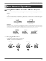
Using Different Nose Cones for Different Purposes
The machine comes with three types of nose cones, one large, one medium, and one small. For engraving general items such as
nameplates, you use the medium-size one already installed in the machine. Use the large- and small-size ones in cases like
following.
Large-size
You use this one when characters are large and the fill width is broad. In the engraving mode, fill operations whose width is
broader than the diameter of the nose cone cannot be performed. Make sure that the nose cone does not become snagged on
differences in levels.
Large
Medium or small
Small-size
In the engraving mode, you can engrave even cylindrical and curved objects. Using the small-size nose cone in such cases can
produce attractive finished results. Note, however, that the greater is the amount of curvature (that is, the more acute is the angle
of the surface), the shallow is the engraving. Also, the flat cutter cannot be used with the small-size nose cone.
Large
Small
Large amount of curvature
Changing the Nose Cone
To change the nose cone, first detach the depth regulator unit.
p. 29 "Detaching the Depth Regulator Unit"
Attaching
Detaching
39
EGX-20 USER'S MANUAL
Using the 3D Cutting Mode
This section introduces some advanced techniques for using the 3D cutting mode more fully. Try them out in situations like the
following.
Performing a special engraving operation
This includes times when you want to do something like performing fill engraving over a width that is broader than the diameter
of the nose cone, or engraving the entire surface of an irregularly shaped (that is, non-rectangular) plate. Note, however, that the
thickness of the plate must be uniform.
Creating a relief with a higher-quality finish
When creating a relief, there may be minute fluctuations in the uniformity of the finished thickness, or there may be slight uncut
areas. You can eliminate such problems.
This requires a preparatory operation called "surfacing."
What Is Surfacing?
Surfacing is an operation that cuts the entire surface of the table to obtain a level finish. However, because you cannot cut the
table directly, the process involves attaching an acrylic panel or the like and cutting the surface of the panel instead. The
precision of the surface produced in this way is sufficient to obtain a uniform cutting-in depth in the 3D cutting mode. You attach
the material to the top of the surfaced acrylic panel.
Requirements for Surfacing
Have the following items available. Also, you use the included Dr. Engrave program.
Plastic panel (acrylic or the like)
Size: 203.2 x 152.4 mm (8 x 6 in.)
Thickness: 2 mm (0.08 in.) or more, up to about 10 to 15 mm (0.4 to 0.6 in.)
Must be flat with no warping
Cutter
Roland DG ZEC-A2320 (flat cutter, blade width 3.175 mm)
Double-sided tape
Must be thin
Performing Surfacing
Perform cutting in the 3D cutting mode. For information on such matters as how to install the cutter and set the origin point,
refer to "4. Creating a Relief (3D Cutting Mode)." Note that the thickness of the material that you can mount is reduced by an
amount equal to the thickness of the attached panel.
It takes about four hours to finish cutting the entire surface of the panel (for acrylic).
40
5. More Advanced Operations
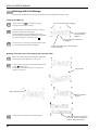
1.
2.
Follow the procedure in "4. Creating a Relief (3D Cutting
Mode)" to detach the depth regulator unit and install the cutter
(ZEC-A2320).
Use the double-sided tape to attach the acrylic panel to the
table securely.
Align the corners of the panel with the holes at the four corners of
the table. Attach the panel securely so that it does not slip or come
loose.
9.
Make the settings for cutting parameters such as [Engraving Area] and [Material] as follows, then click [OK].
[Engraving Area]:
Width 203.2 mm (8 in.), length 152.4 mm (6 in.)
[Material]:
The composition of the attached panel ([Acryl] or the like)
[Z Down Position]:
-1 mm
Table
Acrylic panel
3.
Lower the cutter to a height about 1 mm (0.04 in.) from the
surface of the panel.
Cutter
Acrylic panel
About 1mm
(0.04 in)
4.
Move the cutter to each of the four corners of the panel (A
through D) to determine the corner where the clearance is
the smallest.
If this is difficult to determine, try slipping a stack of several sheets
of paper in the gap between the cutter and the panel. Use the number of sheets of paper that can pass through the gap as an indicator
for determining the amount of clearance.
-1.00
Clearance
* The screens shown are for Windows 95/98/Me.
10. Set the machine's Speed control at its central position and
the Spindle Speed control at the maximum setting.
5.
Move the cutter to the corner that you determined in step 4
to have the smallest clearance, and make the setting for the
height origin point at the surface of the panel.
6.
Move the cutter all the way to the front left of the table and
make the setting for the origin point for the vertical and horizontal dimensions at that location.
7.
Start the included Dr. Engrave program and open the attached "sample1.ded" file.
The sample1.ded file is on the drive where you installed Dr. Engrave, in the [Program Files] - [Dr.Engrave] - [samples] folder.
8.
Speed control
Spindle
Speed control
11. At the Dr. Engrave [File] menu, select [Print], then click [OK].
Surfacing starts.
At the Dr. Engrave [File] menu, select [Print Setup], then
select [EGX-20]. Click [Properties].
41
EGX-20 USER'S MANUAL
6 Optional Parts
Replacement Cutters and Consumable Parts
The following replacement blades and consumable parts are available.
Replacement Cutters
General-purpose (general-purpose cutters suitable for engraving acrylic and plastic plates)
(Blade width)
• ZEC-A2013
0.127 mm
• ZEC-A2025
0.254 mm (* This is the originally included blade.)
• ZEC-A2051
0.508 mm
• ZEC-A2076
0.762 mm
Flat cutter (blades having a wider tip than general-purpose cutters)
(Blade width)
• ZEC-A2150
1.52 mm
• ZEC-A2190
1.91 mm
• ZEC-A2230
2.29 mm
• ZEC-A2320
3.175 mm
Quarter-round types (having a larger tip pocket than general-purpose cutters, and suited to engraving soft material at high speed)
(Blade width)
• ZEC-A2013-QR
0.13 mm
• ZEC-A2025-QR
0.25 mm
Adhesive Sheet
• AS-10
10 sheets
Replacement Parts
42
• ZM-12
Spindle-motor unit (with a belt and a pulley)
* As a general guide, we recommend replacing this after every 1,000 hours.
• ZS-20
Spindle unit
6. Optional Parts
Optional Parts for Scribing
These are optional items for scribing. Use the burnishing attachment and the diamond scraper together as a set.
• ZB-20
• ZDC-A2000
Burnishing attachment
Diamond scraper
To Perform Scribing
Scribing is a form of engraving that involves scraping the workpiece. The spindle is not rotated. This does not perform deep
cutting-in, but it produces an engraving with a distinctive texture and little burring. It is suited for use with light metals such as
aluminum or brass plates.
1. Installation
To perform scribing, use the 3D cutting mode. Remove the depth regulator unit. Also detach the cutter holder and install the
burnishing attachment instead.
The methods for attaching the diamond scraper and setting the origin point are the same as for an ordinary tool. Follow the same
procedure as for use in 3D cutting mode.
2. Program Operation
Program operation is similar to the procedure for creating a nameplate. Use Dr. Engrave.
For the cutting parameters set using the driver, make the following settings at the printer-setting [Properties] page.
[Tool]
1.For [Material], select [Scribing].
2.For [Z Down Position], enter -5 mm, and for [Z Engraving Pitch], enter 5 mm.
[Options]
Select the [Engrave with Spindle OFF] check box to make the setting for performing engraving without rotating the spindle.
43
EGX-20 USER'S MANUAL
7 Appendix
Daily Care and Maintenance
• Use a vacuum cleaner to carefully clean away cutting dust.
• Use a toothbrush or the like to remove cuttings from the adhesive sheet.
• Do not use an air blower or the like to blow away cutting dust. The cuttings may get inside the machine and cause breakdown.
• Use a dry or well wrung-out cloth to wipe clean. Do not use solvents such as thinner or alcohol.
• Lubrication is not required. Improper application of grease or the like may actually lead to breakdown and should not be
attempted.
Functions Using the Switch Panel on the EGX-20
In addition to the usual operations using the switch panel, you can also use the switch panel to carry out operations like the ones
described below.
Carry out the following operations with the power to the EGX-20 switched off and the EGX-20 disconnected from the AC
adapter.
Displaying the Working Time of the Spindle Motor
During normal operation, if the Z-axis light flashes slowly for ten seconds (four or five flashes) when you turn on the power,
it means the spindle motor has been powered up for over 1,000 hours.
The spindle motor is a consumable part. As a general guide, we recommend replacing it after every 1,000 hours.
You can also use the following procedure to check the number of hours that the spindle motor has been powered.
1. While holding down the View button on the switch panel, insert the AC adapter into the EGX-20.
The illumination and flashing of the Z-axis light, Power light, View light, and Origin Set light show how many hours the
unit has been powered up.
2. After you have verified the time, press the View button. This switched off the power.
Z-axis light
Less than
250 hours
Less than
500 hours
Less than
750 hours
Less than
1,000 hours
1,000 hours
or more
●
●
●
●
★Slow flashing
Power light
–
–
–
●
●
View light
–
–
●
●
●
Origin Set light
–
●
●
●
● : Illuminated
●
– : Dark
★ : Flashing
Resetting the Working Time of the Spindle Motor
When you have replaced the spindle motor with a new motor, follow the steps below.
• While holding down the power and View buttons on the switch panel, insert the AC adapter into the EGX-20.
The View light illuminates and the powered time of the spindle motor is reset.
Setting the Origin Point to Its Default Value (the Lower Left Corner)
• While holding down the Origin Set button on the switch panel, insert the AC adapter into the EGX-20.
The Origin Set light illuminates and the origin point is set to its default (at the lower left corner).
Setting the Origin Point at the Center of the Table
• While holding down the center of the movement button on the switch panel, insert the AC adapter into the EGX-20.
The Z-axis light illuminates and the origin point is set at the center of the table.
44
7. Appendix
What to Do If...
The power switch doesn't turn on the power.
• Disconnect the AC adapter from the machine, reconnect it, then turn on the power.
The power switch doesn't turn off the power.
• Disconnect the AC adapter from the machine.
The power light flashes every 0.25 seconds, and the machine operations strangely or not at all.
• Incorrect data has been sent. Check whether an incorrect printer driver has been selected. Also check for faulty cable connections and
the like.
The power light flashes once a second and the machine stops.
• The load is excessive. You can resume operation by pressing the View button, but if operation stops again, make the cutting parameters less demanding, such as by using a slower speed. If the problem occurs frequently, the cutter or the spindle motor may have
reached the end of their service life.
The Z-axis light flashes for ten seconds.
• The usage time of the spindle motor has exceeded 1,000 hours. The spindle motor is a consumable part. As a general guide, we
recommend replacing it after every 1,000 hours.
All the lights flash and the machine doesn't operate.
• Disconnect the AC adapter from the machine, reconnect it, then turn on the power.
The depth gradually changes during engraving.
• This can be caused by large changes in temperature due to a heater or the like. Wait for the temperature to stabilize, then reinstall the
blade.
The depth is uneven or unattractive.
• The installed cutter may be loose. Tighten securely using the hexagonal screwdriver. Also tighten the cutter holder securely. (The
cutter holder is reverse-threaded, so turn counterclockwise to tighten.)
Some portions were not engraved.
• This happens when the nose cone is lifted up by a burr and momentarily loses contact with the material. Adjust the cutting parameters
so that no burrs are formed.
• If some areas are unengraved, try performing cutting a second time. This means performing exactly the same engraving one more
time, without detaching the material. Before you perform engraving the second time, be sure to carefully clean away any cuttings.
The actual depth is completely different from the set depth.
• Is the depth regulator unit installed? Was installation or removal of the depth regulator unit carried out with the power off? When you
turn on the power after installing or removing the depth regulator unit, the machine automatically changes to the Engraving mode or
the 3D Cutting mode.
A screeching sound is heard and engraving takes place at a strange location or is misaligned.
• The machine lost its positioning, possibly because the material became caught on something. Reset the power and redo the operation
from the beginning. The nose cone cannot go beyond differences in level, so go into [Print Setup] and set the cutting area to a suitable
value to prevent movement beyond the edges of the material.
• It is possible that excessive buildup of cuttings has occurred, and some cuttings have gotten inside the machine. Cleaning thoroughly
using a vacuum cleaner or the like. Cleaning should be performed carefully.
• If the problem persists, a breakdown may have occurred. Contact your authorized Roland DG Corp. dealer or service center.
45
EGX-20 USER'S MANUAL
No engraving is performed when data is sent from the computer.
• If the View light is illuminated, it means that operation is paused. Press the View button to release it.
• The origin point is too far toward the back or right side of the table. Set the origin point again.
The spindle motor does not turn.
• In the [Properties] dialog box of the printer setting, on the [Options] page, there is a setting called [Engrave with spindle motor
stopped]. Check this.
• Applying lubrication may lead to buildup of cuttings that then hardens. Clean away using a brush or the like.
• The spindle motor may have reached the end of its service life. The spindle motor is a consumable part. As a general guide, we
recommend replacing it after every 1,000 hours.
Part of the carriage strikes the material while in the 3D Cutting mode.
• The maximum cutting depth when in the 3D Cutting mode is 7 mm. Check whether you are attempting to create a relief larger than
this.
The cutter holder cannot be removed.
• The cutter holder is reverse-threaded. Turn it clockwise to remove it.
The View light is not illuminated when switching the power on.
• Switch off the power to the EGX-20. Rotate the part in the figure counterclockwise a few turns. Switch on the power, and make sure
whether the View light illuminates.
Carriage
Spindle unit
46
Spindle motor
7. Appendix
Specifications
Main Unit Specifications
Table size
220 (W) x 170 (D) mm (8-5/8 (W) x 6-11/16 (D) in.)
Table load weight
Maximum 1 kg (2.2 1b.)
Carriage cutting range
203.2 (X) x 152.4 (Y) x 31.8 (Z) mm (8 (X) x 6 (Y) x 1-1/4 (Z) in.)
Carriage operating speed
X and Y axes: 0.1 to 1 mm/s, 1 to 15 mm/s (0.0039 to 0.59 in./s)
Z axis: 0.1 to 1 mm/s, 1 to 6 mm/s (0.0039 to 0.23 in./s)
Cutting-depth control
AST (Active Surface Tracking) system
Cuttable depth
3D Cutting mode: 0.05 to 7 mm (0.002 to 0.27 in.)
Engraving mode: 0.05 to 1 mm (0.002 to 0.039 in.)
Cuttable material
Composition: Resin (acrylic, modeling wax, ABS, polyacetal, polycarbonate, styrenefoam,
etc.), wood, and plaster
Maximum thickness: 30 mm (1-1/8 in.)
Resolution
0.01 mm/step (0.00039 in./step)
Spindle motor
12 W (DC motor)
Spindle rotating speed
4,000 to 15,000 rpm
Overload detection feature
Yes
Cutter diameter
3.175 mm (1/8 in.)
Interface
Parallel (compliant with IEEE 1284)
Buttons and controls
Movement button (joystick type), Power button, View button, Origin Set button, Speed
control, and Spindle Speed control
Indicators
Z-axis light, Power light, View light, and Origin Set light
Power supply
Dedicated AC adapter
Input: AC 100 to 240 V ±10%, 50/60 Hz
Output: DC 19 V, 2.1 A
Power consumption
Maximum during operation: 0.6 A at 100 V, 0.27 A at 240 V
Operating noise level
Standby: Less than 45 dB (A)
No-load operation: Less than 70 dB (A) (according to ISO 7779)
External dimensions
515.2 (W) x 368.3 (D) x 270.6 (H) mm (20-5/16 (W) x 14-1/2 (D) x 10-5/8 (H) in.)
Machine weight
10.9 kg (24 1b.)
Packed dimensions
673 (W) x 518 (D) x 412 (H) mm (26-1/2 (W) x 20-3/8 (D) x16-1/4 (H) in.)
Packed weight
15.5 kg (34.2 1b.)
Operating environment
Temperature: 5 to 40 ºC (41 to 104 ºF)
Relative humidity: 35 to 80% (no condensation)
Included items
AC adapter, power cord, cutter, cutter holder, nose cones (large, medium and small), adhesive
sheet, test-use plate material, hexagonal screwdriver, hexagonal wrenches (large and small),
Roland Software Package, User's Manual
Parallel Interface Specifications
Rating
Compliant with IEEE 1284: Nibble mode
Input signals
STROBE (1 bit), DATA (8 bits), SLCT IN, AUTO FEED, and INIT
Output signals
BUSY (1 bit), ACK (1 bit), FAULT, SLCT, and PERROR
Input/output signal level
TTL level
Transmission method
Asynchronous
47
EGX-20 USER'S MANUAL
48
Please read this agreement carefully before opening the sealed
package or the sealed disk package
Opening the sealed package or sealed disk package implies your acceptance of the terms and conditions of this agreement.
Roland License Agreement
Roland DG Corporation ("Roland") grants you a non-assignable and non-exclusive right to use the COMPUTER
PROGRAMS in this package ("Software") under this agreement with the following terms and conditions.
1. Coming into Force
This agreement comes into force when you purchase and open the sealed package
or sealed disk package.
The effective date of this agreement is the date when you open the sealed package
or sealed disk package.
2. Property
Copyright and property of this Software, logo, name, manual and all literature
for this Software belong to Roland and its licenser.
The followings are prohibited :
(1) Unauthorized copying the Software or any of its support file, program module
or literature.
(2) Reverse engineering, disassembling, decompiling or any other attempt to
discover the source code of the Software.
3. Bounds of License
Roland does not grant you to sub-license, rent, assign or transfer the right granted
under this agreement nor the Software itself (including the accompanying items)
to any third party.
You may not provide use of the Software through time-sharing service and/or
network system to any third party who is not individually licensed to use this
Software.
You may use the Software by one person with using a single computer in which
the Software is installed.
4. Reproduction
You may make one copy of the Software only for back-up purpose. The property
of the copied Software belongs to Roland.
You may install the Software into the hard disk of a single computer.
5. Cancellation
Roland retains the right to terminate this agreement without notice immediately
when any of followings occurs :
(1) When you violate any article of this agreement.
(2) When you make any serious breach of faith regarding this agreement.
6. Limitations on Liability
Roland may change the specifications of this Software or its material without
notice.
Roland shall not be liable for any damage that may caused by the use of the
Software or by exercise of the right licensed by this agreement.
7. Governing Law
This agreement is governed by the laws of Japan, and the parties shall submit to
the exclusive jurisdiction of the Japanese Court.
R3-030620