1
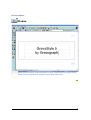
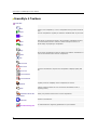
GravoStyle 5 LASER Option
User Manual
Table Of Contents
G5 LASER OPTION ........................................................................................................................... 1
Window............................................................................................................................. 1
GravoStyle 5 Menus ..................................................................................................................... 2
GravoStyle 5 Toolbars.................................................................................................................. 4
USING A TARGET MACHINE ............................................................................................................... 7
Installing a new target machine .................................................................................................. 7
Adding a target machine to Windows .......................................................................................... 8
Setting the properties of a target machine in Windows ..............................................................10
MATERIAL MODE ............................................................................................................................13
Entering the dimensions and margins.........................................................................................13
Engraving properties .....................................................................................................................15
Defining the composition’s engraving properties ..........................................................................15
Setting the composition’s origin ................................................................................................16
Designating the composition’s orientation ...................................................................................17
Setting the parameters for engraving on a cylinder ......................................................................18
Checking the composition’s configuration ..................................................................................19
ENGRAVE THE COMPOSITION ...........................................................................................................21
Engraving the composition with an L-Solution machine...................................................21
Arranging objects .......................................................................................................................22
Engraving path ..............................................................................................................................23
Assigning an engraving path to an object ..............................................................................23
Laser engraving properties ............................................................................................................25
Defining the engraving properties with an L-Solution machine...................................................25
Defining the general laser engraving parameters .........................................................................26
Defining the laser path engraving parameters .............................................................................27
Defining the general laser engraving options ...............................................................................29
Processing bitmap images for laser engraving .............................................................................30
Producing a stamp..................................................................................................................31
Transfer for engraving ...................................................................................................................32
Transferring the composition to the L-Solution machine ...........................................................32
Selecting the engraving paths to be transferred...........................................................................33
Configuring transfer to the machine...........................................................................................34
INDEX ..........................................................................................................................................35
i
G5 Laser Option
Window
When many document or program windows are open, quickly locate GravoStyle window
thanks to the Gravograph logo displayed in the bottom right corner.
1
GravoStyle 5 LASER Option User Manual
GravoStyle 5 Menus
Click a menu for more information.
?Help
Contents
Search
Use Help
Consulting on-line Help
About
Commanding and integrating a program option or
level
File
New
Open
Save
Save as
Creating a composition
Opening a .gnh file
Saving while working
Saving a composition
Open a model
Creating a composition from a template
Save a model
Saving a composition as a template
Find
Information
Finding a .gnh file
Information about the current composition
Import
Export
Importing objects in composition
Exporting objects to an external program
Insert object
Retrieving a bitmap image saved with vectorial
contours
Vectorize / Vectorize Parameters
Scan / Select scanner
Vectorizing an image
Digitizing an image
Print
Print preview
Print parameters
Printing the composition
Recent files
List of the last four files opened
Exit
Close the window and exit the program
Edit
Undo
Redo
2
To cancel/restore a procedure
Cut
Copy
Paste
Delete
Placing objects
Select all
Selecting objects
Pointer position
Snap mode
View object
Mouse use
Work area
Clear Undo Memory
Deleting the saved cancellations
Options
Customize the program
G5 Laser Option
View
Zoom
Last Zoom
Max Zoom
Zoom material
Zoom selection
Zoom tools
Redraw
Quick Redraw
Redisplaying the composition
Wire direction
Viewing draw direction
Graphic mode
Arrow direction
Display mode for engraving paths
Viewing draw direction
Modify
Text
Using the Advanced Text functions (non-horizontal
text, font editor, etc.)
Shapes
Drawing geometric shapes
Align
Aligning objects
Effects
Applying effects to objects
Duplicate
Duplicating an object
Transform
Transforming an object
Tasks
Creating professional objects
Material
Configuring the composition
Guide lines
Managing guide lines
Symbols
Placing objects from program library
PhotoStyle
Processing a bitmap image using PhotoStyle
Bitmap Editor
Retouching a bitmap image
Wysiwyre
Displaying 2D render on material
Machining
Setup machines
To add a target machine
Laser
To open the L-Solution dialog box
3
GravoStyle 5 LASER Option User Manual
GravoStyle 5 Toolbars
Main Bar
New
Open
Create a new composition, or use a composition that you have saved as
a file.
Save the composition regularly to avoid the accidental loss of your work.
Save
Undo
Each action you perform is saved in the program’s Undo/Redo memory.
You can therefore cancel or restore a series of steps to return to a
specific stage of preparing a composition.
Redo
Copy
Paste
Call up these commands to insert an object from another composition or
from an external document into the composition.
Cut
Zoom area
Last zoom
Max zoom
Use these commands to improve the composition’s display quality and
size.
Zoom material
Zoom selection
Regularly force the redisplay of the composition on-screen.
Redraw
Print
Comments about the
composition
Produce a paper printout for a pre-engraving presentation (test or
engraving check).
Attach your personal notes to the current composition.
Contact us via Internet.
Web links
Set and transfer the engraving parameters to your machine.
L-Solution dialog box
4
G5 Laser Option
Toolbox
Working modes
Creating objects
Handling objects
Material mode
Advanced Text
Group
Selection mode
Symbols
Ungroup
Text mode
Tasks
Align
Drawing mode
Transform
Point mode
Measure
Duplicate
Effects
Engraving
Wysiwyre
Using a bitmap image Engraving environment
PhotoStyle
for IS machines
Engraving quotation
Bitmap Editor
Scanner
for L-Solution machines
Assign a laser path
Vectorize
for IS machines
Functionality available in Discovery level
Functionality available in Graphic level
5
Using a target machine
Installing a new target machine
Open the Machines dialog box: click the Setup machines command in the Engraving menu.
Close When you close the Machines dialog box, a message will ask if the default target machine’s dimension
area become the default dimensions.
Yes Click to assign these dimensions to each blank composition.
Creating a target machine
A.
Click opposite the Add a machine icon.
The new target machine is featured in
the list of the machines installed in the
Machines dialog box. It is automatically
designated as the target machine by
default.
B.
Click opposite the type of your machine.
C.
Right-click the machine model in the list of available
machines.
D.
Click the Add this machine command in the contextual
menu.
E.
Double-click on Add to Windows in the Configure output
dialog box and add the target machine to Windows: the
target machine appears in the List of installed printers.
If you ticked option L-Solution
Printer at the end of the setup:
E.
Click L-Solution in the List of
installed printers of the Configure
output dialog box.
Click. Continue the installation.
Click.
F.
Set your machine's properties in the L-Solution
Installation dialog box:
Click the Bridge fitted on your machine.
Click the Laser power (10 to 60 Watts, see the serial
plate at the back of your machine).
Click.
G.
Type the Name of the target machine in the Machine
Properties dialog box.
Click.
Designate by default
1.
2.
Properties
Delete
1.
Right-click a target machine.
Click the Set as default command in the contextual
menu: the default target machine becomes active in the
Material dialog box.
Right-click a target machine.
2.
Click the Properties command in the contextual menu.
3.
Configure the target machine in the Machine Properties
dialog box.
1.
2.
Right-click a target machine.
Click the Delete command in the contextual menu.
7
GravoStyle 5 LASER Option User Manual
Adding a target machine to Windows
Install the target machine as a printer (the order of the procedures varies depending on the Windows system
install on your computer).
The installed machine features in the
output dialog box.
1.
2.
Printers folder and its name is displayed in the Configure
Install the target machine. The Add printer Wizard opens when you double-click Add to Windows in
the Configure output dialog box.
Next> Click in the Add printer Wizard.
3.
Click
Local printer (
Next> Click.
4.
Click the Port which the cable linking the computer and the machine is plugged into. Next> Click.
LPT
unclicked Plug & Play box).
if the connection is hooked up using a Gravograph parallel cable plugged into the machine’s parallel
port and into one of the computer’s LPT ports.
COM if the connection is hooked up using an adapted Gravograph serial cable plugged into the machine’s
serial port and into one of the computer’s COM ports.
Configure the serial link.
FILE if the engraving is saved in the form of a file for subsequent transfer to your machine.
5.
Select the Windows driver used to communicate with the target machine.
You are adding a target machine
for the first time.
You have a new version of the LSolution driver.
Each time you receive a new
version of the L-Solution driver
on the GravoStyle CD-ROM,
consider updating the driver for
each existing L-Solution target
machine.
a.
Have Disk Click in the Add printer Wizard.
b.
Browse Click in the Install from Disk dialog box.
c.
Place the GravoStyle installation disk in your computer’s
CD-ROM drive.
d.
In Windows, double-click the
LaserStyle drive
Driver L-Solution folder
glaser.inf file
e.
Click in the Install from Disk dialog box.
f.
Click the L-Solution printers driver.
Next> Click.
g.
If you are installing a new version of the driver, click
Replace the existing driver.
Next> Click.
You have already added a target
machine referenced by the LSolution driver.
a.
Click the Gravograph-New Hermes Manufacturer,
and then on the L-Solution driver.
Next> Click.
b. Click
Keep the existing driver.
Next> Click.
8
Using a target machine
6.
Type the machine’s name under Printer name. Next> Click.
7.
Click No to avoid designating this machine as the default printer.
Next> Click.
8.
Click
Do not share this printer.
Next> Click.
9.
Click
No to avoid printing the test page.
Finish Click.
10. Continue installing the target machine.
9
GravoStyle 5 LASER Option User Manual
Setting the properties of a target machine in Windows
1.
Select the target machine to be configured in the
L-Solution dialog box.
2.
Spooler Click: the print manager window for the machine opens.
3.
Click the Properties command in the Printer menu.
4.
Modify the properties of your choice in the target machine's Properties dialog box.
5.
Close the printer’s Properties dialog box.
6.
Close the print manager window.
To bring up the Windows contextual help, click this box, then a zone in the dialog box.
Configuring the serial link
a.
Synchronize the serial link parameters
between the computer and the engraving
b.
machine each time you
• add a target machine using a COM
c.
port.
• select this target machine to engrave the d.
composition.
If the serial parameters for the
computer and the engraving
machine are different, errors may
occur during transfer, which will
alter the execution of the
engraving.
e.
f.
In the target machine’s Properties dialog box, click the
Ports tab.
In the list of ports, click the COM port which the cable
linking the computer and the machine is plugged into.
Configure Port Click.
In the COM Properties dialog box, click the Parameters
tab.
Key in the serial parameters for the machine (see the
Gravograph user manual).
Click.
Designate the type of data transferred
to the machine
Windows 98 a.
b.
c.
Windows 2000 a.
b.
c.
10
In the Properties dialog box, click the Details tab.
Spool Settings Click.
Click the RAW default data type.
In the Properties dialog box, click the Advanced tab.
Print Processor Click.
Click the RAW default data type.
Using a target machine
Updating the L-Solution driver
a.
New Driver Click in the target machine's Properties dialog
box.
b.
Have disk Click in the Add printer Wizard.
c.
Browse Click in the Install from Disk dialog box.
d.
Place the GravoStyle installation disk in your computer’s CDROM drive.
e.
In Windows, double-click the
LaserStyle drive
Driver L-Solution folder
glaser.inf file
f.
g.
h.
i.
j.
Click in the Install from Disk dialog box.
Click the L-Solution printers driver.
Next> Click.
Finish Click.
Yes Click if a message asks whether you want to continue
installing following a problem.
Click in the target machine’s Properties dialog box.
11
Material mode
Entering the dimensions and margins
The exterior frame delimits the composition’s surface area, in
accordance with its dimensions.
The dotted frame represents the margins that separate the zone
reserved for the text from the border designed to immobilize the
plate.
You can customize the color of the composition and the margins.
If the new dimensions/margins decrease the length of
a line of text in relation to that of the text typed in, the
text will automatically be compressed.
Click the Dimensions and margins tab in the
Material dialog box.
Material's dimensions
If one of the composition’s dimensions exceeds the height of the
engraving area, the other has to be less than the engraving
area’s length (limit of the tool’s movement on the X axis).
A message will ask you to confirm dimensions selected that are
greater than the engraving area’s dimensions.
Yes Click if you are configuring a composition on a cylinder.
1.
Key in a length no greater than the length of the engraving area.
2.
Key in a height no greater than the length of the engraving area.
3.
Key in a thickness no greater than the depth of the engraving
area.
13
GravoStyle 5 LASER Option User Manual
Composition’s margins
If you place the text in manual mode, all the margins will be
cleared.
Proportional margins Click box
Margins auto-correction.
The left and right margins are each equal to 15% of the composition’s
length.
The top and bottom margins are each equal to 10% of the composition’s
height.
Margins equal to the left 1.
margin
2.
Different Margins 1.
Click box
Same margins.
Key in the left margin.
Check that no boxes are clicked.
2. Key in each margin.
The distance between the left and right margins has to be between 0.01 mm
and the length of the composition.
The distance between the top and bottom margins has to be between 0.01
mm and the height of the composition.
Customizing the standard
dimensions and margins
The default dimensions equal
• the dimensions of the default
target machine’s area.
• 1,000 x 1,000 mm, if you
have not created a target
machine.
14
1.
Click the Material tab in the Options dialog box.
2.
Key in the dimensions and margins as described above.
Click in the main toolbar to create a blank composition from latest
default dimensions and margins.
Material mode
Engraving properties
Defining the composition’s engraving properties
1.
Click the Engraving properties tab in the Material dialog box.
2.
Set the engraving properties below.
3.
Check that the composition’s configuration is correct.
Designate the active target machine which will actually engrave the current
composition. Its engraving area delimits the composition’s maximum surface area.
Cancel Click if there isn’t one. Add this target machine, and then designate it in the
Material dialog box.
Designate as default target machine
Click box
Set as default machine if you perform engraving regularly using the
active target machine.
The machine selected automatically becomes the default target machine in the
Machines dialog box.
When you click to validate your composition’s configuration, a message will ask if
the default target machine’s area has to delimit the maximum surface area for each
blank composition.
Yes The dimensions of the engraving area will become the default dimensions in the
Options dialog box.
Designate the engraving orientation
Set the engraving origin
center or
normal or
rotated.
upper left-hand corner.
If needed, set the parameters for engraving on cylinder.
15
GravoStyle 5 LASER Option User Manual
Setting the composition’s origin
1.
Click the Engraving properties tab in the Material dialog box.
2.
Select the origin depending on the composition’s position in the engraving area. Click a
fixed origin (center or left) or on a floating origin (center or left).
The composition’s origin will become floating when it does not match any fixed origins. This is
the case when:
• The plate’s footprint does not make it possible to fix it at the center or in the left-hand corner
of the engraving area.
• The composition’s position on the plate offsets its origin in relation to the center or the lefthand corner of the engraving area.
Machine center
The center of the composition matches the center of the engraving area. This fixed origin is
recommended for engraving on a self-centering vice. This accessory makes it possible to
center the plate in the engraving area.
Machine’s left corner
The upper left-hand corner of the composition matches the upper left-hand corner of the
engraving area.
Floating center
Key in the XY coordinates for the center of the composition in the engraving area (the
default value is zero).
Floating left corner
Key in the XY coordinates for the upper-left hand corner of the composition. Default
settings:
• The X coordinate equals half of the length of the engraving area.
• The Y coordinate equals half of the height of the engraving area.
You can only select a floating origin if the composition’s surface area is less than the engraving
area.
Check that the floating origin’s position does not place the composition outside the engraving
area. If this is detected during transfer for engraving, a message displays asking you to correct
the floating origin’s XY coordinates.
Correct floating origin
The upper left-hand corner of the composition (red
frame) remains within the engraving area (gray surface).
The plate (green surface) is fixed onto the upper lefthand corner of the engraving area.
16
Incorrect floating origin
The upper left-hand corner of the composition is
outside the engraving area.
Only the portion of the composition inside the
engraving area will be engraved onto the plate.
Material mode
Designating the composition’s orientation
1.
2.
Click the Engraving properties tab in the Material dialog box.
Click the orientation suited to the material being engraved and the composition's dimensions.
Any orientation is possible, provided each dimension is less than or equal to the height of the engraving area.
The other dimension will not exceed the height of the engraving area.
Normal if the length of the composition
exceeds the height of the engraving area.
90°-rotation if the height of the
composition exceeds the height of the
engraving area.
Upside to directly
engrave the
material's surface.
Reversed to
engrave materials
that have a
transparent upper
layer (Gravoglas 2).
17
GravoStyle 5 LASER Option User Manual
Setting the parameters for engraving on a cylinder
Consult the Gravograph manuals enclosed with your machine and the cylinder engraving
accessory.
Set the dimensions and margins.
If one of the composition’s dimensions exceeds the
height of the engraving area, a message will ask you to
confirm dimensions selected that are greater than the
engraving area’s dimensions.
Yes Click to configuring the composition on a cylinder.
1.
Click the Engraving properties tab in the Material dialog
box.
2.
Set the composition’s floating origin (default setting:
center). Key in only its X coordinate in the engraving area.
The Y coordinate, which equals half the height of the
engraving area, remains fixed.
3.
Click to activate the cylinder
engraving.
4.
Key in the diameter of the cylinder.
Cylinder engraving is automatically activated in the L-Solution dialog box
18
Material mode
Checking the composition’s configuration
1.
2.
3.
Configure the composition.
Click the Engraving properties tab in the Material dialog box.
Note the comments in the Info zone and act accordingly:
Your configuration is correct: the composition (red frame) remains in the
engraving area (gray surface).
The composition is physically outside the engraving area. However, its
surface area does not exceed the engraving area.
Correct the composition's orientation or origin.
Configure the composition
• for cylinder, if your machine is equipped with this accessory.
It is impossible to engrave: the composition’s surface area exceeds the
engraving area in both length and height.
Correct the composition's dimensions.
Designate a target machine that offers a larger engraving area.
Maximum number of plates If you are producing a Matrix series, this value indicates the total number of
elementary plates that you can engrave in the engraving area according to
the standard plate’s configuration.
19
Engrave the composition
Engraving the composition with an L-Solution
machine
Arranging objects on-screen
Change the order in which objects are displayed to
manage superimposed engraving laser paths.
Assigning a laser path to an object
Decide what procedure the laser beam will follow in
order to engrave the object.
Defining the laser engraving properties
Set the parameters and options involved in the
physical execution of the engraving.
Engraving on a cylinder
The Cylinder Engraving mode allows a composition
intended for engraving on a cylinder to be configured.
Wysiwyre 2D render
Simulate the engraving of the composition in the
material of your choice.
Transferring for engraving
Transfer the composition data from the computer to
the engraving machine.
21
GravoStyle 5 LASER Option User Manual
Arranging objects
To manage superimposed objects, you can change the order in which they are displayed in the composition.
The portions of the objects covered by other objects are ignored during engraving.
Correctly superimposed: text in front of the
shape
Incorrectly superimposed: text concealed by the
shape
If you paste or move the selection, it is displayed in front of all the placed objects.
1.
Select some objects.
2.
Click the command in the Align palette or in the Modify/Order menu.
Type the hotkey.
Front
To place the selection in the foreground
Behind
To place the selection in the background
Forward
To move the selection forward
Backward
To move the selection backward
22
Engrave the composition
Engraving path
Assigning an engraving path to an object
Assigning a tool path
1.
Open the Laser Colors palette:
the toolbox.
click in
Each color corresponds to a path.
Click to use more or fewer colors (4
minimum).
Defining a tool path properties
2.
Define the properties of each path.
3.
Display engraving paths.
4.
Group contours by engraving surfaces.
5.
Select an object or select text.
6.
Double-click a color in the Machining tools
palette. Laser Colors palette.
7.
Repeat steps 4 and 5 for each object to be
engraved.
a.
Click the type of path in the Laser Colors
palette.
b.
Define the marking properties.
Save these properties.
Displaying engraving paths
Type the hotkey or click the command in the View
menu:
Graphic mode to display the
surfaces and contours according to the properties
of the path that is assigned to it (color, fill, line
with thickness, vectors).
23
GravoStyle 5 LASER Option User Manual
Defining the properties of a laser path
Click the type of the laser path and set its properties in the Laser Colors palette.
Raster
The laser beam engraves by sweeping (rectilinear passes).
Click the Raster properties:
Fill
The laser beam sweeps the object’s surface.
Raster Fill is the default path, except for the orange path.
Line
The laser beam sweeps the object’s contours according to the thickness entered.
Key in a Thickness that is greater than 0.1 mm (width of the laser beam).
Fill
Line
The laser beam sweeps the object’s surface and contours according to the thickness
entered.
Key in a Thickness that is greater than 0.1 mm (width of the laser beam).
Fill
Line
An object with an undefined path is displayed using a broken gray line and is not
engraved.
Vectors
The laser beam engraves by following a path centered on the object’s
contours.
Select this path for Cutting or precutting.
The default setting for the orange path is in vectors.
Precutting
The object is displayed using dotted lines.
24
Engrave the composition
Laser engraving properties
Defining the engraving properties with an L-Solution machine
1.
Open the L-Solution dialog box:
Type the hotkey.
Click in the main toolbar.
Click the Marking command in the Engraving menu.
2.
Define the properties involved in the engraving to be executed. You can
Define the general parameters
Define the laser path parameters
Define the general options
Process a bitmap image
Produce a stamp
Click to validate the new properties.
Run Click to transfer the composition to the machine.
25
GravoStyle 5 LASER Option User Manual
Defining the general laser engraving parameters
Open the L-Solution dialog box.
Material Presets
Create a preset to activate the properties specific to
engraving on a specific material.
1.
Set all the engraving properties in the L-Solution
dialog box.
2.
Type the name of the profile.
3.
Click to add the profile.
Click in the Presets list to select a preset (default
setting: Driver).
Click to delete the profile selected.
Select a resolution
DpiX falling between 50 and 1,200 DPI.
Machine resolution
This parameter sets the engraving precision in DPI.
In low resolution (50 to 400 DPI), you will obtain
quick and clean surface engraving.
In high resolution (over 500 DPI), you will obtain
in-depth engraving that is fine and slower.
Origin
These coordinates locate the origin of the composition
in the engraving area. The default setting is for them
to match the top left-hand corner of the engraving
area (Origin 0,0).
DpiY, which by default equals DpiX.
To increase the engraving speed in high resolution,
click box
Fast.
1.
Click to select an origin different from the
one chosen in the Material dialog box.
2.
If you have chosen a floating origin, enter its
coordinates
X, distance from the origin to point 0 on the X
axis.
Y, distance from the origin to point 0 on the Y
axis.
The Width and Height entered in the Material dialog
box are displayed as an indication.
Plate size
26
If a dimension exceeds the engraving area, its value
will be displayed in red.
Engrave the composition
Defining the laser path engraving parameters
For each laser path, set the engraving parameters in the paths table in the L-Solution dialog box.
The parameters of the path defined in the Laser colors palette are entered in this table.
Set these parameters in accordance with the technical characteristics of your L-Solution
machine. Refer to the Gravograph manual enclosed with the machine.
Key in a value between 0 and 100%.
Power expressed in % of the source
This parameter defines a power level proportional to
that of the laser source.
Key in a number between 1 and 9.
Speed expressed in % of the maximum
speed
This parameter defines the speed of the system for
moving the machine proportional to its maximum
speed.
Key in a number between 1 and 9.
Number of passes for cutting or filling
A pass is the equivalent of one passage of the laser
for engraving objects. Several passes may be required
to gradually reach a given depth (engraving on fragile
material).
Refocusing
1.
This parameter defines the material's vertical
displacement to correct the autofocus. Specify this
descent or ascent according to the desired engraving
depth.
2.
3.
Click to activate the refocusing.
Enter a negative or positive distance.
Click to the left or right of the value to release the
autofocus
before or
after engraving.
27
GravoStyle 5 LASER Option User Manual
1.
Air assistance
This flow of air directed onto the laser beam is used to
put out flames produced by engraving on certain
materials.
2.
Check that the air assistance device mounted on
your machine is connected to a compressor (see
the "Installation" and "Air Assistance Device
Requirements" chapters in the L-Solution Machine
user manual).
Click to activate air assistance.
The path type displays:
Marking mode
None
Raster (active default setting for filling and line
with thickness)
Vector (active default setting for cutting)
Point (active default setting for precutting)
28
Undefined path: the object will not be engraved.
Sweeping the surfaces and contours using a width
greater than 0.1mm
Vectorization of contours
Vectorization of dotted line contours
Engrave the composition
Defining the general laser engraving options
Open the L-Solution dialog box.
Click to select a different orientation from the one
chosen in the Material dialog box.
Engraving orientation
Processing a bitmap image
Colors reduction mode
Refocusing
Click to activate the refocusing and configure
this correction on the autofocus.
Suction
1.
Click to activate suction.
Air filtering must always be active so that the smoke
produced during engraving can be removed.
2.
Engraving on a flat surface or Engraving
on a cylinder
Key in the time delay in seconds between
• the start of engraving and starting up suction.
• the end of engraving and shutting down suction.
1.
Click to activate engraving on a cylinder.
Engraving on a cylinder is automatically activated if
you have defined the cylinder engraving parameters in 2.
the Material dialog box.
Key in the diameter of the cylindrical part
to be engraved (max. of 230mm).
Z up position
1.
This parameter, which is measured from the autofocus 2.
point, defines the distance over which the material is
lowered to avoid coming into contact with the focus
carriage during its horizontal movements.
Producing a stamp
Click to activate the clearance.
Enter a movement with a minimum value equal to
the material’s highest relief level.
1.
Click to activate the function.
2.
Click to generate the stamp shape.
Click to activate the engraving properties adapted to
wood laser marking.
Wood preset
29
GravoStyle 5 LASER Option User Manual
Processing bitmap images for laser engraving
This option allows the colors in a bitmap image (photos, drawings, plans) to be corrected to produce the object
to be engraved. Depending on its color, each pixel or point in the image on-screen is converted:
• into a pixel in a shade of gray to black to be engraved (each shade of gray is proportional in relation to
black).
• into a white, unengraved pixel.
1.
2.
3.
Open the L-Solution dialog box.
Click to open the Bitmap dialog box.
Apply the necessary settings:
Brightness
Key in a percentage between 0 and 100% to darken or lighten the image.
Colors correction mode
8-shades Grayscale
Click if the number of colors in the image is less than 8. Each color corresponds to a
level of gray.
Automatic Grayscale
This recommended mode converts the image colors into an equal number of grays.
Halftone
Click to simulate each color using various black and white geometric patterns.
Negative
Depending on the material used, click to convert the final image as a negative.
By reversing the color of points, this command allows a two-layered material with a
light surface and a dark background (for example, Gravoglas white on black) to be
engraved.
30
Engrave the composition
Producing a stamp Option
This option allows stamps to be created for rubber stamps and badges.
Key in the actual dimensions of the stamp as the dimensions of the composition.
1.
2.
Place the objects in the stamp:
a.
Create text objects or curve
objects.
b.
Convert the text to curves.
c.
Group the objects.
Draw the shape representing the cut
contour. This closed contour must
contain all the stamp's objects.
You can create the cut
contour using offset around
the grouped objects.
3.
Draw the shape that represents the
mount of the stamp. This closed
contour must contain the cut contour.
4.
Click in the L-Solution dialog
box.
5.
Click to open the Stamp
dialog box.
6.
Adjust the stamp profile (examples):
Slide the inflexion point in the
preview.
Key in the profile parameters:
• distance from the inflexion point to
the profile start
• profile length
• percentage of the power set for the
black color, that places the inflexion
point at a given engraving depth
7.
Click.
31
GravoStyle 5 LASER Option User Manual
Transfer for engraving
Transferring the composition to the L-Solution machine
Before making the transfer, check that:
• the computer and your machine are correctly connected.
• your machine is powered up.
• your machine is not in the process of making an engraving.
If you have not installed your machine, follow the installation procedure and advice provided in
the Gravograph manual enclosed.
1.
Select the objects to be engraved (all by default).
2.
Open the L-Solution dialog box.
3.
Designate the active target machine; choose the machine that is actually going to engrave
the current composition.
If there is none, add this target machine.
4.
Select paths to be transferred.
5.
Configure the transfer.
6.
Define the properties for laser engraving.
7.
Run Click: the progression bar indicates the percentage of data transferred.
To stop the transfer
8.
9.
On the engraving machine, execute the pre-engraving settings (consult the Gravograph manual for your
machine).
Run the engraving from your machine’s control panel.
The order of creation and selection of the paths determines the engraving order. In terms of
engraving, closed contours are given priority over open contours.
Any modification made to the composition will only apply to the engraving following a new
transfer that deletes the previous one.
32
Engrave the composition
Selecting the engraving paths to be transferred
1.
Click in the L-Solution dialog box: the Layers selection dialog box displays the list of
layers containing the objects selected.
2.
Select the paths to be engraved (all by default): key
Layer.
All Click to select all the paths.
None Click to deselect all the paths.
3.
If you select at least two layers, key in the Engraving delay between two layers (default setting: 5
seconds).
4.
depressed, click to deselect or select a
Click.
33
GravoStyle 5 LASER Option User Manual
Configuring transfer to the machine
These options determine the conditions under which transfer of the composition takes place once you have
clicked Run in the L-Solution dialog box.
Transfer mode
Click the mode you want.
File: You will save the engraving file in the DRAWS so it can
subsequently be transferred to a machine.
Designating another folder
a.
b.
c.
Change Click. The Find File dialog box will open.
Select another folder in Windows Explorer.
Click.
Port: you will send the composition to the active target machine.
Grouping paths by transfer
file
1.
2.
Collate Click.
Click the box for the type of grouping:
By layer to transfer to a distinct file the paths in each layer.
All layers are transferred to a single file.
3.
Click.
Managing transfer files
1.
If you have carried out several
consecutive transfers, you can
define their order of engraving.
2.
Right-click an engraving file.
3.
In the contextual menu, click
• Suspend printing to temporarily interrupt transfer to the machine.
• Cancel printing to cancel the transfer.
34
Spooler Open the Windows manager window for the target machine.
Index
A
M
Align ......................................................... 22
Material ........................... 13, 15, 16, 17, 18, 19
C
P
Composition ............................................... 21
G
Program
preferences .............................................. 13
GravoStyle 5.......................................... 1, 2, 4
S
L
Stamps ...................................................... 31
Laser engraving 1, 2, 4, 23, 24, 25, 26, 27, 29, 30,
31, 32, 33, 34
T
Target machine............................... 7, 8, 10, 15
Tool engraving........................21, 23, 32, 33, 34
35