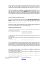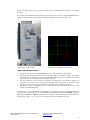
1
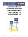
Instruction Manual Remote PC Terminals CHALLENGER 15i-2 CHALLENGER 18i CHALLENGER 22i Manual CHALLENGER Terminal 15i 18i 22i Rev 6d en GEC17500102 Gecma Components electronic GmbH [email protected] +49 2237 6996 0 1 Foreword Attention! Please read this instruction manual and the associated EC Type Examination Certificate carefully before starting to assemble, connect, install and commission this device! The CHALLENGER 15i-2, the CHALLENGER 18i and the CHALLENGER 22i, along with the associated PSU14i/6/543 power supply unit for the CHALLENGER 15i-2 and the PSU14i/8/543 power supply unit for the CHALLENGER 18i and CHALLENGER 22i may only be installed or removed by qualified personnel. Such personnel shall have undergone training, which included instruction on installation practices relevant to hazardous area equipment, the relevant rules and regulations, and on the general principles of area classification. This may include reference to the IEC code of practice IEC 60079-14. The CHALLENGER KB-2S, KMU-2S and MTD-2S, and the KB-2-BCBN*, KMU-2-BCBN*, MTD2-BCBN*, BCBN1i and 15i-FMO, are not currently in production and there are no plans for these to be produced in the foreseeable future; consequently, these units are not mentioned or detailed in this instruction manual. The EC Type Examination Certificate (see page 4) should be fully adhered to. If you have any questions or suggestions, please contact: GeCma Components GmbH Heisenbergstraße 26 – 40 D-50169 Kerpen Tel.: +49 (0)22 37 / 69 96 0 Fax: +49 (0)22 37 / 69 96 99 mailto:[email protected] http://www.gecma.com Technical Developments The manufacturer reserves the right to modify technical data in line with technical developments without notice. Trademarks used: AT, IBM and PS/2 are registered trademarks of the International Business Machines Corporation. Microsoft, Windows and Windows NT are registered trademarks of the Microsoft Corporation. If any other trademarks are used in the text or shown in pictures within this manual, they are herewith acknowledged as the trademarks of the respective owners and are considered to be protected. Manual CHALLENGER Terminal 15i 18i 22i Rev 6d en GEC17500102 Gecma Components electronic GmbH [email protected] +49 2237 6996 0 2 Contents Regulations and general information: Foreword ................................................................................................................................................................ 2 Contents ................................................................................................................................................................. 3 Regulations relating to general operational safety ............................................................................................... 4 Safety regulations .................................................................................................................................................. 5 Introduction ............................................................................................................................................................. 6 Fields of application ............................................................................................................................................... 8 Operating principle ................................................................................................................................................. 8 Design of the various components: Design of the CHALLENGER 15i-2/18i/22i-FMO display module ...................................................................... 9 Design of the CHALLENGER KB/KB-2D/KMU/KMU-2D/MTD/MTD-2D keyboard ......................................... 11 Design of the CHALLENGER M & CHALLENGER TB ..................................................................................... 13 Design of the TCV2i transmitter .......................................................................................................................... 14 Design of the 19” RACK 84 module carrier & data cable connection ............................................................... 15 Installation and Connection: Installation and connection instructions .............................................................................................................. 16 Installation of the modules in a potentially explosive atmosphere..................................................................... 17 Connection of the modules in a potentially explosive atmosphere ................................................................... 18 Installation and connection of the modules in a non-explosive atmosphere .................................................... 20 Commissioning and Operation: Commissioning..................................................................................................................................................... 21 Miscelleneous: Options ................................................................................................................................................................. 24 Software for the TCV2i and KMU/KMU-2D/KB/KB-2D/MTD and MTD-2D...................................................... 26 Manual CHALLENGER Terminal 15i 18i 22i Rev 6d en GEC17500102 Gecma Components electronic GmbH [email protected] +49 2237 6996 0 3 Regulations relating to general operational safety Application The CHALLENGER 15i-2, the CHALLENGER 18i and the CHALLENGER 22i are intrinsically safe visualisation and operator terminals for industrial use in potentially explosive atmospheres classified as Zone 2 and Zone 1. The EC Type Examination Certificate that is valid here is DMT 00 ATEX E089 X The components that make up the EC Type Examination Certificate are: German version: • EC Type Examination Certificate DMT 00 ATEX E089 X • 1st supplementary appendix DMT 00 ATEX E089 X • 2nd supplementary appendix DMT 00 ATEX E089 X Safety instructions These safety instructions contain information and precautionary measures which must be taken into account in order to ensure safe operation under the conditions described. The section entitled Installation and connection instructions, starting on page 16, is to be read through carefully and adhered to. Before using the device, the instruction manual is to be read through carefully! In case of doubt (if there are any translation errors), the German instruction manual will apply. No liability can be accepted for printing errors or mistakes in this instruction manual!! Please contact us directly if you have any questions or problems! Defects and unacceptable loads As soon as it is feared that the safety of the device may have been impaired, the device must be taken out of operation immediately. Unintentional start-up must be prevented. We recommend that you send the device to the manufacturer for inspection. For example, the safety of the device may be jeopardised if: • • • • • • • there is visible damage to the housing; the device has been exposed to unacceptable loads; the device has not been stored properly; the device has been damaged during transportation; inscriptions on the device are illegible; malfunctions occur; permissable limit values have been exceeded. Manual CHALLENGER Terminal 15i 18i 22i Rev 6d en GEC17500102 Gecma Components electronic GmbH [email protected] +49 2237 6996 0 4 Safety regulations When using the device, the user is required to observe the normal safety regulations in order to rule out the possibility of the device not being used properly. • • • • • • • • • • • • • • • • • • • • • • • • • Only use the device for its permitted purpose. Incorrect or unacceptable use as well as failure to heed the instructions provided in this instruction manual will void any warranty provided. The CHALLENGER 15i-2, the CHALLENGER 18i or the CHALLENGER 22i may only be used in Zone 1 and/or 2, in accordance with the Ex symbols from the EC Type Examination Certificate. The 19” TCV2i module, the module rack as well as the power supply for these and the computer unit are to be installed outside the potentially explosive atmosphere. The TCV2i module may only be installed in the slot provided. The TCV2i must be connected directly to the PC. Only components recommended by GeCma may be used for ServSwitch applications. Alterations and modifications to the device may impair the explosion protection and are not permitted. The device may only be operated if it is undamaged and in good condition. Damage may invalidate the Ex protection. All the equipment is to be connected and operated correctly and properly in accordance with the valid standards, directives and installation instructions. It must also be ensured that the regulations specified in DIN EN 60079-14, the EC Type Examination Certificate and other pertinent and applicable standards are followed and adhered to! Avoid using aggressive acids or bases. The CHALLENGER 15i-2, the CHALLENGER 18i and the CHALLENGER 22i must be installed and operated in accordance with the valid installation and set-up instructions (e.g. EN 60079-14). The generally recognised rules of practice also apply. The devices must be operated in accordance with the electrical data and other details prescribed in the instruction manual and EC Type Examination Certificate. All earthing must be carried out before any connections are made. Installation and commissioning may only be carried out by trained personnel who have been trained in accordance with the applicable regulations, standards and guidelines. Only devices which comply with the electrical characteristics stated in the EC Type Examination Certificate or instruction manual may be connected. The national safety and accident prevention regulations will apply. Before commissioning the device, make sure that the device has been installed according to the regulations and instructions and that neither the device nor any of its cables are damaged. Only recommended cable types are to be used. The data cable must never be shorted. The maximum permissible ambient temperature range for the components is -10 °C <= Ta <= +50 °C. If the glass panel on the front is damaged, the display must be turned off immediately. All other instructions, information and regulations contained in this instruction manual must be followed and adhered to. If this section is not heeded and infringement occurs, the prescribed explosion protection cannot be guaranteed and it will not be possible for any claims to be made under warranty! Deviations will require written consent from GeCma Components GmbH! Manual CHALLENGER Terminal 15i 18i 22i Rev 6d en GEC17500102 Gecma Components electronic GmbH [email protected] +49 2237 6996 0 5 Introduction The CHALLENGER 15i-2, the CHALLENGER 18i and the CHALLENGER 22i are intrinsically safe visualisation and operator terminals. They essentially comprise the intrinsically safe CHALLENGER 15i-2/18i/22i FMO display module, the intrinsically safe CHALLENGER KB and KB2D keyboards, the KMU and KMU-2D keyboard and mouse, the CHALLENGER M industrial mouse, the CHALLENGER TB trackball, the MTD and MTD-2D mouse/trackball decoder and the intrinsically safe PSU14i/6/543 or PSU14i/8/543 local power supply unit and the associated CHALLENGER TCV2i transmitter. This transmitter transmits data from the PC to the CHALLENGER terminal and is intrinsically safe. Distances of up to 600 m, 400 m and 250 m can be covered by the 15i-2-FMO, the 18i-FMO and the 22i-FMO respectively. The TCV2i transmitter is installed outside the potentially explosive atmosphere (in the socalled “SAFE AREA”) and connected directly to the PC. This is done using the VGA graphics card connection for the RGB signal and the PS/2 connections for the keyboard and mouse. All that is needed in order to ensure that the system is able to operate fault-free is an IBMcompatible PC. The PC sending the data does not require any system-specific graphics cards or software drivers. The display, keyboard and mouse data will be transmitted from the 19” TCV2i cartridge via a screened twisted-pair cable to the CHALLENGER 15i-2/18i/22i-FMO display module. The CHALLENGER 15i-2/18i/22i-FMO display module houses the receiver electronics and the connector blocks for the keyboard and mouse/trackball. The CHALLENGER 15i-2/18i/22iFMO display module is powered by the intrinsically safe PSU14i/6/543 or PSU14i/8/543 power supply unit. An RS232 device for sending data via the CHALLENGER keyboards or decoder to the TCV2i, and from there to the PC, can be connected via the CHALLENGER KMU-2D and KB-2D keyboards or the CHALLENGER MTD-2D decoder. The RS232 device will be powered either using the K14/PIN1.5 power supply circuit provided for the CHALLENGER KMU-2D, KB-2D and MTD-2D or another suitable power source. A second pointing device (PDS) such as e.g. the CHALLENGER TB or the CHALLENGER M can also be connected to the CHALLENGER KMU-2D, the KB-2D and the CHALLENGER MTD-2D. Manual CHALLENGER Terminal 15i 18i 22i Rev 6d en GEC17500102 Gecma Components electronic GmbH [email protected] +49 2237 6996 0 6 The following variants are available: Device type: CHALLENGER 15i-2-FMO CHALLENGER 18i-FMO CHALLENGER 22i-FMO CHALLENGER KB CHALLENGER KB-2D CHALLENGER KMU CHALLENGER KMU-2D CHALLENGER TB CHALLENGER M CHALLENGER MTD CHALLENGER MTD-2D Design: Panel-mounted monitor Panel-mounted monitor Panel-mounted monitor Panel-mounted keyboard Panel-mounted keyboard with PDS function and barcode scanner interface Panel-mounted keyboard + mouse Panel-mounted keyboard + mouse with PDS function and barcode scanner interface Trackball Mouse Mouse/trackball decoder Mouse/trackball decoder with PDS function and barcode scanner interface CHALLENGER 15i/18i/22i-FH CHALLENGER 15i/18i/22i-FHP Field housing for 15”/18”/22” display Field desk housing for 15”/18”/22” display CHALLENGER TCV2i 19” cartridge consisting of: transmitter, power supply unit and keyboard/mouse decoder (with video amplifier as standard) Power supply module for 1-4 TCV2is & TCS1is, 19” cartridge PSU2 RACK 84/RACK 84-2 RACK 42/RACK 42-2 CPS-1* PSU14i/6/543, PSU150i/6/543 PSU14i/8/543, PSU150i/8/543 Manual CHALLENGER Terminal 15i 18i 22i Rev 6d en GEC17500102 19” module carrier, 426.72 mm wide, for switching cabinet applications 19” module carrier, 213.36 mm wide, for desktop applications Power supply for the CHALLENGER 15i-2/18i/22i FMO Power supply for the CHALLENGER 15i-2-FMO Power supply for the CHALLENGER 18i/22i-FMO Gecma Components electronic GmbH [email protected] +49 2237 6996 0 7 Fields of application The CHALLENGER 15i-2, the CHALLENGER 18i or the CHALLENGER 22i can be used wherever operating and display functions are required in potentially explosive atmospheres. CHALLENGER 15i-2: Any software running on an IBM-compatible PC with XGA (1024 x 768 pixels, True Color 32-bit) can be used. CHALLENGER 18i: Any software running on an IBM-compatible PC with SXGA (1280 x 1024 pixels, True Color 32-bit) can be used. CHALLENGER 22i: Any software running on an IBM-compatible PC with WSXGA (1680 x 1050 pixels, True Color 32-bit) can be used. Thanks to the intrinsically safe technology used in the CHALLENGER remote PC terminals, no expensive air purging or pressure encapsulation systems are required. Operating principle The VGA screen data, keyboard and mouse/trackball data are fed into the TCV2i 19” cartridge where they are combined and converted into intrinsically safe signals. Power is provided by the PSU2 19” power supply unit. No special graphics card is required although we do recommend that only good quality cards are used as otherwise picture quality may suffer. The data cable connection should not be shorted. The specially designed electronics in the TCV2i cartridge and the CHALLENGER 15i2/18i/22i FMO enable data to be transmitted across distances of up to 600 m, 400 m and 250 m and more (if the resolution and display refresh rate are reduced). Manual CHALLENGER Terminal 15i 18i 22i Rev 6d en GEC17500102 Gecma Components electronic GmbH [email protected] +49 2237 6996 0 8 Design of the CHALLENGER 15i-2/18i/22i-FMO display module Please refer to the drawings in the appendix for the mechanical details of the CHALLENGER 15i-2/18i/22i-FMO. Technical data: Designation Resolution Screen size Display type Protection Front panel Dimensions Weight Power supply Ignition protection Certificate number Ambient temperature Designation Resolution Screen size Display type Protection Front panel Dimensions Weight Power supply Ignition protection Certificate number Ambient temperature Designation Resolution Screen size Display type Protection Front panel Dimensions Weight Power supply Ignition protection Certificate number Ambient temperature :CHALLENGER-15i-2-FMO : XGA (1024 x 768 pixels) Lower resolutions are interpolated. : 15” approx. : TFT with 16 million colours : IP66 (NEMA 4X) from the front : Anodized aluminium : 417 x 340.5 x 70 mm (w x h x d) : 12 kg : Via PSU14i/6/543 oder PSU150i/6/543 oder CPS-1* (Ex i) : II2G Ex ib IIC T4 Gb : DMT 00 ATEX E089 X : - 10 °C <= Ta <= + 50 °C : CHALLENGER 18i-FMO : SXGA (1280 x 1024 pixels) Lower resolutions are interpolated. : 19” approx. : TFT with 16 million colours : IP66 (NEMA 4X) from the front : Anodized aluminium : 505.9 x 427.7 x 80 mm (w x h x d) : 16 kg : Via PSU14i/6/543 oder PSU150i/6/543 oder CPS-1* (Ex i) II2G Ex ib IIC T4 Gb : : DMT 00 ATEX E089 X : - 10 °C <= Ta <= + 50 °C : CHALLENGER 22i-FMO : WSXGA (1680 x 1050 pixels) Lower resolutions are interpolated. : 22” approx. : TFT with 16 million colours : IP66 (NEMA 4X) from the front : Anodized aluminium : 615.6 x 436.6 x 115 mm (w x h x d) : 20 kg : Via PSU14i/6/543 oder PSU150i/6/543 oder CPS-1* (Ex i) II2G Ex ib IIC T4 Gb : : DMT 00 ATEX E089 X : - 10 °C <= Ta <= + 50 °C Manual CHALLENGER Terminal 15i 18i 22i Rev 6d en GEC17500102 Gecma Components electronic GmbH [email protected] +49 2237 6996 0 9 Electrical data: For the CHALLENGER 15i-2/18i/22i-FMO: See: EC Type Examination Certificate DMT 00 ATEX E 089 X (point 15.3.1) & the 1st supplementary appendix DMT 00 ATEX E 089 X (point 1) (For the components of the EC Type Examination Certificate: see A p. 4) 2nd supplementary appendix DMT 00 ATEX E 089 X Terminal assignment: See the wiring diagram in the appendix! Manual CHALLENGER Terminal 15i 18i 22i Rev 6d en GEC17500102 Gecma Components electronic GmbH [email protected] +49 2237 6996 0 10 Design of the CHALLENGER KB/KB-2D/KMU/KMU-2D/MTD/MTD-2D keyboard CHALLENGER KB keyboard/CHALLENGER KMU keyboard/mouse unit The CHALLENGER KB/KMU keyboards are based on a 105-key keyboard which is essentially the same as a standard Windows 95 keyboard. The CHALLENGER KB keyboard has an external interface (K11/11-14) for connecting the CHALLENGER M (mouse module) or a TB (trackball). The CHALLENGER KMU keyboard has an integrated pressure-sensitive mouse but no external mouse/trackball interface. CHALLENGER KB-2D/KMU-2D/MTD-2D The CHALLENGER KB-2D/KMU-2D/MTD-2D keyboard has the same basic functions as the relevant CHALLENGER KB/KMU/MTD keyboard. CHALLENGER MTD The CHALLENGER MTD module is an interface for connecting a mouse or trackball module. It is used when there is no keyboard for connecting a mouse or trackball. RS232 INTERFACE FOR BARCODE SCANNER in the keyboard The KMU-2D/KB-2D/MTD-2D keyboard also has an intrinsically safe RS232 interface that is currently only used for the connection of an intrinsically safe barcode scanner. RS232 data are forwarded to the TCV2i via the KMU-2D/KB-2D/MTD-2D and then to the PC as keyboard PS2 data. The RS232 devices are powered by the KMU-2D/KB-2D and MTD-2D. The intrinsically safe RS232 barcode scanner is connected to the 7-pole round socket that is mounted on the door of the desktop housing as standard. Round socket CA6 for BC scanner 3 6 PE Designation Terminal block K14: RxD (RS232 data from scanner) + UB - UB 4 1 5,10 The scanner power supply has the following minimum values: > 4.5 V and > 800 mW! The DIP switches that are located on the back of the KB-2D/KMU-2D can be used to produce various settings. Setting: RS-232 parameters for the RxD line Setting DIP switch S1 Manual CHALLENGER Terminal 15i 18i 22i Rev 6d en GEC17500102 OFF state 9600 baud, 7 bits, 2 stop bits, parity bit, EVEN ON state 9600 baud, 8 bits, 1 stop bit, no parity bit Gecma Components electronic GmbH [email protected] +49 2237 6996 0 11 Setting: Country code for transmitting the scanner data correctly Setting Keyboard layout “German” Keyboard layout “French” Keyboard layout “English” OFF state DIP switch S2, S3 DIP switch S3 DIP switch S2 ON state DIP switch S2 DIP switch S3 Note: The following ASCII characters that are sent by the barcode scanner cannot be transmitted: o Keyboard layout “German”: ASCII codes: 00hex, 1Dhex, 5Ehex, 60hex, 7Fhex o Keyboard layout “French”: ASCII codes: 00hex o Keyboard layout “English”: ASCII codes: 00hex, 7Fhex Technical data: Designation : CHALLENGER-KB/KB-2D/KMU/KMU-2D/MTD/MTD-2D Power supply Connectors : Via CHALLENGER 18i-FMO/15i-2-FMO/22i-FMO (Ex i) : K11/18-pole Phoenix terminals K12/3-pole Phoenix terminals K14/12-pole Phoenix terminals (only for KB-2D/KMU-2D) : 429 x 165 x 60 mm (w x h x d) : 2.0 kg : Technoplast – resistant to most solvents : II2G Ex ib IIC T4 Gb : DMT 00 ATEX E089 X : - 10 °C <= Ta <= + 60 °C Dimensions Weight Film Ignition protection Certificate number Ambient temperature Only for CHALLENGER KB*/KMU*: Keyboard type : 105-key QWERTZ (D), QWERTY (UK), AZERTY (F) layout as well as a further 30 languages and special keyboards/IBMcompatible Keys : Film-protected short-travel keyboard Protection : IP66 from the front Electrical data: See: EC Type Examination Certificate DMT 00 ATEX E 089 X (point 15.3.3) & the 1st supplementary appendix DMT 00 ATEX E 089 X (point 2) (For the components of the EC Type Examination Certificate: see A p. 4) 2nd supplementary appendix DMT 00 ATEX E 089 X Terminal assignment: See wiring diagram in the appendix! Manual CHALLENGER Terminal 15i 18i 22i Rev 6d en GEC17500102 Gecma Components electronic GmbH [email protected] +49 2237 6996 0 12 Design of the CHALLENGER M & CHALLENGER TB CHALLENGER M mouse module The CHALLENGER M is a Microsoft-compatible industrial mouse module that is often used in conjunction with the CHALLENGER KB. The four-stage pressure-sensitive mouse allows precise control of the speed and direction of the mouse pointer. CHALLENGER TB trackball module The CHALLENGER TB is a Microsoft-compatible industrial trackball that is often used in conjunction with the CHALLENGER KB. The 55 mm trackball allows high-precision control of the cursor. Technical data: Designation Description Designation Description : CHALLENGER TB : Trackball module with 55 mm trackball : CHALLENGER M : Industrial trackball with FSR technology Power supply Protection Front panel Dimensions Weight Ignition protection Certificate number Ambient temperature : Via CHALLENGER 22i/18i and 15i-2-FMO, intrinsically safe : IP65 from the front : Anodized aluminium : 98 x 165 x 40.5 mm (w x h x d) : 0.45 kg : II2G Ex ib IIC T4 Gb : DMT 00 ATEX E089 X : - 10 °C <= Ta <= + 60 °C Electrical data: See: EC Type Examination Certificate DMT 00 ATEX E 089 X (point 15.3.4) (For the components of the EC Type Examination Certificate: see A p. 4) Terminal assignment for CHALLENGER M: Connecting cable: Brown White Yellow Green Connection to K11 KB/KB-2/KMU/KMU-2/MTD/MTD-2 Connection: K11 terminal 11 K11 terminal 12 K11 terminal 13 K11 terminal 14 +5V 0V Data Clock Connection to K11 KB/KB-2/KMU/KMU-2/MTD/MTD-2 Connection: Terminal assignment for CHALLENGER TB: Connecting cable: Red Blue Green White Manual CHALLENGER Terminal 15i 18i 22i Rev 6d en GEC17500102 K11 terminal 11 K11 terminal 12 K11 terminal 13 K11 terminal 14 Gecma Components electronic GmbH [email protected] +49 2237 6996 0 +5V 0V Data Clock 13 Design of the TCV2i transmitter The TCV2i transmitter is designed as a 19” cartridge that is 71.12 mm wide and 133.35 mm high. The connections for connecting the VGA cable, the PS/2 keyboard cable and the PS/2 mouse cable to the PC are located on the front panel. The connections for an additional monitor, a PS/2 keyboard and a PS/2 mouse can be found to the right of these. The four intrinsically safe data lines are used to transmit data from the display, keyboard and trackball/mouse to the CHALLENGER terminal in the potentially explosive atmosphere. The terminal and the local keyboard/mouse controls can be locked and released using digital inputs 14D and 14Z. 14Z H L H 14D H H L Status Automatic mode Terminal locked Desktop locked The TCV2i transmitter is compatible with PS2 pointing devices but not with the Microsoft “intellimouse” or “wheel mouse”. Technical data: Designation Housing installation Power supply Connectors Weight Ignition protection Certificate number Ambient temperature : CHALLENGER TCV2i : 19” cartridge, 71.12 mm wide and 133.35 mm high : +/- (5 and 12) volts via external devices : VGA, PS2 keyboard and mouse : 0.65 kg II(2)G [Ex ib] IIC : : DMT 00 ATEX E089 X : - 10 °C <= Ta <= + 60 °C Electrical data: See: EC Type Examination Certificate DMT 00 ATEX E 089 X (point 15.3.5) (For the components of the EC Type Examination Certificate: see A p. 4) Special conditions for safe use: 1. The transmission module has to be installed outside the hazardous area in such a way that the connecting components will satisfy the requirements of IP20. 2. The connecting components for the external intrinsically-safe circuits of the transmission module are to be laid out so that bare parts are at least 50 mm away from connecting components or bare wires of nonintrinsically safe circuits or are separated from them by a barrier conforming to 6.2.1. of EN 60079-11:2007 3. The transmission module has to be installed in the rack in such a way that there is a distances in air of at least 1.5 mm between bare parts of the intrinsically-safe circuits and the metal housing and of at least 6 mm between bare parts ofthe intrinsically-safe circuits and bare parts of non-intrinsically safe circuits. 4. Along the intrinsically safe circuit (connection between transmission unit and the receiving unit) equipotential bonding is necessary because the IS circuits are connected to earth (enclosure). Terminal assignment: See the wiring diagram in the appendix! Manual CHALLENGER Terminal 15i 18i 22i Rev 6d en GEC17500102 Gecma Components electronic GmbH [email protected] +49 2237 6996 0 14 Design of the 19” RACK 84 module carrier & data cable connection If required, we can supply the TCV2i transmitter and the associated PSU2 power supply unit and the optional TCS1i card as a complete assembly in a 19” rack. The components will then be installed in a desktop housing, type Rack 42/Rack 42-2, or in a Rack 84/Rack 84-2 19” housing. Then all you will need to do is to provide the power and plug in the connection cable (10-pole Phoenix connector). When installing a number of racks in a switching cabinet, a distance of at least 44.45 mm should be kept between the racks. The (twisted pair) data cable should comply with the conditions specified on page 16 (Installation and connection instructions). All terminal blocks (connectors on the rack & K5 on the FMO module) are 10-pole Phoenix connectors. Data cable (recommended cable colour) White Brown White Green White Orange White Blue Screen Screen Pin connector TCV2i/ ST10 28D 28Z 30D 30Z 32D 32Z 26D 26Z 24Z 10-pole socket connector on CHALLENGER rack 1 2 3 4 5 6 9 10 7 8 CHALLENGER FMO terminal block K5 1 2 3 4 5 6 9 10 7 8 Wire pair 1a 1b 2a 2b 3a 3b 4a 4b Screen The installation and connection of the data cable should be carried out in accordance with the valid regulations, standards and rules. Coding of the plug connectors on the rack with CHALLENGER RS232 When connecting the 10-pole plug connector on the module carrier, as also integrated in the CHALLENGER RS232 TCS1i interface converter, it should be ensured that the coding sliders (see below) are fitted in the correct place in order to prevent an unacceptable connection with the TCS1i terminal block (CHALLENGER RS232). TCS plug connector (CHALLENGER RS232) Manual CHALLENGER Terminal 15i 18i 22i Rev 6d en GEC17500102 TCV plug connector (CHALLENGER terminal) Gecma Components electronic GmbH [email protected] +49 2237 6996 0 15 Installation and connection instructions The instructions given in this section should be consistently adhered to in order to ensure safe and reliable operation. The relevant standards and the conditions specified in the EC Type Examination Certificate are to be heeded. The section entitled “Regulations relating to general operational safety” (pages 4 & 5) is to be read through carefully and strictly adhered to. Installation may only be carried out by trained personnel who are able to provide corresponding proof that they have received suitable training. Those personnel must be able to prove that they are familiar with the characteristics of potentially explosive equipment. The marking of the equipment will include the following: II 2G Ex ib IIC T4 Gb II(2)G [Ex ib] IIC (for TCV2i) Only use the device for its permitted purpose. The TCV2i transmitter is to be installed outside the potentially explosive atmosphere. The maximum permissible ambient temperature range for the components is - 10 °C <= Ta <= + 50 °C. If the glass panel on the front is damaged, the display must be turned off immediately. Incorrect or unacceptable use as well as failure to heed the instructions provided in this instruction manual will void any warranty provided. Alterations and modifications to the device that impair the explosion protection are not permitted. The device may only be operated if it is undamaged and in good condition. All equipment is to be connected and operated properly and correctly in accordance with the valid standards, guidelines and installation instructions. The EC Type Examination Certificate must be observed. The maximum permissible cable length between the CHALLENGER 22i/18i/15i-2FMO and the CHALLENGER TCV2i is 600 m. In addition to the regulations specified in DIN EN 60079-14, the cable used must also fulfil the following requirements: Characteristic Loop resistance Insulation resistance Cable capacitance Cable inductance Test voltages - core/core Test voltages - core/screen Radial insulation thickness of core Diameter of copper core Lower temperature limit Upper temperature limit Values > 15 Ω/km > 50 MΩ x km < 120 nF/km < 1400 µH/km > 1000 Veff > 500 Veff > 0.2 mm > 0.1 mm > - 10 0C < + 60 0C As the Challenger uses shunt-diode barrier technology for the intrinsic safety, users should be familiar with the installation instructions given in a nationally accepted code of practice, e.g. DIN EN 60079–14 : 2008 - Section 12.2.4. Manual CHALLENGER Terminal 15i 18i 22i Rev 6d en GEC17500102 Gecma Components electronic GmbH [email protected] +49 2237 6996 0 16 Installation of the modules in a potentially explosive atmosphere General instructions The instructions given in this section should be consistently adhered to in order to ensure safe and reliable operation. The relevant standards and the conditions specified in the EC Type Examination Certificate are to be heeded. The section entitled “Regulations relating to general operational safety” (pages 4 & 5) as well as the section on page 16 entitled “Installation and connection instructions” are to be read through carefully and strictly adhered to. Installation may only be carried out by trained engineers who are able to provide corresponding proof that they have received suitable training. Those personnel must be able to prove that they are familiar with the characteristics of potentially explosive equipment. Installing the terminal with modules pre-installed With the CHALLENGER 15i/18i/22i -FH and CHALLENGER 15i/18i/22i-FHP versions, the corresponding modules can be pre-installed in the factory, including the fitting of cables, if required. The only cabling that will then be required will be the data cable and the power supply cables. For the exact dimensions, please refer to the drawing in the appendix. All the housing nuts and fixing brackets must be tightened evenly. Fixing the FH/FHP CHALLENGER 15i/18i/22i housing - Fix the standpipe to the floor or to the ceiling or, if using an elbow, to the wall as appropriate. Fix the installation coupling to the standpipe/elbow as shown in drawing 10100251 (see appendix). Fix the CHALLENGER FH/FHP 15i/18i/22i housing to the installation coupling using screws. Installing the panel-mounted modules If you have ordered the panel-mounted modules, make sure that the rubber seals fit properly all the way round and observe the cable requirements specified (see the installation diagram in the appendix). For the dimensions of the panel modules, please refer to the drawing in the appendix. Please make sure that the required level of protection IP65/IP66 (Nema 4X) is provided and maintained. Check all the seals during installation. Manual CHALLENGER Terminal 15i 18i 22i Rev 6d en GEC17500102 Gecma Components electronic GmbH [email protected] +49 2237 6996 0 17 Connection of the modules in a potentially explosive atmosphere General instructions The instructions given in this section should be consistently adhered to in order to ensure safe and reliable operation. The relevant standards and the conditions specified in the EC Type Examination Certificate are to be heeded. The section entitled “Regulations relating to general operational safety” (pages 4 & 5) as well as the section on page 16 entitled “Installation and connection instructions” are to be read through carefully and strictly adhered to. Installation may only be carried out by trained engineers who are able to provide corresponding proof that they have received suitable training. Those personnel must be able to prove that they are familiar with the characteristics of potentially explosive equipment. The mechanical properties of the cables are to be heeded during installation. Additional clamping and shunting of the data cable from the TCV2i to the display must be avoided. Connection of the power supply cable to the PSU14i The corresponding “PSU14i/*/*** instruction manual” and the EC Type Examination Certificate “DMT 00 ATEX E090” apply to the CHALLENGER PSU14i/6/543 and PSU14i/8/543. The instructions given in these documents must be strictly adhered to! Feed the 24 V power supply cable through the M25 cable gland in the standpipe/ elbow and connect it to the PSU 14i/6 or PSU14i/8 at the auxiliary power terminal box. Auxiliary power terminal boxes: 1 2 3 Connection: 20 V to 30 VDC 0 V supply PE Dimensioning of the auxiliary power cable The following values relate to a supply voltage of 24 VDC and a current of 3A. The maximum voltage drop along the cable must not exceed 4 VDC. Cable length [m] < 50 < 85 < 140 < 220 < 370 < 600 Manual CHALLENGER Terminal 15i 18i 22i Rev 6d en GEC17500102 Cable cross-section [mm²] 1.5 2.5 4.0 6.0 10 16 Gecma Components electronic GmbH [email protected] +49 2237 6996 0 18 Connection of the power supply cable to the PSU150i The corresponding “PSU150i/*/*** instruction manual” and the EC Type Examination Certificate “TÜV 03 ATEX 2032” apply to the CHALLENGER PSU150i/6/543 and PSU150i/8/543. The instructions given in these documents must be strictly adhered to! Feed the power supply cable through the M25 cable gland in the standpipe/elbow and connect it to the PSU 150i/6 or PSU150i/8 at the auxiliary power terminal box. Auxiliary power terminal boxes: 1+2 3 Connection: 86-265 VAC or 120-370 VDC PE Connection of the data cable The data cable is fed through the M20 cable gland and connected to the display at K5 by means of screws (see the section entitled “Design of the 19” RACK 84 module carrier & data cable, p. 15). Earthing between the standpipe or elbow and the FH/FHP housing When using a standpipe or an elbow and a rotary coupling, the pre-installed earth connection on the FH/FHP housing should be connected to the M6 x 20 self-tapping coupling screw (inside the standpipe). For the installation of the coupling, see drawing no. 10100251 in the appendix. Earthing on the inside of the standpipe connected by means of the coupling screw Manual CHALLENGER Terminal 15i 18i 22i Rev 6d en GEC17500102 Star point in the housing Gecma Components electronic GmbH [email protected] +49 2237 6996 0 19 Installation and connection of the modules in a non-explosive atmosphere General instructions The instructions given in this section should be consistently adhered to in order to ensure safe and reliable operation. The relevant standards and the conditions specified in the EC Type Examination Certificate are to be heeded. The section entitled “Regulations relating to general operational safety” (pages 4 & 5) as well as the section on page 16 entitled “Installation and connection instructions” are to be read through carefully and strictly adhered to. Installation may only be carried out by trained engineers who are able to provide corresponding proof that they have received suitable training. Those personnel must be able to prove that they are familiar with the characteristics of potentially explosive equipment. Installation - Install the pre-assembled Rack 84/Rack 84-2 in a 19” assembly cabinet or set up the pre-assembled Rack 42/Rack 42-2 as a desktop housing. When installing a number of racks in a switching cabinet, a distance of at least 44.45 mm should be kept between the racks. Earth connection Earthing is carried out by means of a connection to the earthing studs provided on the back of the CHALLENGER rack. Connection in general Connect the VGA, keyboard and mouse cable from the PC to the plug contacts (marked IN) on the TCV2i. Now connect the PC using the accessory cable provided with the TCV2i. PC VGA output PS/2 keyboard PS/2 mouse TCV2i VGA in To PC keyboard To PC mouse A monitor, keyboard and mouse can also be connected to the plug contacts (marked OUT) on the TCV2i. TCV2i VGA out To desktop keyboard To desktop mouse Additional units VGA monitor PS/2 keyboard PS/2 mouse Plug in the power supply cable and turn on the power switch on the back of the rack. The green LEDs on the PSU2 should light up. Insert the data cable into the 10-pole Phoenix connector on the back of the rack in question (see the section entitled “Design of the 19” RACK 84 module carrier & data cable, p. 15). Manual CHALLENGER Terminal 15i 18i 22i Rev 6d en GEC17500102 Gecma Components electronic GmbH [email protected] +49 2237 6996 0 20 Commissioning General instructions The instructions given in this section should be consistently adhered to in order to ensure safe and reliable operation. The relevant standards and the conditions specified in the EC Type Examination Certificate are to be heeded. The section entitled “Regulations relating to general operational safety” (pages 4 & 5) as well as the section on page 16 entitled “Installation and connection instructions” are to be read through carefully and strictly adhered to. Installation may only be carried out by trained engineers who are able to provide corresponding proof that they have received suitable training. Those personnel must be able to prove that they are familiar with the characteristics of potentially explosive equipment. Setting and switching on Before you switch on the terminal, check again to make sure that all the assembly, connection and installation instructions provided have been followed in order to ensure the safe operation of the explosion protection and your equipment. Any type of power management software in the PC must be deactivated. Fine tuning of the picture quality Now adjust the CHALLENGER 15i-2/18i/22i-FMO to the length of the cable used by means of the three DIP switches S5 to S7 on the back. All three switches must be set to the same setting. For cable lengths in excess of 275 m, the TCV2i is specially configured and marked in the factory (see also the section entitled “Design of the TCV2i transmitter”). S5, S6, S7 30–75 m 75–125 m 125–175 m 175–300 m 275–325 m 325–375 m 375–450 m 450–500 m 1 2 3 4 5 6 7 8 9 10 ON OFF FT FT: Fine Tuning: the grey/hatched “switches” 6 and 7 can be connected to all the switch positions and are used to fine tune the picture. Switch on the terminal and PC and check to make sure that the keyboard and mouse are working properly. To tune the picture quality, select an application such as e.g. Windows Explorer. Remember that the best picture quality can only be achieved when working in the resolution for the CHALLENGER 15i-2 (1024 x 768 pixels), the CHALLENGER 18i (1280 x 1024 pixels) and the CHALLENGER 22i (1680 x 1050 pixels). That is due to the LCD used as it will only provide a perfectly sharp image when working with these resolutions. If you select a Manual CHALLENGER Terminal 15i 18i 22i Rev 6d en GEC17500102 Gecma Components electronic GmbH [email protected] +49 2237 6996 0 21 lower resolution, the internal logic will automatically interpolate the signal to a resolution of 1024 x 768, 1280 x 1024 or 1680 x 1050 pixels. (However, as soon as this is no longer an integer ratio, the optimum quality of the picture will be lost). The optimum image refresh rate for the terminal should be approximately 60 Hz but can be higher. The linear fine tuning is carried out first of all using the trimming potentiometers on the back of the CHALLENGER 15i-2/18i/22i-FMO. The Focus trimming potentiometer is used to adjust the sharpness of the picture while the Brightness trimming potentiometer is used to adjust the brightness of the picture. Turning the controls for the trimming potentiometers to the left will make the picture sharper or brighter while turning them to the right will have the opposite effect in each case. Start by making the picture darker and less sharp. Now use the Brightness controller to adjust the brightness to half the required value and then use the Focus controller to sharpen the image. Adjust slightly as required. Then carry out an Autoadjust (see the section entitled Operation and adjustment of the display with regard to this). If the picture is not set correctly, the brightness and contrast values in the OSD menu should be set to approximately 25% and adjusted using the Brightness and Focus controllers on the display. At distances of more than 275 m, length compensation may be required in order to get a better picture quality. Length compensation can be carried out using DIP switch blocks S8 to S13 and a suitable test picture (e.g.: Längenabgleich.bmp). Description of DIP switch blocks S8 to S13: The individual DIP switch blocks S8 to S13 can be used to adjust the propagation times of the individual coloured cables. There are 2 blocks for each colour: - S12 and S13 are used for blue - S10 and S11 are used for green - S8 and S9 are used for red The DIP switches are used to increase the propagation time by between 0 ns and 15 ns for each colour. Each switch block consists of 4 DIP switches whereby each individual switch can be set to ON or OFF. Default switch settings: S8, S10, S12: all DIP switches set to ON S9, S11, S13: all DIP switches set to OFF The two DIP switch blocks for the associated colour are always adjusted in pairs for the colour in question, e.g. if DIP switch 1 from block S8 is set to OFF, then DIP switch 1 from block S9 must be set to ON. This would increase the propagation time for the colour red by 1 ns. If you look at the test picture, you will see that the colour red has been moved fractionally to the right. If all the DIP switches are set to their default setting, that corresponds to a time increase of 0 ns. If the setting of just DIP switch 1 from the block pair in question is changed, that corresponds to a time increase of 1 ns. If the setting of just DIP switch 2 from the block pair in question is changed, that corresponds to a time increase of 2 ns. If the setting of just DIP switch 3 from the block pair in question is changed, that corresponds to a time increase of 4 ns. If the setting of just DIP switch 4 from the block pair in question is changed, that corresponds to a time increase of 8 ns. Manual CHALLENGER Terminal 15i 18i 22i Rev 6d en GEC17500102 Gecma Components electronic GmbH [email protected] +49 2237 6996 0 22 A time increase of up to 15 ns can be achieved by combining DIP switches 1-4 in binary notation. The shift in the individual colours can be seen in the test picture “Längenabgleich.bmp” and the optimum time for the primary colours blue, green and red can be set. Rear view of 18” display Test picture: Length compensation Length compensation procedure: 1. Open the test picture “Längenabgleich.bmp” and maximise to full screen. 2. Compare the transitions between the vertical red, green and blue colours. The colour that is furthest to the right of the perpendicular will be taken as a reference and the time will have to be increased for the other colours. 3. The DIP switches can be used to increase the times for the relevant colours by between 0 ns and 15 ns so that the vertical shift comes as close as possible to the reference colour. The way to operate the DIP switches is described above. 4. The setting of the propagation time is completed once the vertical aspect of the colours is virtually identical. The next step to be carried out, if necessary, is the process of fine adjustment using the four buttons on the back of the CHALLENGER 15i-2/18i/22i-FMO. Press the Menu button to bring up the On-Screen Display (OSD) menu or make a direct selection by simultaneously pressing the “CTRL”, “0”, “S” and “D” keys followed by the “ARROW UP” key. Manual CHALLENGER Terminal 15i 18i 22i Rev 6d en GEC17500102 Gecma Components electronic GmbH [email protected] +49 2237 6996 0 23 Options There are a number of useful accessories and options available for the CHALLENGER 15i2/18i/22i and these are described in detail below. CHALLENGER SW2 (optional keyboard/mouse switch) The CHALLENGER SW2 is a front panel with two switches that can be installed in the 19” rack as an option. The SW2 can be used to select three modes of operation: • Automatic mode Normal mode. No operator terminal is permanently manually locked. • Desktop locked The desktop keyboard/mouse functions are permanently locked. It is only possible to use the terminal keyboard/mouse. • Terminal locked The terminal keyboard/mouse functions are permanently locked. It is only possible to use the desktop keyboard/mouse. CHALLENGER SW1 (key-operated switch) With this option, it is possible to lock the operation of the terminal keyboard/mouse using a key-operated switch that is integrated in the terminal housing, for example. (See the section entitled “Design of the CHALLENGER KB/KB-2D/KMU/KMU-2D, starting on page 11). The key should not be left in the lock!!! CHALLENGER SW3 (optional keyboard/mouse switch) The CHALLENGER SW3 option can be installed in a 19” rack as a front panel with two switches or a key-operated switch. The switches can also be installed up to 10 m from the 19” rack. The SW3 can be used to select two modes of operation. If the switches are installed at a distance of 10 m, a screened cable must be used! • Desktop locked The desktop keyboard/mouse functions are permanently locked. It is only possible to use the terminal keyboard/mouse. • Terminal locked: The terminal keyboard/mouse functions are permanently locked. It is only possible to use the desktop keyboard/mouse. Manual CHALLENGER Terminal 15i 18i 22i Rev 6d en GEC17500102 Gecma Components electronic GmbH [email protected] +49 2237 6996 0 24 CHALLENGER SW4 (optional keyboard/mouse switch) With this option, it is possible to lock the operation of the terminal keyboard/mouse as well as the touchscreen using a key-operated switch that is integrated in the terminal housing, for example. UVI Video Input This option allows an intrinsically safe video signal to be connected to the display. That video signal can be displayed in full screen mode or picture in picture mode. BCS Barcode Scanner Input An intrinsically safe barcode scanner with intrinsically safe RS232 interface (Ex i) can be connected to the CHALLENGER keyboard. The scanner data can be sent to the PC via the TCV2i card without the need for any additional cables to the non-explosive area. (See the section entitled “Design of the CHALLENGER KB/KB-2D/KMU/KMU-2D). Cascading of up to 4 TCVs The parallel output of the first TCV2i can be connected to the input of the second TCV2i. Up to 4 TCV2is can be connected based on the same principle. The same image will be displayed on all the connected CHALLENGER terminals. The keyboard and mouse/keyboard can also be operated from any of the terminals. Automatic mutual interlocking will ensure that operation can only be carried out from one terminal at a time (the other terminals will be released again after two seconds). Manual CHALLENGER Terminal 15i 18i 22i Rev 6d en GEC17500102 Gecma Components electronic GmbH [email protected] +49 2237 6996 0 25 Software for the TCV2i and KMU/KMU-2D/KB/KB-2D/MTD and MTD-2D Software is required in order to enable the TCV2i and KMU/KMU-2D/KB/KB2D/MTD/MTD-2D to communicate the data from the PC along the transmission path. The software version for the TCV2i and KMU/KMU-2D/KB/KB-2D/MTD/MTD-2D is > 1.16. Additional functions within version 1.16 compared with 1.15 1. Optical error analysis in the remote unit If there is a faulty RS485 connection between the local unit and the remote unit, an optical error signal will be activated. This will take the following form: - 1 Hz flashing of the “SCROLL LOCK” LED = data line not connected; - 1 Hz flashing of the “NUM LOCK” LED = data line cross-wired. 2. Backlight control system With this standard function, the life of the background lighting can be increased significantly. If the CHALLENGER keyboard/mouse is not used for approximately 1 hour, the brightness of the background lighting will be reduced to 50%. As soon as the keyboard/mouse is used, the default brightness setting will be restored. Available from software version 1.09 onwards. If you want to disable this function, all you have to do is to disconnect the connector “Terminal K4 Pin 4” on the CHALLENGER 15i-2/18i/22i-FMO (display) from the connector “Terminal K11 Pin 4” on the CHALLENGER KB. 3. Backlight dimming via the remote keyboard The backlight can be dimmed by pressing the 4 arrow keys on the remote keyboard simultaneously. 4. Displaying software revisions The key combination “[CTRL+S+O+F] on the remote unit can be used to display the software version when the Editor window is open. 5. Expansion of the KEYLOCK inputs The previous KEYLOCK input K11/18 has now been expanded by adding 3 inputs (K12/1-3), i.e. the key-operated switch can be connected to both K11/18 and inputs K12/1-3. 6. Automatic deactivation of OSD mode OSD mode will be deactivated automatically approximately 5 s after it is activated and after the last keystroke. 7. Optical indication that OSD mode is active If OSD mode is active, all 3 LEDs on the local and remote keyboard will flash at a frequency of 1 Hz. Manual CHALLENGER Terminal 15i 18i 22i Rev 6d en GEC17500102 Gecma Components electronic GmbH [email protected] +49 2237 6996 0 26 +$=$5'286$5($ 6$)($5($ )RU8/F8/ &ODVV,=RQH,,&7 &ODVV,'LYLVLRQ*URXS$%&'7 7R.B 7R.B 5[' *1' *1' 8 RSWLRQDO ,QWULQVLFDOO\6DIH %DUFRGH VFDQQHU ZKLWH ZKLWH JUHHQ ZKLWH RUDQJH ZKLWH EOXH ZKLWH ZKLWH ,QFUHDVHGVDIHW\7HUPLQDOV /1(DUWK368L 9'&9(DUWK368L ZKLWH EOXH $ % 7R.B 7R.B G 3RZHUVXSSO\.DQG. 8R9RF 9,R,VF P$3R : &R&D X)/R/D X+ EURZQ ZKLWH \HOORZ JUHHQ 7R3& 9*$,1 &RQQHFWRU ] G ] G ] G 9*$2XW 7R'HVNWRS .H\ERDUG 7RORFDO 'LVSOD\ 7RORFDO .H\ERDUG 7R'HVNWRS 0RXVH 7RORFDO 0RXVH G ZKLWH EURZQ ZKLWH JUHHQ RU 67 ] )RU8/F8/ 3RZHUZLULQJIRU9'&WR368LPXVWFRPSO\ZLWK $UWLFOHEIRU=RQHRU$UWLFOHEIRU'LYLVLRQ RIWKH1DWLRQDO(OHFWULFDO&RGH$16,1)3$IRUWKH 8QLWHG6WDWHVRU3DUW6HFWLRQRIWKH&DQDGLDQ (OHFWULFDO&RGHIRU&DQDGD 'DWDFDEOH ,QWULQVLFDOO\6DIH:LULQJ PD[PIW ZKLWH %8 67 G &K7% JUHHQ %8 $ % $ % $ % UHG EOXH 7R3&.H\ERDUG &RQQHFWRU 36,Q 0RXVH EURZQ JUHHQ 9*$,Q 7R3&0RXVH ZKLWH 36QRWXVHGDW &KL RUDQJH 36,Q .H\ERDUG 1RWH )RU&KL)02ZLWKRXW&+56 RSWLRQ 3636QRWXVHG EURZQ $ % * 1 'D ' WD &ON %8 3( 3( $ % $ % $ % 2SWLRQDO 5DFN5 )RU&KLB)02RU &KLLB)02ZLWK&K56 RSWLRQ 368LRU368L RUHTXLYDOHQW %8 )RU&KL)02 368L RUHTXLYDOHQW 9*$2XW )RU8/F8/ 3RZHU6RXUFHFRQQHFWHGWRWKH368LPXVWQRWXVHRU JHQHUDWHPRUHWKDQ9UPVRUGFZLWKUHVSHFWWRHDUWK 3RZHUVXSSO\ZLWK LQWULQVLFDOO\VDIH 7HUPLQDOV %8 362XW .H\ERDUG ,QWULQVLFDOO\6DIH:LULQJ PD[PIW ZKLWH RUDQJH &K0RU&K -LRU &K73L ZKLWH EOXH 56,QSXW. 8R9RF 9,R,VF P$3R P: &R&D X)/R/D P+ $ % $ % $ % $ % 67 ] G ] G 7R3&&20 &RQQHFWRU 7R3& 8%&6 . ,QWHUIDFH.. 8L9PD[ 9 /LDQG&LQHJOLJLEOH . 6XSSO\.. 8L9PD[ 9 /LDQG&LQHJOLJLEOH 7R.B RSWLRQDO' 7R.BRILL)02 &5L,QWHUIDFH . 7R.B 7R.B %8 JUHHQ 7R.B &KDOOHQJHU .%.0807' RU'9HUVLRQV 2XWSXW9'&$ 362XW 0RXVH ZKLWH &KDOOHQJHU &5L 7R.BRILL)02 . &KDOOHQJHU L)02L)02 RU7RXFK9HUVLRQV ZKLWH RUDQJH &20 $ % $ % ,QWHUIDFH.. 8L9PD[ 9,L,PD[ P$3L :/L DQG&LQHJOLJLEOH . VUHHQ 7R.B RIL)02 6XSSO\.. 8L9PD[ 9,L,PD[ P$3L :/L DQG&LQHJOLJLEOH ,R,VF P$ . EURZQ 7R.B RIL)02 7RXFK,QWHUIDFH RSWLRQDO7RXFK EOXH ZKLWH 7R.B RILL)02 . 7R.B RIL)02 7R.B RIL)02 ZKLWH %1& RSWLRQDO,QSXWIRU ,QWULQVLFDOO\6DIH9LGHR 6LJQDO . $ % $ % ; VLQFH 7R.B RILL)02 7R.BIRUL )02 . . 7KLVZLULQJDUHV\PEROLF . &KDOOHQJHU 5656,L 1RWHWKHWHFKQLFDOGDWDVDQGWKH FHUWLILFDWHV . . 7KHXVHRIWKHWZRLQWULQVLFDOO\ VDIHVHULDOLQWHUIDFHV.DUH DUELWUDULO\ ] G &20 7R.B RILL)02 7R.BIRUL)02 )RU8/F8/ 0D[LPXPSHUPLWWHG3RZHU 6RXUFHRI9$&+]RU 9'& &XVWRPHUVXSSOLHG32:(5 6833/< &KDOOHQJHU 7&9L 7R.BIRULL)02VLQFH 7R.BIRULL)02VLQFH 7RFRQQHFWDLQWULQVLFDOO\VDIH9LGHR&LUFXLWZLWKWKHIROORZLQJ PD[LPXPYDOXHV 8L9PD[ 9,L,PD[ P$3L P: /LDQG&LQHJOLJLEOH 36 36 36 36 36 36 36 36 EHIRUH 7R.B RILL)02 . 7R.B IRULL)02EHIRUH 7R.B IRULL)02EHIRUH 8R9RF 9,R,VF P$3R P: &R&D X)/R/D P+ &KDOOHQJHU 567&6LV 2SWLRQ 7R3&&20 &RQQHFWRU ] G G G 'DWDFDEOH ,QWULQVLFDOO\6DIH:LULQJ PD[PIW (DUWKFRQQHFWLRQ &KDOOHQJHU 368 9 9$& +] ,QSXWPXVWQRWH[FHHG9ZLWK UHVSHFWWRHDUWK 9 3RZHU6RXUFHFRQQHFWHGWR368PXVWQRWXVHRUJHQHUDWHPRUH WKDQ9UPVZLWKUHVSHFWWRHDUWK $OOQRWRWKHUZLVHVSHFLILHGLQWULQLVLFDOO\VDIHZLULQJPD[PIW )RU8/F8/ $OO,QWULQVLFDOO\6DIHZLULQJPXVWFRPSO\ZLWK$UWLFOHRIWKH1DWLRQDO(OHFWULFDO&RGH $16,1)3$IRUWKH8QLWHG6WDWHVRU3DUW6HFWLRQRIWKH&DQDGLDQ(OHFWULFDO&RGH IRU&DQDGD$OOLQWULQVLFDOO\VDIHZLULQJVKDOOEHNHSWVHSHUDWHIURPQRQLQWULQVLFDOO\VDIH ZLULQJ 7KHVHOHFWHGYLGHRGHYLFHFRQQHFWHGWR;RUWKHEDUFRGHVFDQQHUFRQQHFWHGWR%8VKDOO EHDSSURYHGZLWKLQWULQVLFDOO\VDIHFLUFXLWVZKLFKVDWLVI\WKHIROORZLQJ 8R9RF 8L9PD[ ,R,VF ,L,PD[ &R&D! &LSOXV&FDEOH /R/D! /LSOXV/FDEOH 3R 3L3PD[ :KHUHFDEOHFDSDFLWDQFHDQGLQGXFWDQFHSHUIRRWDUHPRWNQRZQWKHIROORZLQJYDOXHVVKDOO EHXVHG &FDEOH S)IW/FDEOH X+IW 12.01.12 i Added connections for 22i FMO at K40 and CRi h Changed RS232 & Card Reader Power for 22" FMO 12.10.11 g Touch Supply on K40 08.07.10 J.S R.Quarry G.Hahn f Notes Supply, RSI, Touch, CRi e Additional serial Interface, Touch, CRi 20.10.04 A.Jung d change voltage and text 21.02.03 A.Jung C add informationtext 20.02.03 A.Jung b add text 07.02.03 A.Jung a technical deta, added PSU2 24.01.03 A.Jung Rev. Änderung Datum Name Ersteller: A.Jung Geprüft: Maßstab: 1 : 1 Werkstoff: 0 0 Titel: Datum:20.01.02 Datum: Gewicht: Oberfläche: &KDOOHQJHULLL ,QVWDOODWLRQ3ODQ GeCma Components GmbH D-50169 Kerpen, Germany Zeichnungsnummer: 30100162 Blatt: 1/1 Third Angle Projection Do Not Scale 210 530 690 321 30° 1062 CENTRE OF SPACEBAR 78 1284 0 26 437 628 CABLE GLANDS TYPE, POSITION & QTY TBA Originator: Chkd: Date: Title D WEBB 16.4.12 Sheet 1 of Scale: Tolerance: 1 N/A N/A FHP22BCHAL - 210 A First Issue Iss. GeCma Components GmbH Description 16.4.12 DW Date Name D-50169 Kerpen, Germany Part No. 30102088 Iss. A A2 Third Angle Projection Do Not Scale 682 437 690 174 530 210 321 30° M25 M20 0 26 78 628 350 Originator: Chkd: Date: Title D WEBB 16.4.12 Sheet 1 of Scale: Tolerance: 1 N/A N/A FHP22BCHAL - ELBOW MOUNT A First Issue Iss. GeCma Components GmbH Description 16.4.12 DW Date Name D-50169 Kerpen, Germany Part No. 30102089 Iss. A A2 1 2 3 4 Third Angle Projection 5 6 7 8 Do Not Scale Dimensions in mm A A 15" DISPLAY ASSEMBLY CHALLENGER TRACKBALL (TB) CHALLENGER KEYBOARD (KB) 429 B 96 B 340.5 165 165 429 C C CUT-OUT DIMENSIONS FOR SWITCHGEAR CABINET INSTALLATION 84 x 153 CUT-OUT DIMENSIONS FOR SWITCHGEAR CABINET INSTALLATION 417 x 153 ASSEMBLY SECURED BY MOUNTING CLAMPS ASSEMBLY SECURED BY MOUNTING CLAMPS D D 41 61 DEPTH INCLUDING CONNECTOR DEPTH INCLUDING CONNECTOR 77 E 38.5 ASSEMBLY SECURED BY MOUNTING CLAMPS 63.5 CUT-OUT DIMENSIONS FOR SWITCHGEAR CABINET INSTALLATION 417 x 328.5 E TO CHALLENGER KB TO PSU Originator: PH Chkd: CR / DW Date: 30-08-12 Title TO CHALLENGER TCV F Sheet 1 of Scale: N/A Tolerance: N/A 1 F CUT-OUT DIMENSIONS 15" DISPLAY, KB, TB A First issue Iss. S-EDGE 1 2 3 4 5 Description 6 30-08-12 PH Date Name 7 GeCma Components GmbH D-50169 Kerpen, Germany Iss. Part No. 30102112 8 A A2 Third Angle Projection Do Not Scale 88 615.6 436.6 TO OTHER DEVICES CHALLENGER 22i FMO TO POWERSUPPLY TO TRANSMISSION UNIT FRONT VIEW SIDE VIEW 581 28.8 28.8 72 72 72 406 72 72 5.8 O 5.5 8.4 27.6 77.5 77.5 77.5 77.5 77.5 77.5 77.5 27.6 DETAIL OF PANEL COUT OUT AND DRILLING PATERN FOR 22" DISPLAY Originator: MICK LOWMAN Chkd: Date: 12.12.11 1 Title NOTES: 1. DEPTH INCLUDING CONNECTOR 115 Sheet 1 of 1 Scale: N/A Tolerance: N/A B FMO CUT OUT DETAILS ADDED DIMENSION 88 WAS 89 A First issue Iss. Description GENERAL VIEW CHALLENGER FMO 22i-FMO 16.02.12 MJL GeCma Components GmbH 12.12.11 MJL Date Name D-50169 Kerpen, Germany Part No. 10103530 Iss. B A2 1. Supplement (Supplement in accordance with Directive 94/9/EG Appendix III No. 6) to EC Type Examination Certificate DMT 00 ATEX E 089 X Equipment: Terminal Type Challenger*** with Data Transmission Card Type TCV2i Manufacturer: GeCma Components GmbH Adress: D 50169 Kerpen Desription The Challenger*** terminal can also be manufactured according to the illustrative documents listed below. Modified versions of the equipment are produced: Keyboard with Mouse Type Challenger KMU-2* Keyboard Type KB-2* Mouse/Trackball Decoder Type MTD-2* Barrier Network Type BCBN1i Keyboard with Mouse Type Challenger KMU-2-BCBN* Keyboard Type KB-2-BCBN* Mouse/Trackball Decoder Type MTD-2-BCBN* The Essential Health and Safety Requirements are assured by compliance with: EN 50014:1997+A1-A2 EN 50020:1994 General requirements Intrinsic Safety i Parameters 1 1.1 Terminal Type Challenger 18i-FMO and Type Challenger 15i-2-FMO Video-Input (Connector X2) Voltage Uo 2.5 Current Io 88 Power Po 176 Max external inductance Lo 4 Max external capacitance Co 100 V mA mW mH mF To connect an intrinsically safe Video Circuit with the following maximum values Voltage Ui 6 V Current Ii 188 mA Power Pi 194 mW Effective internal inductance Li negligible Effective internal capacitance Ci negligible Page 1 of 4 to DMT 00 ATEX E089 X/N1 This document may only be copied in full and unaltered. Am Technologiepark 1,453O7 Essen, Phone :(O201)172-1416, Fax (0201)172-1716 1.2 Connector K9 to connect unit types Challenger KMU-*, Challenger KB-* or Challenger MTD-* Terminals 1 and 2: Power supply output, for use with the circuit on connector K3 Voltage Uo DC 12.5 V Current Io 543 mA Power Po 6.8 W Maximum external capacitance and inductance depends on the power supply used. (Connection to terminals on K3) from Terminals 3 to 7 Signal circuits Voltage Uo DC 5.5 V Current Io 71 mA 2 2.1 2.2 2.3 3 3.1 3.2 3.3 Unit Type KMU-2D, KB-2D and MTD-2D Output-(Power Supply-)Circuits (Connector. K14-5 and K14-1) Voltage Uo DC 5.43 Current Io 356 Power Po 1.1 Max external inductance Lo 280 Max external capacitance Co 58 4 4.1 Barrier Network Type BCBN1i Power Supply Input Circuit (Connector. K17-1 and K17-2) Voltage Ui DC 12.5 V Max internal inductance Li negligible Max internal capacitance Ci negligible 4.2 Power Supply Circuits (Connector. K16) Connection K16-13 – K16-16 K16-11 – K16-16 K16-9 – K16-16 K16-7 – K16-16 K16-5 – K16-16 K16-3 – K16-16 K16-1 – K16-16 V mA W mH mF RS232 Input (Connector. K14-4, K14-6 and K14-7) Voltage Uo DC Current Io Power Po Max external inductance Lo Max external capacitance Co 5.43 3.8 5.7 2 58 V mA mW mH mF RS232 Output (Connector. K14-8, K14-9 and K14-11) Voltage Uo DC Current Io Power Po Max external inductance Lo Max external capacitance Co 10.8 15 47 150 2 V mA mW mH mF 5 5.1 5.2 5.3 Unit Type KMU-2S, KB-2S and MTD-2S Output-(Power Supply-)Circuits (Connector. K14-5 and K14-1) Voltage Uo DC 5.43 Current Io 356 Power Po 1.1 Max external inductance Lo 280 Max external capacitance Co 31 V mA W mH mF RS232 Input (Connector. K14-4, K14-6 and K14-7) Voltage Uo DC Current Io Power Po Max external inductance Lo Max external capacitance Co 5.43 3.8 5.7 2 58 V mA mW mH mF RS232 Output (Connector. K14-8, K14-9 and K14-11) Voltage Uo DC Current Io Power Po Max external inductance Lo Max external capacitance Co 10.8 15 47 150 2 V mA mW mH mF Page 2 of 4 to DMT 00 ATEX E089 X/N1 This document may only be copied in full and unaltered. Am Technologiepark 1,453O7 Essen, Phone :(O201)172-1416, Fax (0201)172-1716 6 Uo (V) 6 6 6 6 6 6 6 Io (mA) 470 362 183 97 49 24 12 Po (mW) 1467 1128 571 303 153 74 38 Co (mF) 40 40 40 40 40 40 40 Unit Type KMU-2-BCBN*, KB-2-BCBN* and MTD-2-BCBN* Output-(Power Supply-)Circuits (Connector. K14-5 and K14-1) Voltage Uo DC 5.43 Current Io 356 Power Po 1.1 Max external inductance Lo 280 Max external capacitance Co 58 V mA W mH mF RS232 Input (Connector. K14-4, K14-6 and K14-7) Voltage Uo DC Current Io Power Po Max external inductance Lo Max external capacitance Co 6 3.8 5.7 2 40 V mA mW mH mF RS232 Output (Connector. K14-8, K14-9 and K14-11) Voltage Uo DC Current Io Power Po Max external inductance Lo Max external capacitance Co 10.8 15 47 150 2 V mA mW mH mF Lo (mH) 160 270 1000 3700 14000 60000 240000 The Data Cable between the Data Transmission Card Type TCV2i and the Terminal Type Challenger 18i-FMO, 15i-FMO and 15i-2-FMO Loop Resistance > 15 ȍ/km Insulation Resistance > 50 Mȍ x km Cable Capacitance < 120 nF/km Cable Inductance < 1400 mH/km Test Voltage – Core to Core > 1000 Veff Test Voltage – Core to Screen > 500 Veff Radial insulation thickness > 0.2 mm Diameter of copper core > 0.1 mm Installation Temperature Range -10 ˚C to 60 ˚C Maximum Length 600 metres Page 3 of 4 to DMT 00 ATEX E089 X/N1 This document may only be copied in full and unaltered. Am Technologiepark 1,453O7 Essen, Phone :(O201)172-1416, Fax (0201)172-1716 Test Report BVS PP 00.2084 EG, Date 27.09.2002 Special requirements/conditions for safe use The following applies to the Challenger TCV 2i transmitting module: 1 The transmitting module must be installed outside the hazardous area in such a way that the terminals are protected to IP 20. 2 The terminals for the external intrinsically-safe circuits of the transmitting module are to be arranged so that there is a gap of at least 50 mm between the bare parts and the terminals or bare conductors of non intrinsically-safe circuits, or they should be separated from them by means of a barrier in accordance with 6.4.1 of EN 50020: 1994. 3 When installing the transmitting module in a mounting rack, there must be an air gap of at least 1.5 mm between the bare parts of the intrinsically safe circuit and metallic parts of the housing and at least 6 mm to the bare parts of non intrinsically-safe circuits. Deutsche Montan Technologie GmbH Essen, 27 September 2002 ________________________________ DMT-Certification body __________________________________ Head of special service unit Page 4 of 4 to DMT 00 ATEX E089 X/N1 This document may only be copied in full and unaltered. Am Technologiepark 1,453O7 Essen, Phone :(O201)172-1416, Fax (0201)172-1716