1
User's Manual for
865
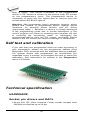
Universal 48-pindrive Programmer,
expandable up to 256.
866
Universal 48-pindrive Programmer with USB/LPT interface and ISP
capability
864
Universal 48-pindrive Programmer
844USB
Universal 40-pindrive Programmer with USB interface and ISP
capability
844A
Universal 40-pindrive Programmer with ISP capability
848
Universal Memory Programmer
848A
Universal Memory Programmer
849
MCS51 Series and Atmel AVR Microcontrollers Programmer with ISP
capability
COPYRIGHT © 1997 - 2005
B+K Precision Corporation
This document is copyrighted by B+K Precision, Yorba Linda California. All rights reserved. This document or any part of it may not
be copied, reproduced or translated in any form or in any way without
the prior written permission of B+K Precision
The control program is copyright B+K Precision, Yorba Linda California. The control program or any part of it may not be analyzed,
disassembled or modified in any form, on any medium, for any purpose.
Information provided in this manual is intended to be accurate at the
moment of release, but we continuously improve all our products.
Please consult manual on www.bkprecision.com .
B+K Precision assumes no responsibility for misuse of this manual.
B+K Precision reserves the right to make changes or improvements to
the product described in this manual at any time without notice. This
manual contains names of companies, software products, etc., which
may be trademarks of their respective owners. B+K Precision respects
those trademarks.
2
How to use this manual
This manual explains how to install the control program and
how to use your programmer. It is assumed that the user has
some experience with PCs and installation of software. Once
you have installed the control program we recommend you
consult the context sensitive HELP within the control program
rather than the printed User's Manual. Revisions are
implemented in the context sensitive help before the printed
Users Manual.
Note: Because this User's manual is common for more than
one B+K Precision programmers, read section(s) respective
programmer you have bought, please.
This manual contains two main sections:
Quick Start
Read this section if you are an experienced user. You will find
only specific information regarding installation of the control
program and use of your programmer. For more detailed
instructions you may read the Description in detail section or
the Troubleshooting chapter for the respective programmer.
Detailed description
Read this section for the respective programmer if you are a
less experienced user or if you need detailed information. You
may find some less relevant features of programmer described
here, but all programmer features are described in this section
along with details regarding installation of the control program.
Read this section to explore all of the features provided by your
programmer.
_____________________________________
Please, download actual version of manual from
B+K Precision WEB site (www.bkprecision.com), if current one
will be out of date.
3
Table of contents
How to use this manual.................................................................. 3
Introduction....................................................................................... 7
Products configuration ................................................................. 10
PC requirements .......................................................................... 10
Quick Start ...................................................................................... 12
Detailed description ....................................................................... 14
865.................................................................................................... 15
Introduction .................................................................................. 16
865 elements ............................................................................... 19
Connecting 865 to the PC............................................................ 20
Manipulation with the programmed device .................................. 21
In-system serial programming by 865.......................................... 21
Self test and Calibration............................................................... 23
Technical specification................................................................. 23
866.................................................................................................... 29
Introduction .................................................................................. 30
866 elements ............................................................................... 32
Connecting 866 to the PC............................................................ 33
Manipulation with the programmed device .................................. 34
In-system serial programming by 866.......................................... 34
Multiprogramming by 866 ............................................................ 36
Selftest and calibration................................................................. 36
Technical specification................................................................. 37
864.................................................................................................... 42
Introduction .................................................................................. 43
864 elements ............................................................................... 45
Connecting 864 to the PC............................................................ 46
Manipulation with the programmed device .................................. 47
Self test and Calibration............................................................... 47
Technical specification................................................................. 48
844USB ............................................................................................ 52
Introduction .................................................................................. 53
844USB elements ........................................................................ 55
Connecting 844USB to PC .......................................................... 56
Manipulation with the programmed device .................................. 56
In-system serial programming by 844USB .................................. 56
Selftest and calibration................................................................. 58
Technical specification................................................................. 58
844A ................................................................................................. 63
Introduction .................................................................................. 64
844A elements ............................................................................. 66
Connecting 844A to PC ............................................................... 67
Manipulation with the programmed device .................................. 67
In-system serial programming by 844A ....................................... 68
Self test and calibration................................................................ 69
Technical specification................................................................. 70
848.................................................................................................... 74
Introduction .................................................................................. 75
848 elements ............................................................................... 76
4
Connecting 848 programmer to PC..............................................77
Manipulation with the programmed device ...................................77
Self test and calibration ................................................................78
Technical specification .................................................................78
848A .................................................................................................82
Introduction...................................................................................83
848A elements..............................................................................84
Connecting 848A programmer to PC ...........................................84
Manipulation with the programmed device ...................................85
Technical specification .................................................................86
849 ....................................................................................................89
Introduction...................................................................................90
849 elements ................................................................................92
849 elements ................................................................................92
Connecting 849 programmer to PC..............................................92
Manipulation with the programmed device ...................................93
In-System serial programming by 849..........................................93
Selftest and calibration .................................................................95
Technical specification .................................................................95
Software...........................................................................................99
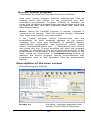
The programmer software ..........................................................100
File..............................................................................................102
Buffer ..........................................................................................107
Device.........................................................................................113
Programmer................................................................................137
Options .......................................................................................142
Help ............................................................................................146
Common notes ..............................................................................149
Software .....................................................................................150
Hardware ....................................................................................151
ISP (In-System Programming)....................................................152
Other...........................................................................................161
Troubleshooting and warranty ....................................................164
Throubleshooting........................................................................165
If you have an unsupported target device ..................................166
Warranty terms ...........................................................................167
Appendix........................................................................................169
Appendix A - Device Problem Report form.................................170
Appendix C - AlgOR service.......................................................171
5
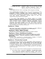
Conventions used in the manual
References to the control program functions are in bold, e.g.
Load, File, Device, etc. References to control keys are written
in brackets <>, e.g. <F1>.
Terminology used in the manual:
Device
any kind of programmable integrated circuits or
programmable devices
ZIF socket Zero Insertion Force socket used for insertion of
target device
Buffer
part of memory or disk, used for temporary data
storage
Printer port type of port of PC (parallel), which is
primarily dedicated for printer connection.
HEX data format - format of data file, which may be read with
standard text viewers; e.g. byte 5AH is stored as
characters '5' and 'A', which mean bytes 35H and
41H. One line of this HEX file (one record)
contains start address, data bytes and all records
are secured with checksum.
6
Introduction
7
This user's manual covers some B+K Precision programmers:
865, 866, 864, 844USB, 844A, 848, 848A and 849.
865 is a universal programmer and logic IC tester with 48
powerful pindrivers in base configuration, expandable up to
256. This design allows to easily adding new devices to the
device list. 865 provides very competitive price but excellent
hardware design for reliable programming. Best "value for
money" in this class.
866 is a fast universal USB/LPT interfaced universal
programmer and logic IC tester with 48 powerful pindrivers.
Using build-in in-circuit serial programming (ISP) connector the
programmer is able to program ISP capable chips in-circuit.
This design allows easily add new devices to the device list.
866 is a true universal and a true low cost programmer,
providing one of the best "value for money" in today's market.
864 is a universal programmer and logic IC tester with 48
powerful pindrivers. This design allows to easily adding new
devices to the device list. 864 is a true universal and a true low
cost programmer, providing one of the best "value for money"
in today's market.
844USB is a small, fast and powerful USB interfaced
programmer of all kinds of programmable devices. Using buildin in-circuit serial programming (ISP) connector the
programmer is able to program ISP capable chips in-circuit. It
has design, which allows easily add new devices to the device
list. Nice "value for money" in this class.
844A is a small, fast and powerful programmer of all kinds of
programmable devices. Using build-in in-circuit serial
programming (ISP) connector the programmer is able to
program ISP capable chips in-circuit. It has design, which
allows to easily adding new devices to the device list. Nice
"value for money" in this class.
848 is a small and powerful EPROM, EEPROM, Flash EPROM
and serial EEPROM programmer and static RAM tester,
designed for professional mobile applications. In addition, 848
programmer
with
auxiliary
modules
support
also
microprocessors (MCS48, MCS51, PIC, AVR), GALs, etc.
Programmer can work with 'true LV' device too - from 2V.
848A is a little and powerful programmer for EPROM,
EEPROM, Flash EPROM, NVRAM, serial EEPROM and static
RAM tester.
849 is little, powerful and very fast portable programmer for
MCS51 series and Atmel AVR Microcontrollers with ISP
8
capability. 849 enables also programming serial EEPROM with
interface types IIC (24Cxx), Microwire (93Cxx) and SPI
(25Cxx).
All our programmers work with almost any IBM PC Pentium
compatible or higher, portable or desktop personal computers.
No special interface card is required to connect to the PC,
since programmers use the parallel (printer) port or USB port.
All programmers function flawlessly on systems running
Windows 95/98/Me/NT/2000/XP.
All programmers are driven by an easy-to-use, control
program with pull-down menus, hot keys and online help.
Control program is common for all these B+K PRECISION
programmers (865, 866, 864, 844USB, 844A, 848, 848A and
849).
Advanced design, including protection circuits, original brand
components and careful manufacturing allows us to provide a
one-year warranty on parts and labor for these programmers
(limited 25,000 cycle warranty on ZIF socket).
Free additional services:
• free technical support (phone/fax/e-mail).
• free lifetime software update via Web site.
Free software updates are available from our
Internet address www.bkprecision.com
We also offer the following new services in our customer
support program: Keep-Current and AlgOR.
• Keep-Current is a service by which B+K PRECISION ships
to you the latest version of the control program for
programmer and the updated user documentation. A KeepCurrent service is your hassle-free guarantee that you always
have access to the latest software and documentation, at
minimal cost.
• AlgOR (Algorithm On Request) service allows you to receive
from B+K PRECISION software support for programming
devices not yet available in the current device list.
Note: We don’t recommend use programmers 864, 848 and
848A for In-circuit programming.
9
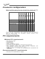
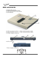
Products configuration
866
864
844USB
844A
848A
848
849
programmer
LPT cable
USB cable
power supply
diagnostic POD
ISP cable
ZIF anti-dust cover
User’s manual
Quick Guide
registration card
shipping case
865
Before installing and using your programmer, please carefully
check that your package includes all next mentioned parts.
•
•
•
•
•
•
•
•
•
•
•
•
•
•
•
•
•
•
•
•
•
•
•
•
•
•
•
•
•
•
•
•
•
•
•
•
•
•
•
•
•
•
•
•
•
•
•
•
•
•
•
•
•
•
•
•
•
•
•
•
•
•
•
•
•
•
•
If you find any discrepancy with respective parts list and/or if
any of these items are damaged, please contact your
distributor immediately.
PC requirements
Minimal PC requirements
• PC Pentium 166
• 32MB RAM
• one CD drive
• HDD, 40 MB free space
• operating system Windows 95/98/Me/NT/2000/XP
• one parallel (LPT) port with nothing attached (for
programmers connected via LPT port)
• USB port ver. 1.1 or later (for programmers connected via
USB port)
Recommended PC requirements
• Pentium PC III 800 MHz or higher
10
• 256 MB free RAM
• one CD drive
• HDD, 50 MB free space
• operating system: Windows XP
• LPT printer port supporting EPP/ECP modes (for
programmers connected via LPT port)
• USB port ver. 1.1 or later (for programmers connected via
USB port)
Note: For convenience, we suggest that you use a
supplementary multi I/O card to provide an additional printer
port (LPT2 for example), in order to avoid sharing the same
LPT port between printer and programmer.
11
Quick Start
12
Installing programmer hardware
• switch off the PC and programmer
• connect the communication port of programmer to a printer
port of PC using cable supplied
• switch on the PC
• connect the connector of the power supply adapter to the
programmer
Installing the programmer software
Run the installation program from the CD (Setup.exe) and
follow the on-screen instructions. Please, for latest information
about the programmer hardware and software see
www.bkprecision.com .
Using programmer software
Launch PG4UW.exe to enter the control program. The menu
Device contains the device manipulation commands. The
menu File contains commands for files and directories. The
menu Buffer is to be used for buffer manipulation.
Programming a device - the shortest way
Use the hot key <Alt+F5> to input the device name and/or
manufacturer to select the desired type of target device. If you
want to copy an existing device, insert it into the ZIF socket of
the programmer and then press key <F7>. If you want to
program a target device with data from a disk press key <F3>
and read the appropriate file into the buffer. Then insert your
target device into the ZIF socket. To check if the device is
blank - press key <F6>. Now you can program the device by
pressing key <F9>. After programming you may perform
additional verification by pressing key <F8>.
13
Detailed description
14
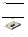
865
15
Introduction
865 is a new generation of Windows 95/98/Me/NT/2000/XP
based B+K PRECISION universal programmers built to meet
the rigorous demands of the leading engineers and
programming centers.
865 supports all kinds of types and silicon technologies of
programmable devices. It provides very competitive price but
excellent hardware design for reliable programming. Best
"value for money" in this class.
865 interfaces with the IBM PC Pentium compatible or higher,
portable or desktop personal computers. Programmer allows
you to directly connect to your PC through any standard
parallel (printer) port (no special interface card needed). We
recommend use parallel (printer) port on PCI bus, IEEE
1284 compatible (ECP/EPP). The 865 control program
support standard IEEE1284 also.
865 offer very fast programming due high-speed FPGA driven
hardware and support of ECP/EPP parallel port. Consequently
and due special protocol is communication between PC and
865 programmer fast and very reliable. The programming
AT29C040A takes about 28 seconds it is faster than most its
competitors. As a result, this programmer is optional solution
for middle quantities programming in production or
programming centers.
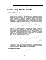
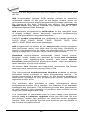
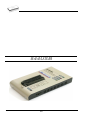
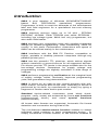
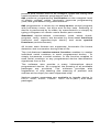
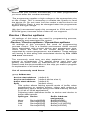
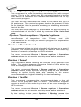
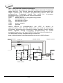
Scheme of 865 programming system
865, base configuration
• 865, base unit
• 865, DIL48 socket module
For following text, term 865 means 865 in base configuration.
16
865 has 48 powerful pindrivers in base unit, expandable up to
256 pindrivers using "pindriver expansion" modules. Advanced
pin drivers incorporate high-quality high-speed circuitry to
deliver programming and testing performance without
overshoot or ground bounce for all device technologies. Pin
drivers operate down to 1.8V so you'll be ready to program the
full range of today's advanced low-voltage devices.
Modular design of 865 allows adapting the programmer
according to customers needs either as very flexible universal
programmer for laboratory or high efficient multi-programmer in
production line. Multiprogramming capability for most of
supported devices is accomplished by using "multiple socket"
modules.
Powerful pindriver provides logic level, pull-up/pull-down, clock,
ground, one VCC supply and two programming supply and,
certainly read, on each of all 48 pins independently. This
advanced design give it the ability to program almost every
programmable device in DIL up to 48 pins without adapter or
family specific module. Support for today and tomorrow
programmable devices gives engineers the freedom to choose
the optimum device for new design.
865 isn't only programmer, but also tester of TTL/CMOS logic
ICs and memories. Furthermore, it allows generate of userdefinable test pattern sequences.
The programmer has on-board intelligence, comprise of
powerful Microcontroller system and support devices. 865 has
been designed for multitasking operating systems and is
able to perform time-critical programming sequences
independently of the PC operating system status and without
being interrupted by any another parallel process running on
the PC. Consequently, 865 works without any problem on
systems running Windows 95/98/Me/NT/2000/XP.
The programmer performs device insertion test (wrong or
backward position) and contact check (poor contact pin-tosocket) before it programs each device. These capabilities,
supported by over current protection and signature-byte check
help prevent chip damage due to operator error.
Built-in protection circuits eliminate damage of programmed
device due to mains supply fluctuations, communication error
or if PC is frozen. In event of such errors Microcontroller in
programmer performs, independently on the PC, exactly
specified sequence of steps, so that programmed target device
remains intact. Programmer's hardware offers enough
resources for self test, that control program is any time be
able to check pindrivers, present and correct level of all
17
voltages, check the timing and communication between
programmer and PC.
An optimally designed printed circuit minimizes negative
programming effects at the socket (such as ground bouncing,
supply voltage instability). All the inputs of the 865
programmer, including the ZIF socket, connection to PC and
power supply input, are protected against ESD to protect the
programmer and programmed circuits against damage due
ESD.
865 performs programming verification at the marginal level
of supply voltage, which, obviously, improves programming
yield, and guarantees long data retention.
Various socket converters are available to handle device in
PLCC, SOIC, PSOP, SSOP, TSOP, TSSOP, TQFP, QFN
(MLF), SDIP, BGA and other packages.
Devices with more than 48 pins are supported by
• pindriver expansion module and universal single socket
module
• simple special package converters
865 programmer is driven by an easy-to-use control program
with pull-down menu, hot keys and on-line help. Selecting of
device is performed by its class, by manufacturer or simply by
typing a fragment of vendor name and/or part number.
Standard device-related commands (read, blank check,
program, verify, erase) are boosted by some test functions
(insertion test, signature-byte check), and some special
functions (autoincrement, production mode - start immediately
after insertion of chip into socket).
All known data formats are supported. Automatic file format
detection and conversion during load of file.
The rich-featured autoincrement function enables to assign
individual serial numbers to each programmed device - or
simply increments a serial number, or the function enables to
read serial numbers or any programmed device identification
signatures from a file.
The software also provide a many informations about
programmed device. As a special, the drawing of all available
packages are provided. The software provide also explanation
of chip labeling (the meaning of prefixes and suffixes at the
chips) for each supported chip.
It is important to remember that in most cases new devices
require only a software upgrade since the 865 has 48 true
18
pin drivers, which can perform as required under program
control. With our prompt service new devices can be added to
the current list within hours!
Advanced design including protection circuits, original brand
components and careful manufacturing allows us to provide a
one-year warranty on parts and labor for the 865 (limited
25,000-cycle warranty on ZIF socket).
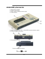
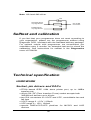
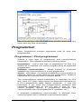
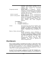
865 elements
DIL48 socket module with 48 pin ZIF socket
LED indicator power/sleep
LED indicators for work result
YES! Button
Connector for PC <-> 865 communication cable
Power supply connector
Internal use connector
Power supply connector
19
Note: Due to low power consumption of 865 in inactive mode,
it doesn't require power switch. When the power LED indicator
glows with a low intensity, the 865 is in inactive mode.
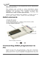
Connecting 865 to the PC
Switch off PC and programmer. Insert the communication
cable included with your 865 programmer package to a free
printer port on your PC. If your computer is equipped with only
one printer port, substitute the programmer cable for the printer
cable. Connect the opposite cable end to the programmer.
Screw on both connectors to counter-connectors. This is very
important. It may be uncomfortable to switch between printer
cable and programmer cable, though it is not recommended to
operate the 865 programmer through a mechanical printer
switch. Use of an electronic printer switch is impossible. But
you can install a second multi-I/O in your computer, thus
obtaining a supplementary printer port, says LPT2. So your
printer may remain on LPT1 while the programmer on LPT2.
Switch on the PC.
Connect the mains connector of the power supply (or the wallplug power supply itself) to a mains plug, and then connect the
mini-DIN connector to the programmer's connector labeled
"12VAC". At this time all 'work result' LEDs (and 'POWER'
LED) light up successive and then switch off. Once the
POWER LED lights with low brightness then the 865
programmer is ready to run.
Next run the control program for 865.
Caution! If you don't want to switch off your PC when
connecting the 865, proceed as follows:
• When connecting the programmer to the PC: FIRST insert
the communications cable and THEN the power-supply
connector.
• When disconnecting the programmer from the PC: FIRST
disconnect the power-supply connector and THEN the
communication cable.
From 865's point of view the connecting and disconnecting
sequence is irrelevant. Protection circuits on all programmer
inputs keep it safe. But think of your PC please.
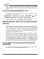
Problems related to the 865
interconnection, and their removing
If you have any problems with 865
see section Common notes please.
20
PC
PC interconnection,
Manipulation with the programmed
device
After selection of desired device for your work, you can insert
into the open ZIF socket (the lever is up) and close socket (the
lever is down). The correct orientation of the programmed
device in ZIF socket is shown on the picture near ZIF socket
on the programmer's cover. The programmed device is
necessary to insert into the socket also to remove from the
socket when LED BUSY light off.
Note: Programmer's protection electronics protect the target
device and the programmer itself against either short or longterm power failures and, partly, also against a PC failure.
However, it is not possible to grant the integrity of the target
device due to incorrect, user-selected programming
parameters. Target device may be not destroyed by forced
interruption of the control program (reset or switch-off PC), by
removing the physical connection to the programmer, but the
content of actually programmed cell may remains undefined.
Don't unplug the target device from the ZIF socket during work
with devices (LED BUSY shine).
In-system serial programming by
865
For ISP programming by 865 is necessary change DIL48
socket module by ISP module.
ISP module attached to 865 programmer is manual operated
ISP programming solution, suitable for development and
low/middle volume production application.
Optimized
advanced
pindriver
deliver
programming
performance without overshoot or ground bounce for all device
technologies. Pin drivers operate down to 1.8V so you'll be
ready to program the full range of today's advanced lowvoltage devices.
The ISP programming solution performs programming
verification at the marginal level of supply voltage, which,
obviously, improves programming yield, and guarantees long
data retention.
The ISP programming solution provide also the power supply
for the target system.
21
This ISP programming solution provides very competitive price
but excellent hardware design for reliable programming.
This ISP programming solution is driven by the same software
as the 865 programmer. The software provide full information
for ISP implementation: Description of ISP connector pins for
currently selected chip, recommended target design around incircuit programmed chip and other necessary information.
For general definition, recommendation and direction about
ISP see section Common notes / ISP please.
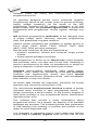
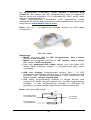
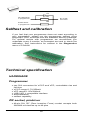
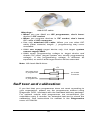
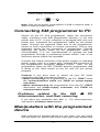
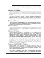
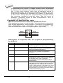
Description of ISP connector
7
5
3
1
14 12 10 8
6
4
2
13 11
9
Front view at ISP connector.
Specification of ISP connector pins depends on the device,
which you want to program. You can find it in the control SW
for programmer (PG4UW), menu Device / Device Info
(Ctrl+F1). Be aware, the ISP programming way of respective
device must be selected. It is indicated by (ISP) suffix after
name of selected device.
These specifications correspond with application notes
published of device manufacturers. Used application notes you
may find on www.bkprecision.com, section application notes.
Note: Pin no. 1 is signed by triangle scratch on ISP cable
connectors.
865 ISP cable
Warnings:
22
• Use only attached ISP cable. When you use other ISP
cable (other material, length…), programming may occur
unreliable.
• 865 can supply programmed device (pin 1 of ISP
connector) and target system (pin 5, 13, 14 of ISP
connector) with limitation (see Technical specification / ISP
connector), but target system cannot supply 865.
• 865 apply programming voltage to target device and
checks his value (target system can modify programming
voltage). If the programming voltage is different as
expected, no action with target device will be executed.
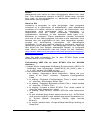
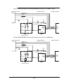
Note: H/L/read driver on pins 3 and 10
1n0
ISP
connector
H/L/read
driver
315R
H/L/read driver on pins 2, 4, 6 and 8
ISP
connector
H/L/read
driver
150R
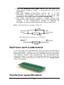
Self test and Calibration
If you feel that your programmer does not react according to
your expectation, please run the programmer self test using
Diagnostic POD, enclosed with the standard delivery package.
For optimal results with programmer we recommend you
undertake every 6 months, an extended test and to check the
calibration. See instructions for self test in the Diagnostics
menu of PG4UW.
Technical specification
23
HARDWARE
Base unit, DACs
• FPGA based IEEE 1284 slave printer port, up to 1MB/s
transfer rate
• on-board powerful microprocessor (20MHz) supported by
FPGA based state machine, 20MHz powered
• three D/A converters for VCCP, VPP1, and VPP2,
controllable rise and fall time
• VCCP range 0..8V/1A
• VPP1, VPP2 range 0..26V/1A
• auto calibration
• self test capability
• protection against surge and ESD on power supply input,
parallel port connection
• banana jack for ESD wrist straps
Socket, pindriver
• pin drivers: 48 as standard max. 256
• 1x VCC, 2x VPP can be connected to each pin
• perfect ground for each pin
• FPGA based TTL driver provides H, L, CLK, pull-up, pulldown on all pindriver pins
• analog pindriver output level selectable from 1.8 V up to 26V
• current limitation, over current shutdown, power failure
shutdown
• ESD protection on each pin of socket (IEC1000-4-2: 15kV air,
8kV contact)
• continuity test: each pin is tested before every programming
operation
Socket, base configuration
• 48-pin DIL ZIF (Zero Insertion Force) socket accepts both
300/600 mil devices up to 48-pin
DEVICE SUPPORT
865 with DIL48 socket module
• EPROM: NMOS/CMOS, 2708*, 27xxx and 27Cxxx series,
with 8/16 bit data width, full support for LV series
• EEPROM: NMOS/CMOS, 28xxx, 28Cxxx, 27EExxx series,
with 8/16 bit data width
• Flash EPROM: 28Fxxx, 29Cxxx, 29Fxxx, 29BVxxx, 29LVxxx,
29Wxxx, 49Fxxx series, from 256Kbit to 32Mbit, with 8/16 bit
data width, full support for LV series
24
• Serial E(E)PROM: 24Cxxx, 24Fxxx, 25Cxxx, 45Dxxx,
59Cxxx, 25Fxxx, 25Pxxx, 85xxx, 93Cxxx, NVM3060, MDAxxx
series, full support for LV series
• Configuration (EE)PROM: XCFxxx, XC17xxxx, XC18Vxxx,
EPCxxx, AT17xxx, 37LVxx
• 1-Wire E(E)PROM: DS1xxx, DS2xxx
• PROM: AMD, Harris, National, Philips/Signetics, Tesla, TI
• NV RAM: Dallas DSxxx, SGS/Inmos MKxxx, SIMTEK
STKxxx, XICOR 2xxx, ZMD U63x series
• PLD: Altera: MAX 3000A, MAX 7000A, MAX 7000B, MAX
7000S, MAX7000AE
• PLD: Lattice: ispGAL22V10x, ispLSI1xxx, ispLSI1xxxEA,
ispLSI2xxx,
ispLSI2xxxA,
ispLSI2xxxE,
ispLSI2xxxV,
ispLSI2xxxVE, ispLSI2xxxVL, LC4xxxB/C/V/ZC, M4-xx/xx,
M4A3-xx/xx, M4A5-xx/xx, M4LV-xx/xx
• PLD: Xilinx: XC9500, XC9500XL, XC9500XV, CoolRunner
XPLA3, CoolRunner-II
• other PLD: SPLD/CPLD series: AMI, Atmel, AMD-Vantis,
Gould, Cypress, ICT, Lattice, NS, Philips, STM, VLSI, TI
• Microcontrollers 48 series: 87x41, 87x42, 87x48, 87x49,
87x50 series
• Microcontrollers 51 series: 87xx, 87Cxxx, 87LVxx, 89Cxxx,
89Sxxx, 89LVxxx, all manufacturers, Philips 87C748..752
series, Philips LPC series, Cygnal/Silicon Laborat. C8051
series
• Microcontrollers
Intel
196
series:
87C196
KB/KC/KD/KT/KR/...
• Microcontrollers Atmel AVR: AT90Sxxxx, ATtiny, ATmega
series
• Microcontrollers Cypress: CY8Cxxxxx
• Microcontrollers ELAN: EM78Pxxx
• Microcontrollers Microchip PICmicro: PIC10xxx, PIC12xxx,
PIC16xxx, PIC17Cxxx, PIC18xxx, dsPIC series
• Microcontrollers Motorola: 68HC05, 68HC08, 68HC11 series
• Microcontrollers National: COP8xxx series
• Microcontrollers NEC: uPD78Pxxx series
• Microcontrollers Scenix (Ubicom): SXxxx series
• Microcontrollers SGS-Thomson: ST6xx, ST7xx, ST10xx
series
• Microcontrollers TI: MSP430 and MSC121x series
• Microcontrollers ZILOG: Z86/Z89xxx and Z8xxx series
• Microcontrollers other: EM Microelectronic, Fujitsu, Goal
Semiconductor, Princeton, Macronix, Winbond, Hitachi,
Holtek, Infineon(Siemens), NEC, Samsung, Toshiba, ...
I.C. Tester
• TTL type: 54,74 S/LS/ALS/H/HC/HCT series
• CMOS type: 4000, 4500 series
• static RAM: 6116.. 624000
• user definable test pattern generation
25
865 with ISP module
• Serial E(E)PROM: IIC series
• Microcontrollers Atmel: AT89Sxxx, AT90Sxxxx, ATtiny,
ATmega series
• Microcontrollers Cypress: CY8C2xxxx
• Microcontrollers Elan: EM78Pxxx
• Microcontrollers EM Microelectronic: 4 and 8 bit series
• Microcontrollers Microchip PICmicro: PIC10xxx, PIC12xxx,
PIC16xxx, PIC17xxx, PIC18xxx, dsPIC series
• Microcontrollers Motorola/Freescale: HC08 GT, LJ, QY, QT
series
• Microcontrollers Philips: LPC series
• Microcontrollers TI: MSP430
• PLD: Lattice: ispGAL22xV10x, ispLSI1xxxEA, ispLSI2xxxE,
ispLSI2xxxV, ispLSI2xxxVE, ispLSI2xxxVL, M4-xx/xx, M4LVxx/xx, M4A3-xx/xx, M4A5-xx/xx, LC4xxxB/C/V/ZC
• Various PLD (also by Jam player/JTAG support):
• Altera: MAX 3000A, MAX 7000A, MAX 7000B, MAX 7000S,
MAX 9000, MAX II
• Xilinx: XC9500, XC9500XL, XC9500XV, CoolRunner XPLA3,
CoolRunner-II
Notes:
• Devices marked * are obsolete, programming with additional
module
• For all supported devices see actual Device list
Package support
• package support includes DIP, PLCC, SOIC, PSOP, SSOP,
TSOP, TSSOP, TQFP, QFN (MLF), SDIP, BGA and other
• support all devices in DIP with default socket
• support devices in non-DIP packages up to 48 pins with
universal adapters
• programmer is compatible with third-party adapters for nonDIP support
Programming speed
Device
27C010
AT29C040A
AM29F040
PIC16C67
PIC18F452
Conditions:
Operation
programming and verify
programming and verify
programming and verify
programming and verify
programming and verify
Time
21 sec
31 sec
35 sec
10 sec
4 sec
P4, 2,4GHz,ECP, Windows XP
26
SOFTWARE
• Algorithms: only manufacturer approved or certified
algorithms are used. Custom algorithms are available at
additional cost.
• Algorithm updates: software updates are available approx.
every 2 weeks, free of charge.
• Main features: revision history, session logging, on-line help,
device and algorithm information
Device operations
• standard:
• intelligent device selection by device type, manufacturer or
typed fragment of part name
• automatic ID-based selection of EPROM/Flash EPROM
• blank check, read, verify
• program
• erase
• configuration and security bit program
• illegal bit test
• checksum
• security
• insertion test, reverse insertion check
• contact check
• ID byte check
• special
• production mode (automatic start immediately after device
insertion)
• auto device serial number increment
• statistic
• count-down mode
Buffer operations
• view/edit, find/replace
• fill/copy, move, byte swap, word/dword split
• checksum (byte, word)
• print
Supported file formats
• unformatted (raw) binary
• HEX: Intel, Intel EXT, Motorola S-record, MOS, Exormax,
Tektronix, ASCII-space-HEX
• Altera POF, JEDEC (ver. 3.0.A), eg. from ABEL, CUPL,
PALASM, TANGO PLD, OrCAD PLD, PLD Designer
ISDATA, etc.
27
PC system requirements
See section Introduction/ PC requirements
GENERAL
• operating voltage 12..15V AC, max. 1A or 15..18V DC, max.
1A
• power consumption max. 12W active, 2.5W inactive
• dimensions 275x157x58 mm (10.8x6.2x2.3 inch)
• weight (without external adapter) 1.8kg (4 lb)
• temperature 5°C ÷ 40°C (41°F ÷ 104°F)
• humidity 20%..80%, non condensing
Package included
• 865, base unit
• 865, DIL48 socket module
• connection cable PC-programmer
• diagnostic POD for self test
• anti-dust cover for ZIF socket
• switched power adapter 100..240V AC/15V DC/1A
• user manual
• software
• registration card
• transport case
Additional services
• AlgOR
• free technical support (phone/fax/e-mail).
• free lifetime software update via Web site.
28
866
29
Introduction
866 is a first member of new USB-compatible generation of
Windows 95/98/Me/NT/2000/XP based B+K PRECISION
universal programmers built to meet the strong demand of
the developers’ community for the fast, the all programmer
user community of users.
866 supports all kinds of types and silicon technologies of
today and tomorrow programmable devices without familyspecific module. Using build-in in-circuit serial programming
(ISP) connector the programmer is able to program ISP
capable chips in circuit.
866 isn't only programmer, but also tester of TTL/CMOS logic
ICs and memories. Furthermore, it allows generating userdefinable test pattern sequences.
866 provides very competitive price but excellent hardware
design for reliable programming. Probably it has best "value for
money" programmer in this class.
866 provides very fast programming due to high-speed
FPGA driven hardware and execution of time-critical routines
inside of the programmer. It is least fast than competitors in
this category.
866 interfaces with the IBM PC Pentium compatible or higher,
portable or desktop personal computers through USB (2.0) port
or any standard parallel (printer) port. Programmer also
supports IEEE1284 (ECP/EPP) high-speed parallel port.
Support of USB/LPT port connection give you choice to
connect the 866 programmer to any PC, from latest notebook
to older desktop without USB port.
866 has a FPGA based totally reconfigurable 48 powerful TTL
pindrivers provide H/L/pull_up/pull_down and read capability
for each pin of socket. Advanced pindrivers incorporate highquality high-speed circuitry to deliver signals without
overshoot or ground bounce for all supported devices. Pin
drivers operate down to 1.8V so you'll be ready to program the
full range of today's advanced low-voltage devices.
866 performs device insertion test (wrong or backward
position) and contact check (poor contact pin-to-socket)
before it programs each device. These capabilities, supported
by overcurrent protection and signature-byte check help
prevent chip damage due to operator error.
Built-in protection circuits eliminate damage of programmer
and/or programmed device due environment or operator
30
failure. All the inputs of the 866 programmer, including the ZIF
socket, connection to PC and power supply input, are
protected against ESD up to 15kV.
866 programmer performs programming verification at the
marginal level of supply voltage, which, obviously, improves
programming yield, and guarantees long data retention.
Various socket converters are available to handle device in
PLCC, SOIC, PSOP, SSOP, TSOP, TSSOP, TQFP, QFN
(MLF), SDIP, BGA and other packages.
866 programmer is driven by an easy-to-use control program
with pull-down menu, hot keys and on-line help. Selecting of
device is performed by its class, by manufacturer or simply by
typing a fragment of vendor name and/or part number.
Standard device-related commands (read, blank check,
program, verify, erase) are boosted by some test functions
(insertion test, signature-byte check), and some special
functions (autoincrement, production mode - start immediately
after insertion of chip into socket).
All known data formats are supported. Automatic file format
detection and conversion during load of file.
The rich-featured autoincrement function enables to assign
individual serial numbers to each programmed device - or
simply increments a serial number, or the function enables to
read serial numbers or any programmed device identification
signatures from a file.
The software also provides a many informations about
programmed device. As a special, the drawing of all available
packages are provided. The software provide also explanation
of chip labeling (the meaning of prefixes and suffixes at the
chips) for each supported chip.
It is important to remember that in most cases new devices
require only a software update due to the 866 is truly
universal programmer. With our prompt service you can have
new devices can be added to the current list within hours!
Advanced design including protection circuits, original brand
components and careful manufacturing allows us to provide a
three-year warranty on parts and labor for the 866 (limited
25,000-cycle warranty on ZIF socket).
31
866 elements
48 pin ZIF socket
LED indicator power/sleep
LED indicators for work result
YES! Button
LPT connector for PC <-> 866 communication cable
USB connector for PC <-> 866 communication cable
Power supply connector
ISP connector
Power supply connector
32
Note: Due to low power consumption of 866 in inactive state, it
doesn't require power switch. When the power LED indicator
glows with a low intensity the 866 is in inactive mode.
Connecting 866 to the PC
Using LPT port
Switch off PC and programmer. Insert the communication
cable included with your 866 programmer package to a free
printer port on your PC. If your computer is equipped with only
one printer port, substitute the programmer cable for the printer
cable. Connect the opposite cable end to the programmer.
Screw on both connectors to counter-connectors. This is very
important. It may be uncomfortable to switch between printer
cable and programmer cable, though it is not recommended to
operate the 866 programmer through a mechanical printer
switch. Use of an electronic printer switch is impossible. But
you can install a second multi-I/O in your computer, thus
obtaining a supplementary printer port, says LPT2. So your
printer may remain on LPT1 while the programmer on LPT2.
Switch on the PC.
Connect the mains connector of the power supply to a mains
plug, and then connect the mini-DIN connector to the
programmer's connector labeled "15VDC". At this time all 'work
result' LEDs (and 'POWER' LED) light up successive and then
switch off. Once the POWER LED lights with low brightness
then the 866 programmer is ready to run.
Next run the control program for 866.
Caution! If you don't want to switch off your PC when
connecting the 866, proceed as follows:
• When connecting the programmer to the PC: FIRST insert
the communications cable and THEN the power-supply
connector.
• When disconnecting the programmer from the PC: FIRST
disconnect the power-supply connector and THEN the
communication cable.
From 866's point of view the connecting and disconnecting
sequence is irrelevant. Protection circuits on all programmer
inputs keep it safe. But think of your PC please.
Using USB port
In this case, order of connecting USB cable and power supply
to programmer is irrelevant.
33
Problems related to the 866
interconnection, and their removing
If you have any problems with 866
see section Common notes please.
PC
PC interconnection,
Manipulation with the programmed
device
After selection of desired device for your work, you can insert
into the open ZIF socket (the lever is up) and close socket (the
lever is down). The correct orientation of the programmed
device in ZIF socket is shown on the picture near ZIF socket
on the programmer's cover. The programmed device is
necessary to insert into the socket also to remove from the
socket when LED BUSY light off.
Note: Programmer's protection electronics protect the target
device and the programmer itself against either short or longterm power failures and, partly, also against a PC failure.
However, it is not possible to grant the integrity of the target
device due to incorrect, user-selected programming
parameters. Target device may be not destroyed by forced
interruption of the control program (reset or switch-off PC), by
removing the physical connection to the programmer, but the
content of actually programmed cell may remains undefined.
Don't unplug the target device from the ZIF socket during work
with device (LED BUSY shine).
In-system serial programming by
866
For general definition, recommendation and direction about
ISP see section Common notes / ISP please.
Description of 866 ISP connector
2
4
6
8 10
1
3
5
7
9
Front view at ISP connector of programmer.
Specification of ISP connector pins depends on the device,
which you want to program. You can find it in the control SW
34
for programmer (PG4UW), menu Device / Device Info
(Ctrl+F1). Be aware, the ISP programming way of respective
device must be selected. It is indicated by (ISP) suffix after
name of selected device.
These specifications correspond with application notes
published of device manufacturers. Used application notes you
may find on www.bkprecision.com.
Note: Pin no. 1 is signed by triangle scratch on ISP cable
connectors.
866 ISP cable
Warnings:
• When you use 866 as ISP programmer, don’t insert
device to ZIF socket.
• When you program devices in ZIF socket, don’t insert
ISP cable to ISP connector.
• Use only attached ISP cable. When you use other ISP
cable (other material, length…), programming may occur
unreliable.
• 866 can supply programmed device (pin 1 of ISP
connector) and target system (pin 5 of ISP connector)with
limitation (see Technical specification / ISP connector), but
target system cannot supply 866.
• 866 apply programming voltage to target device and
checks his value (target system can modify programming
voltage). If the programming voltage is different as
expected, no action with target device will be executed.
Note: H/L/read 866 driver
C1
R1
H/L/read driver
in programmer
pin of ISP
connector
R2
PU/PD driver
in programmer
35
Multiprogramming by 866
Attaching of more 866 programmers to the same PC (through
USB port) is achieved a powerful multiprogramming system
with as much chips supported as 866 can and without obvious
decreasing of programming speed. It is important to know,
there is a concurrent multiprogramming - each programmer
works independently and each programmer can program
different chip, if necessary.
During installation of PG4UW at Select Additional Tasks
window check, if is allowed install 866 multiprogramming
control support.
For start of 866 multiprogramming is necessary run special
control program pg4uwmc.exe. At this program user assign
866 to control programs, may load projects for all 866 and run
PG4UW for every connected and assigned 866.
Selftest and calibration
If you feel that your programmer does not react according to
your expectation, please run the programmer selftest using
Diagnostic POD, enclosed with the standard delivery package.
For optimal results with programmer we recommend you
undertake every 6 months, an extended test and to check the
calibration. See instructions for selftest in the Diagnostics
menu of PG4UW.
36
Technical specification
HARDWARE
Base unit, DACs
• USB 2.0 port
• FPGA based IEEE 1284 slave printer port, up to 1MB/s
transfer rate
• on-board intelligence: powerful microprocessor and FPGA
based state machine
• three D/A converters for VCCP, VPP1, and VPP2,
controllable rise and fall time
• VCCP range 0..8V/1A
• VPP1, VPP2 range 0..26V/1A
• autocalibration
• selftest capability
• protection against surge and ESD on power supply input,
parallel port connection
Socket, pindriver
• 48-pin DIL ZIF (Zero Insertion Force) socket accepts both
300/600 mil devices up to 48-pin
• pindrivers: 48 universal
• VCCP / VPP1 / VPP2 can be connected to each pin
• perfect ground for each pin
• FPGA based TTL driver provides H, L, CLK, pull-up, pulldown on all pindriver pins
• analog pindriver output level selectable from 1.8 V up to 26V
• current limitation, overcurrent shutdown, power failure
shutdown
• ESD protection on each pin of socket (IEC1000-4-2: 15kV air,
8kV contact)
• continuity test: each pin is tested before every programming
operation
37
ISP connector
• 10-pin male type with missinsertion lock
• 6 TTL pindrivers, provides H, L, CLK, pull-up, pull-down; level
H selectable from 1.8V up to 5V to handle all (low-voltage
including) devices.
• 1x VCCP voltage (range 2V..7V/100mA) and 1x VPP voltage
(range 2V..25V/50mA)
• programmed chip voltage (VCCP) with both source/sink
capability and voltage sense
• target system supply voltage (range 2V..6V/250mA)
DEVICE SUPPORT
Programmer, in ZIF socket
• EPROM: NMOS/CMOS, 2708*, 27xxx and 27Cxxx series,
with 8/16 bit data width, full support for LV series
• EEPROM: NMOS/CMOS, 28xxx, 28Cxxx, 27EExxx series,
with 8/16 bit data width
• Flash EPROM: 28Fxxx, 29Cxxx, 29Fxxx, 29BVxxx, 29LVxxx,
29Wxxx, 49Fxxx series, from 256Kbit to 32Mbit, with 8/16 bit
data width, full support for LV series
• Serial E(E)PROM: 24Cxxx, 24Fxxx, 25Cxxx, 45Dxxx,
59Cxxx, 25Fxxx, 25Pxxx, 85xxx, 93Cxxx, NVM3060, MDAxxx
series, full support for LV series
• Configuration (EE)PROM: XCFxxx, XC17xxxx, XC18Vxxx,
EPCxxx, AT17xxx, 37LVxx
• 1-Wire E(E)PROM: DS1xxx, DS2xxx
• PROM: AMD, Harris, National, Philips/Signetics, Tesla, TI
• NV RAM: Dallas DSxxx, SGS/Inmos MKxxx, SIMTEK
STKxxx, XICOR 2xxx, ZMD U63x series
• PLD: Altera: MAX 3000A, MAX 7000A, MAX 7000B, MAX
7000S, MAX7000AE
• PLD: Lattice: ispGAL22V10x, ispLSI1xxx, ispLSI1xxxEA,
ispLSI2xxx,
ispLSI2xxxA,
ispLSI2xxxE,
ispLSI2xxxV,
ispLSI2xxxVE, ispLSI2xxxVL, LC4xxxB/C/V/ZC, M4-xx/xx,
M4A3-xx/xx, M4A5-xx/xx, M4LV-xx/xx
• PLD: Xilinx: XC9500, XC9500XL, XC9500XV, CoolRunner
XPLA3, CoolRunner-II
• other PLD: SPLD/CPLD series: AMI, Atmel, AMD-Vantis,
Gould, Cypress, ICT, Lattice, NS, Philips, STM, VLSI, TI
• Microcontrollers 48 series: 87x41, 87x42, 87x48, 87x49,
87x50 series
• Microcontrollers 51 series: 87xx, 87Cxxx, 87LVxx, 89Cxxx,
89Sxxx, 89LVxxx, all manufacturers, Philips LPC series
• Microcontrollers
Intel
196
series:
87C196
KB/KC/KD/KT/KR/...
• Microcontrollers Atmel AVR: AT90Sxxxx, ATtiny, ATmega
series
38
• Microcontrollers Cypress: CY8Cxxxxx
• Microcontrollers ELAN: EM78Pxxx
• Microcontrollers Microchip PICmicro: PIC10xxx, PIC12xxx,
PIC16xxx, PIC17Cxxx, PIC18xxx, dsPIC series
• Microcontrollers Motorola: 68HC05, 68HC08, 68HC11 series
• Microcontrollers National: COP8xxx series
• Microcontrollers NEC: uPD78Pxxx series
• Microcontrollers Scenix (Ubicom): SXxxx series
• Microcontrollers SGS-Thomson: ST6xx, ST7xx, ST10xx
series
• Microcontrollers TI: MSP430 and MSC121x series
• Microcontrollers ZILOG: Z86/Z89xxx and Z8xxx series
• Microcontrollers other: EM Microelectronic, Fujitsu, Goal
Semiconductor, Hitachi, Holtek, Princeton, Macronix,
Winbond, Infineon(Siemens), NEC, Samsung, Toshiba, ...
Programmer, through ISP connector
• Serial E(E)PROM: IIC series
• Microcontrollers Atmel: AT89Sxxx, AT90Sxxxx, ATtiny,
ATmega series
• Microcontrollers Cypress: CY8C2xxxx
• Microcontrollers Elan: EM78Pxxx
• Microcontrollers EM Microelectronic: 4 and 8 bit series
• Microcontrollers Microchip PICmicro: PIC10xxx, PIC12xxx,
PIC16xxx, PIC17xxx, PIC18xxx, dsPIC series
• Microcontrollers Motorola/Freescale: HC08 GT, LJ, QY, QT
series
• Microcontrollers Philips: LPC series
• Microcontrollers TI: MSP430
• PLD: Lattice: ispGAL22xV10x, ispLSI1xxxEA, ispLSI2xxxE,
ispLSI2xxxV, ispLSI2xxxVE, ispLSI2xxxVL, M4-xx/xx, M4LVxx/xx, M4A3-xx/xx, M4A5-xx/xx, LC4xxxB/C/V/ZC
• Various PLD (also by JAM player/JTAG support):
• Altera: MAX 3000A, MAX 7000A, MAX 7000B, MAX 7000S,
MAX 9000, MAX II
• Xilinx: XC9500, XC9500XL, XC9500XV, CoolRunner XPLA3,
CoolRunner-II
Notes:
• Devices marked * are obsolete, programming with additional
module
• For all supported devices see actual Device list
I.C. Tester
• TTL type: 54,74 S/LS/ALS/H/HC/HCT series
• CMOS type: 4000, 4500 series
• static RAM: 6116.. 624000
• user definable test pattern generation
Package support
• package support includes DIP, PLCC, SOIC, PSOP, SSOP,
TSOP, TSSOP, TQFP, QFN (MLF), SDIP, BGA and other
39
• support all devices in DIP with default socket
• support devices in non-DIP packages up to 48 pins with
universal adapters
• programmer is compatible with third-party adapters for nonDIP support
Programming speed
Device
AT29C040A
AM29DL323DB
AM29DL640
AT45D081
AT89C51RD2
PIC18F452
Operation
programming and verify
programming and verify
programming and verify
programming and verify
programming and verify
programming and verify
Conditions:
Time B
21 sec
38 sec
76 sec
43 sec
15 sec
4 sec
P4, 2,4GHz,ECP, Windows XP
SOFTWARE
• Algorithms: only manufacturer approved or certified
algorithms are used. Custom algorithms are available at
additional cost.
• Algorithm updates: software updates are available approx.
every 2 weeks, free of charge.
• Main features: revision history, session logging, on-line help,
device and algorithm information
Device operations
• standard:
• intelligent device selection by device type, manufacturer or
typed fragment of part name
• automatic ID-based selection of EPROM/Flash EPROM
• blank check, read, verify
• program
• erase
• configuration and security bit program
• illegal bit test
• checksum
• security
• insertion test, reverse insertion check
• contact check
• ID byte check
• special
• production mode (automatic start immediately after device
insertion)
• auto device serial number increment
• statistic
• count-down mode
40
Buffer operations
• view/edit, find/replace
• fill/copy, move, byte swap, word/dword split
• checksum (byte, word)
• print
Supported file formats
• unformatted (raw) binary
• HEX: Intel, Intel EXT, Motorola S-record, MOS, Exormax,
Tektronix, ASCII-space-HEX
• Altera POF, JEDEC (ver. 3.0.A), e.g. from ABEL, CUPL,
PALASM, TANGO PLD, OrCAD PLD, PLD Designer
ISDATA, etc.
PC system requirements
See section Introduction/ PC requirements
GENERAL
• operating voltage 15..18V DC, max. 1A
• power consumption max. 12W active, about 2W inactive
• dimensions 160x190x42 mm (6.3x7.5x1.7 inch)
• weight (without external adapter) 900g (2lbs)
• temperature 5°C ÷ 40°C (41°F ÷ 104°F)
• humidity 20%..80%, non condensing
Package included
• 866 programmer
• connection cable PC-programmer, LPT port
• connection cable PC-programmer, USB port
• ISP cable
• diagnostic POD for selftest
• anti-dust cover for ZIF socket
• switching power adapter 100..240V AC/15V DC/1A
• user manual
• software
• registration card
• transport case
Additional services
•
•
•
•
Keep Current.
AlgOR
free technical support (phone/fax/e-mail).
free lifetime software update via Web site.
41
864
42
Introduction
864 is a universal programmer that supports programmable
integrated circuits or devices manufactured in various
technologies. Powerful internal pin-driver electronics controls
logic levels, pull-up/pull-down, clock, ground, one power supply
and two programming supplies and is able to read all 48 pins
independently. This advanced design gives 864 the ability to
handle almost every programmable device in DIL package up
to 48 pins without any adapters and/or family modules. This
design philosophy allows B+K PRECISION to easily add new
devices to the device list, giving you the freedom to implement
the optimum device in your designs.
864 is also a tester of TTL/CMOS logic circuits and various
memories. Furthermore, it can generate user-definable test
pattern sequences. 864 is a true universal and a true low-cost
programmer, providing the best "value for money" in today's
market.
864 works with the IBM PC Pentium compatible or higher,
portable or desktop personal computers. No special interface
card is required to connect to the PC since 864 uses the
standard parallel printer port. The 864 control program also
supports bi-directional protocols for the parallel connection to
the PC printer port providing fast and reliable communication
speed.
The programmer has on-board intelligence and is controlled by
powerful Microcontroller system and support devices. 864 has
been designed for multitasking operating systems and is
able to perform time-critical programming sequences
independently of the PC operating system status and without
being interrupted by any other parallel process running on the
PC. Consequently, 864 works without any problem on systems
running Windows 95/98/Me/NT/2000/XP.
864 performs device insertion test (wrong or backward
position) and contact check (poor contact pin-to-socket) before
it programs any device. These capabilities, supported by
current limit protection and signature-byte check, help prevent
chip damage due to operator error.
Built-in protection circuits help prevent damage of the target
device due to mains supply fluctuations, communication errors
or if the PC operating system fails. In the event of such errors
the 864 performs independently of the PC exactly specified
special sequences so that the target device remains intact. 864
performs self test (diagnostic tests), including verification of
pin-driver voltage/level, for accurate timing of the signals
43
applied to the target device and for reliable communication with
the PC.
864 incorporates optimal PCB design criteria to minimize
unwanted effects at the pins of the target socket (such as
ground-bouncing and supply/programming voltage glitches). All
the inputs of the 864, including the socket, are protected
against ESD and whilst inserted the target device is also
protected against ESD damage.
864 performs programming verification at the marginal level
of supply voltage, which, obviously, improves programming
yield and guarantees long data retention.
Various socket converters are available to handle device in
PLCC, SOIC, PSOP, SSOP, TSOP, TSSOP, TQFP, QFN
(MLF), SDIP, BGA and other packages.
864 programmer is driven by an easy-to-use control program
with pull-down menu, hot keys and on-line help. Selecting of
device is performed by its class, by manufacturer or simply by
typing a fragment of vendor name and/or part number.
Standard device-related commands (read, blank check,
program, verify, erase) are boosted by some test functions
(insertion test, signature-byte check), and some special
functions (autoincrement, production mode - start immediately
after insertion of chip into socket).
All known data formats are supported. Automatic file format
detection and conversion during load of file.
The rich-featured autoincrement function enables to assign
individual serial numbers to each programmed device - or
simply increments a serial number, or the function enables to
read serial numbers or any programmed device identification
signatures from a file.
The software also provides a many informations about
programmed device. As a special, the drawing of all available
packages are provided. The software provide also explanation
of chip labeling (the meaning of prefixes and suffixes at the
chips) for each supported chip.
It is important to remember that in most cases new devices
require only a software upgrade since the 864 has 48 true
pin drivers, which can perform as required under program
control. With our prompt service new devices can be added to
the current list within hours!
44
Advanced design, including protection circuits, original brand
components and careful manufacturing allows us to provide a
one-year warranty on parts and labor for the 864 (limited
25,000-cycle warranty on ZIF socket).
864 elements
48 pin ZIF (Zero Insertion Force) socket
LED indicator power/sleep
LED indicators for work result
YES! Button
Connector for PC <-> 864 communication cable
Power supply connector
Power supply connector
45
Note: Due to low power consumption of 864 in inactive state, it
doesn't require power switch. When the power LED indicator
glows with a low intensity the 864 is in inactive mode.
Connecting 864 to the PC
Switch off PC and programmer. Insert the communication
cable included with your 864 programmer package to a free
printer port on your PC. If your computer is equipped with only
one printer port, substitute the programmer cable for the printer
cable. Connect the opposite cable end to the programmer.
Screw on both connectors to counter-connectors. This is very
important. It may be uncomfortable to switch between printer
cable and programmer cable, though it is not recommended to
operate the 864 programmer through a mechanical printer
switch. Use of an electronic printer switch is impossible. But
you can install a second multi-I/O in your computer, thus
obtaining a supplementary printer port, says LPT2. So your
printer may remain on LPT1 while the programmer on LPT2.
Switch on the PC.
Connect the mains connector of the power supply (or the wallplug power supply itself) to a mains plug, then connect the
mini-DIN connector to the programmer's connector labeled
"12VAC". At this time all 'work result' LEDs (and 'POWER'
LED) light up successive and then switch off. Once the
POWER LED lights with low brightness then the 864
programmer is ready to run.
Next run the control program for 864.
Note: When the PC is switch off and you turn on programmer,
LED maybe not blinking, before programmer maybe
permanent on reset.
Caution! If you don't want to switch off your PC when
connecting the 864, proceed as follows:
• When connecting the programmer to the PC: FIRST insert
the communications cable and THEN the power-supply
connector.
• When disconnecting the programmer from the PC: FIRST
disconnect the power-supply connector and THEN the
communication cable.
From 864's point of view the connecting and disconnecting
sequence is irrelevant. Protection circuits on all programmer
inputs keep it safe. But think of your PC please.
46
Problems related to the 864
interconnection, and their removing
If you have any problems with 864
see section Common notes please.
PC
PC interconnection,
Manipulation with the programmed
device
After selection of desired device for your work, you can insert
into the open ZIF socket (the lever is up) and close socket (the
lever is down). The correct orientation of the programmed
device in ZIF socket is shown on the picture near ZIF socket
on the programmer's cover. The programmed device is
necessary to insert into the socket also to remove from the
socket when LED BUSY light off.
Note: Programmer's protection electronics protect the target
device and the programmer itself against either short or longterm power failures and, partly, also against a PC failure.
However, it is not possible to grant the integrity of the target
device due to incorrect, user-selected programming
parameters. Target device may be not destroyed by forced
interruption of the control program (reset or switch-off PC), by
removing the physical connection to the programmer, but the
content of actually programmed cell may remains undefined.
Don't unplug the target device from the ZIF socket during work
with devices (LED BUSY shine).
Self test and Calibration
If you feel that your programmer does not react according to
your expectation, please run the programmer self test using
Diagnostic POD, enclosed with the standard delivery package.
For optimal results with programmer we recommend you
undertake every 6 months, an extended test and to check the
calibration. See instructions for self test in the Diagnostics
menu of PG4UW.
47
Technical specification
HARDWARE
Socket, pin drivers and DACs
• 48-pin DIL ZIF (Zero Insertion Force) socket accepts both
300/600 mil devices up to 48-pin
• Three D/A converters for VCCP, VPP1, and VPP2, with
controllable rise and fall time and current limitation
• TTL driver provides H, L, CLK, pull-up, pull-down, or tri-state
on all 48 pins
• full support of Low Voltage circuits from 1.8 V up
• autocalibration
DEVICE SUPPORT
Programmer
• EPROM: NMOS/CMOS, 1702*, 2708*, 27xxx and 27Cxxx
series, with 8/16 bit data width, full support for LV series
• EEPROM: NMOS/CMOS, 28xxx, 28Cxxx, 27EExxx series,
with 8/16 bit data width
• Flash EPROM: 28Fxxx, 29Cxxx, 29Fxxx, 29BVxxx, 29LVxxx,
29Wxxx, 49Fxxx series, from 256Kbit to 32Mbit, with 8/16 bit
data width, full support for LV series
• Serial E(E)PROM: 24Cxxx, 24Fxxx, 25Cxxx, 45Dxxx,
59Cxxx, 25Fxxx, 25Pxxx, 85xxx, 93Cxxx, NVM3060, MDAxxx
series, full support for LV series
• Configuration (EE)PROM: XCFxxx, XC17xxxx, XC18Vxxx,
EPCxxx, AT17xxx, 37LVxx
• PROM: AMD, Harris, National, Philips, Signetics, Tesla, TI
• NV RAM: Dallas DSxxx, SGS/Inmos MKxxx, SIMTEK
STKxxx, XICOR 2xxx, ZMD U63x series
• PLD: Altera: MAX 3000A, MAX 7000A, MAX 7000B, MAX
7000S, MAX7000AE
• PLD: Lattice: ispGAL22V10x, ispLSI1xxx, ispLSI1xxxEA,
ispLSI2xxx,
ispLSI2xxxA,
ispLSI2xxxE,
ispLSI2xxxV,
ispLSI2xxxVE, M4-xx/xx, M4A3-xx/xx, M4A5-xx/xx, M4LVxx/xx
• PLD: Xilinx: XC9500, XC9500XL, XC9500XV, CoolRunner
XPLA3, CoolRunner-II
• other PLD: SPLD/CPLD series: AMI, Atmel, AMD-Vantis,
Gould, Cypress, ICT, Lattice, NS, Philips, STM, VLSI, TI
• Microcontrollers 48 series: 87x41, 87x42, 87x48, 87x49,
87x50 series
• Microcontrollers 51 series: 87xx, 87Cxxx, 87LVxx, 89Cxxx,
89Sxxx, 89LVxxx, all manufacturers, Philips 87C748..752
48
series, Philips LPC series, Cygnal/Silicon Laborat. C8051
series
• Microcontrollers
Intel
196
series:
87C196
KB/KC/KD/KT/KR/...
• Microcontrollers Atmel AVR: AT90Sxxxx, ATtiny series
• Microcontrollers ELAN: EM78Pxxx
• Microcontrollers Microchip PICmicro: PIC10xxx, PIC12Cxxx,
PIC16C5x, PIC16Cxxx, PIC17Cxxx, PIC18Cxxx, dsPIC
series
• Microcontrollers Motorola: 68HC11 series (1)
• Microcontrollers National: COP8xxx series
• Microcontrollers NEC: uPD78Pxxx series
• Microcontrollers Scenix (Ubicom): SXxxx series
• Microcontrollers SGS-Thomson: ST6xx series
• Microcontrollers TI: MSP430 series
• Microcontrollers ZILOG: Z86xxx series
• Microcontrollers other: Cypress, EM Microelectronic, Fujitsu,
Goal Semiconductor, Princeton, Macronix, Winbond, Hitachi,
Holtek, Infineon(Siemens), NEC, Samsung, Toshiba, ...
Note:
• Devices marked * are obsolete, programming with additional
module
• For all supported devices see actual Device list
I.C. Tester
• TTL type: 54,74 S/LS/ALS/H/HC/HCT series
• CMOS type: 4000, 4500 series
• static RAM: 6116 .. 624000
• user definable test pattern generation
Package support
• package support includes DIP, PLCC, SOIC, PSOP, SSOP,
TSOP, TSSOP, TQFP, QFN (MLF), SDIP, BGA and other
• support all devices in DIP with default ZIF-48 socket
• support devices in non-DIP packages up to 48 pin with
universal adapter (optional accessory, to be ordered
separately)
• compatible with third-party adapters for non-DIP support
Programming speed
Device
27C010
AT29C040A
AM29F040
PIC16C67
Conditions:
Operation
programming and verify
programming and verify
programming and verify
programming and verify
Time
39 sec
75 sec
165 sec
30 sec
P4, 2,4GHz,ECP, Windows XP
49
SOFTWARE
• Algorithms: only manufacturer approved or certified
algorithms are used.
• Algorithm updates: software updates are available approx.
every 2 weeks, free of charge.
• Main features: revision history, session logging, on-line help,
device and algorithm information
Device operations
• standard:
• automatic ID-based selection of EPROM/Flash EPROM
• blank check
• read
• program
• verify
• erase
• configuration and security bit program
• illegal bit test
• checksum
• security
• insertion test
• contact check
• ID byte check
• special
• production mode (automatic start immediately after device
insertion)
• automatic device serial number incrementation
• statistics
• count-down
Buffer operations
• view/edit, find/replace
• fill/copy, move, byte swap, word/dword split
• checksum (byte, word)
• print
Supported file formats
• unformatted (raw) binary
• HEX: Intel, Intel EXT, Motorola S, MOS, Exormax, Tektronix,
ASCII-space-HEX
• POF (Altera), JEDEC (ver. 3.0.A), for example from ABEL,
CUPL, PALASM, TANGO PLD, OrCAD PLD, PLD Designer
ISDATA etc.
50
PC system requirements
See section Introduction/ PC requirements
GENERAL
• operating voltage 12..15V AC, max.1A or 15..18V DC, max.
1A
• power consumption - max. 12W in active, 1.5W inactive
• dimensions 275x157x47 mm (10.8x6.2x1.9 inch)
• weight (without external adapter) 1.5kg (3.3 lb)
• temperature 5°C ÷ 40°C (41°F ÷ 104°F)
• humidity 20%.80%, non condensing
Package included
• 864 programmer
• connection cable PC-programmer
• diagnostic POD for self test
• anti-dust cover to ZIF socket
• switching power adapter 100..240V AC/15V DC/1A
• user manual
• software
• registration card
• transport case
Additional services
• AlgOR
• free technical support (phone/fax/e-mail).
• free lifetime software update via Web site.
51
844USB
52
Introduction
844USB is next member of new generation of Windows
95/98/Me/NT/2000/XP based B+K PRECISION universal
programmers. Programmer is built to meet the demands of the
development labs and field engineers to universal, but portable
programmer.
844USB is a small, fast and powerful programmer of all kinds
of programmable devices. Using build-in in-circuit serial
programming (ISP) connector the programmer is able to
program ISP capable chips in-circuit.
844USB provides very competitive price but excellent
hardware design for reliable programming. Nice "value for
money" in this class.
Very fast programming due to high-speed FPGA driven
hardware and USB 2.0 full speed port. It is surely faster than
competitors in this category.
844USB interfaces with the IBM PC Pentium compatible or
higher, portable or desktop personal computers through USB
port. Therefore you can take programmer and move it to
another PC without assembly/disassembly of PC.
844USB has 40 powerful TTL pindrivers provide
H/L/pull_up/pull_down and read capability for each pin of
socket. Advanced pindrivers incorporate high-quality highspeed circuitry to deliver signals without overshoot or ground
bounce for all supported devices. Pin drivers operate down to
1.8V so you'll be ready to program the full range of today's
advanced low-voltage devices.
The programmer performs device insertion test (wrong
device position in socket) and contact check (poor contact pinto-socket) before it programs each device. These capabilities,
supported by signature-byte check help prevent chip damage
due to operator error.
Programmer's hardware offers enough resources for selftest,
that control program is any time be able to check pindrivers,
present and correct level of all voltages, check the timing and
communication between programmer and PC.
844USB programmer performs programming verification at
the marginal level of supply voltage, which, obviously,
improves programming yield, and guarantees long data
retention.
53
844USB programmer is driven
program with pull-down menu,
Selecting of device is performed
or simply by typing a fragment
number.
by an easy-to-use control
hot keys and on-line help.
by its class, by manufacturer
of vendor name and/or part
Standard device-related commands (read, blank check,
program, verify, erase) are boosted by some test functions
(insertion test, signature-byte check), and some special
functions (autoincrement).
All known data formats are supported. Automatic file format
detection and conversion during load of file.
The rich-featured autoincrement function enables to assign
individual serial numbers to each programmed device - or
simply increments a serial number, or the function enables to
read serial numbers or any programmed device identification
signatures from a file.
The software also provides a many informations about
programmed device. As a special, the drawings of all available
packages are provided. The software provides also
explanation of chip labeling (the meaning of prefixes and
suffixes at the chips) for each supported chip.
Various socket converters are available to handle device in
PLCC, SOIC, SSOP, TSOP, TSSOP, TQFP, QFN (MLF) and
other packages.
Advanced design, including protection circuits, original brand
components and careful manufacturing allows us to provide a
three-year warranty on parts and labor for the 844USB
(limited 25,000-cycle warranty on ZIF socket).
54
844USB elements
40 pin ZIF socket
LED power/sleep
LED, which indicate work result
YES! button
USB connector for PC ↔ 844USB communication cable
Power supply connector
7 Connector for ISP
Power supply connector
+
55
Note: Due to low power consumption of 844USB in inactive
state, it doesn't require power switch. When the power LED
indicator glows with a low intensity the 844USB is in inactive
mode.
Connecting 844USB to PC
For 844USB order of connecting USB cable and power supply
to programmer is irrelevant.
Problems related to the 844USB
interconnection, and their removing
If you have any problems with 844USB
interconnection, see section Common notes please.
PC
PC
Manipulation with the programmed
device
After selection of desired device for your work, you can insert
into the open ZIF socket (the lever is up) and close socket (the
lever is down). The correct orientation of the programmed
device in ZIF socket is shown on the picture near ZIF socket
on the programmer's cover. The programmed device is
necessary to insert into the socket also to remove from the
socket when LED BUSY light off.
Warning: 844USB programmer hasn’t protection devices,
which protect the content of programmed device against critical
situations, for example power failures and PC failure
(interrupted cable...). Moreover, a device is usually destroyed
in the programming mode due to forced interruption of the
control program run (Reset or switching the computer off) due
to removing the connecting cable, or unplugging the
programmed device from the ZIF socket. Incorrectly placed
device in the ZIF socket can cause its damage or destruction.
In-system serial programming by
844USB
For general definition, recommendation and direction about
ISP see section Common notes / ISP please.
56
Description of 844USB ISP connector
2
4
6
8 10
1
3
5
7
9
Front view at ISP connector of programmer.
Specification of ISP connector pins depends on the device,
which you want to program. You can find it in the control SW
for programmer (PG4UW), menu Device / Device Info
(Ctrl+F1). Be aware, the ISP programming way of respective
device must be selected. It is indicated by (ISP) suffix after
name of selected device.
These specifications correspond with application notes
published of device manufacturers. Used application notes you
may find on www.bkprecision.com, section application notes.
Note: Pin no. 1 is signed by triangle scratch on ISP cable
connectors.
844USB ISP cable
Warnings:
• When you use 844USB as ISP programmer, don’t insert
device to ZIF socket.
• When you program devices in ZIF socket, don’t insert
ISP cable to ISP connector.
• Use only attached ISP cable. When you use other ISP
cable (other material, length…), programming may occur
unreliable.
• 844USB can supply programmed device only, but target
system cannot supply 844USB.
• 844USB apply programming voltage to target device and
checks his value (target system can modify programming
voltage). If the programming voltage is different as
expected, no action with target device will be executed.
Note: H/L/read 844USB driver
57
C1
R1
H/L/read driver
in programmer
pin of ISP
connector
R2
PU/PD driver
in programmer
Selftest and calibration
If you feel that your programmer does not react according to
your expectation, please run the programmer selftest using
Diagnostic POD, enclosed with the standard delivery package.
For optimal results with programmer we recommend you
undertake every 6 months, an extended test and to check the
calibration. See instructions for selftest in the Diagnostics
menu of PG4UW.
Technical specification
HARDWARE
Programmer
• two D/A converters for VCCP and VPP, controllable rise and
fall time
• VCCP range 0..7V/350mA
• VPP range 0..25V/200mA
• USB 2.0/1.1 compatible interface
• autocalibration
• selftest capability
ZIF socket, pindriver
• 40-pin DIL ZIF (Zero Insertion Force) socket accepts both
300/600 mil devices up to 40-pins
58
• pindriver: 40 TTL pindrivers, universal GND/VCC/VPP
pindriver
• FPGA based TTL driver provides H, L, CLK, pull-up, pulldown on all pindriver pins, level H selectable from 1.8 V up to
5V
• in-circuit serial programming (ISP) capability included
• continuity test: each pin is tested before every programming
operation
ISP connector
• 10-pin male type with missinsertion lock
• 6 TTL pindrivers, provides H, L, CLK, pull-up, pull-down; level
H selectable from 1.8V up to 5V to handle all (low-voltage
including) devices.
• 1x VCCP voltage (range 2V..7V/100mA) and 1x VPP voltage
(range 2V..25V/50mA)
• programmed chip voltage (VCCP) with both source/sink
capability and voltage sense
DEVICE SUPPORT
Programmer, in ZIF socket
• EPROM: NMOS/CMOS, 27xxx and 27Cxxx series, with 8/16
bit data width, full support of LV series (*1*2)
• EEPROM: NMOS/CMOS, 28xxx, 28Cxxx, 27EExxx series,
with 8/16 bit data width, full support of LV series (*1*2)
• Flash EPROM: 28Fxxx, 29Cxxx, 29Fxxx, 29BVxxx, 29LVxxx,
29Wxxx, 49Fxxx series, with 8/16 bit data width, full support
of LV series (*1*2)
• Serial E(E)PROM: 24Cxxx, 24Fxxx, 25Cxxx, 45Dxxx,
59Cxxx, 25Fxxx, 25Pxxx, 85xxx, 93Cxxx, full support for LV
series (*1)
• Configuration (EE)PROM: XCFxxx, 37LVxx, XC17xxxx,
EPCxxx, AT17xxx, LV series including
• NV RAM: Dallas DSxxx, SGS/Inmos MKxxx, SIMTEK
STKxxx, XICOR 2xxx, ZMD U63x series
• PLD: series: Atmel, AMD-Vantis, Cypress, ICT, Lattice, NS,
... (*1)
• microcontrollers 51 series: 87Cxxx, 87LVxx, 89Cxxx, 89Sxxx,
89LVxxx, LPC series from Atmel, Atmel W&M, Intel, Philips,
SST, Winbond (*1*2)
• microcontrollers Atmel AVR: ATtiny, AT90Sxxx, ATmega
series (*1*2)
• Microcontrollers Cypress: CY8Cxxxxx
• Microcontrollers ELAN: EM78Pxxx
• Microcontrollers EM Microelectronic: 4 and 8 bit series
• microcontrollers Microchip PICmicro: PIC10xxx, PIC12xxx,
PIC16xxx, PIC17Cxxx, PIC18xxx, dsPIC series, 8-40 pins
(*1*2)
• microcontrollers Scenix (Ubicom): SXxxx series
59
Programmer, through ISP connector
• Serial E(E)PROM: IIC series
• Microcontrollers Atmel: AT89Sxxx, AT90Sxxxx, ATtiny,
ATmega series
• Microcontrollers Cypress: CY8C2xxxx
• Microcontrollers Elan: EM78Pxxx
• Microcontrollers EM Microelectronic: 4 and 8 bit series
• Microcontrollers Microchip PICmicro: PIC10xxx, PIC12xxx,
PIC16xxx, PIC17xxx, PIC18xxx, dsPIC series
• Microcontrollers Philips: LPC series
Notes:
• (*1) - suitable adapters are available for non-DIL packages
• (*2) - There exist only few adapters for devices with more
than 40 pins. Therefore think please about more powerful
programmer (865, 866, 864), if you need to program devices
with more than 40 pins
• For all supported devices see actual Device list on
www.bkprecision.com.
I.C. Tester
• Static RAM: 6116 .. 624000
Programming speed
Device
Operation
Mode
Time
27C010
AT29C040A
AM29F040
PIC16C67
PIC18F452
AT89C52
PIC16F876A
PIC12C508
programming and verify
programming and verify
programming and verify
programming and verify
programming and verify
programming and verify
programming and verify
programming and verify
in ZIF
in ZIF
in ZIF
in ZIF
in ZIF
in ZIF
ISP
ISP
29 sec
41 sec
95 sec
10 sec
7 sec
17 sec
5 sec
3 sec
Conditions:
P4, 2,4GHz, USB 2.0, Windows XP
SOFTWARE
• Algorithms: only manufacturer approved or certified
algorithms are used. Custom algorithms are available at
additional cost.
• Algorithm updates: software updates are available approx.
every 2 weeks, free of charge.
• Main features: revision history, session logging, on-line help,
device and algorithm information
Device operations
• standard:
• intelligent device selection by device type, manufacturer or
typed fragment of part name
• blank check, read, verify
60
• program
• erase
• configuration and security bit program
• illegal bit test
• checksum
• security
• insertion test
• contact check
• ID byte check
• special
• auto device serial number increment
• statistic
• count-down mode
Buffer operations
•
•
•
•
view/edit, find/replace
fill, copy, move, byte swap, word/dword split
checksum (byte, word)
print
File load/save
• no download time because programmer is PC controlled
• automatic file type identification
Supported file formats
• unformatted (raw) binary
• HEX: Intel, Intel EXT, Motorola S-record, MOS, Exormax,
Tektronix, ASCII-SPACE-HEX
• JEDEC (ver. 3.0.A), for example from ABEL, CUPL,
PALASM, TANGO PLD, OrCAD PLD, PLD Designer ISDATA
etc.
PC system requirements
See section Introduction/ PC requirements
GENERAL
•
•
•
•
•
•
operating voltage 15..20V DC, max. 500mA
power consumption max. 6W active, 1.4W inactive
dimensions 160x97x35 mm (6.3x3.8x1.4 inch)
weight (without external power adapter) ca. 500g (17.65 oz)
temperature 5°C ÷ 40°C (41°F ÷ 104°F)
humidity 20%..80%, non condensing
Package included
• 844USB programmer
• connection cable PC-programmer
61
•
•
•
•
•
•
•
•
ISP cable
diagnostic POD for selftest
anti-dust cover for ZIF socket
wall plug adapter 15V DC/500mA, unstabilized
user manual
software
registration card
transport case
Additional services
•
•
•
•
Keep Current
AlgOR
free technical support (hot line)
free life-time software update via Internet
62
844A
63
Introduction
844A is next member of new generation of Windows
95/98/Me/NT/2000/XP based B+K PRECISION universal
programmers. Programmer is built to meet the demands of the
development labs and field engineers to universal, but portable
programmer.
844A is a small, fast and powerful programmer of all kinds of
programmable devices. Using build-in in-circuit serial
programming (ISP) connector the programmer is able to
program ISP capable chips in-circuit.
It provides a very competitive price and excellent hardware
design for reliable programming. Great "value for money".
844A provides very fast programming due to high-speed FPGA
driven hardware and support of IEEE1284 (ECP/EPP) highspeed parallel port. It is surely faster than competitors in this
category.
844A interfaces with the IBM PC Pentium compatible or
higher, portable or desktop personal computers through any
standard parallel (printer) port (no special interface card
needed). Therefore you can take programmer and move it to
another PC without assembly/disassembly of PC.
844A
has
40
powerful
TTL
pindrivers
provide
H/L/pull_up/pull_down and read capability for each pin of
socket. Advanced pindrivers incorporate high-quality highspeed circuitry to deliver signals without overshoot or ground
bounce for all supported devices. Pin drivers operate down to
1.8V so you'll be ready to program the full range of today's
advanced low-voltage devices.
The programmer performs device insertion test (wrong
device position in socket) and contact check (poor contact pinto-socket) before it programs each device. These capabilities,
supported by signature-byte check help prevent chip damage
due to operator error.
Programmer's hardware offers enough resources for self test,
that control program is any time be able to check pindrivers,
present and correct level of all voltages, check the timing and
communication between programmer and PC.
844A programmer performs programming verification at the
marginal level of supply voltage, which, obviously, improves
programming yield, and guarantees long data retention.
64
844A is driven by an easy-to-use control program with pulldown menu, hot keys and on-line help. Selecting of device is
performed by its class, by manufacturer or simply by typing a
fragment of vendor name and/or part number.
Standard device-related commands (read, blank check,
program, verify, erase) are boosted by some test functions
(insertion test, signature-byte check), and some special
functions (autoincrement).
All known data formats are supported. Automatic file format
detection and conversion during load of file.
The rich-featured autoincrement function enables to assign
individual serial numbers to each programmed device - or
simply increments a serial number, or the function enables to
read serial numbers or any programmed device identification
signatures from a file.
The software also provides a many informations about
programmed device. As a special, the drawing of all available
packages are provided. The software provide also explanation
of chip labeling (the meaning of prefixes and suffixes at the
chips) for each supported chip.
Various socket converters are available to handle device in
PLCC, SOIC, SSOP, TSOP, TSSOP, TQFP, QFN (MLF) and
other packages.
Advanced design, including protection circuits, original brand
components and careful manufacturing allows us to provide a
one-year warranty on parts and labor for the 844A (limited
25,000-cycle warranty on ZIF socket).
65
844A elements
40 pin ZIF socket
LED power/sleep
LED, which indicate work result
YES! button
Connector for PC
844A communication cable
Power supply connector
7 Connector for ISP
Power supply connector
+
66
Note: Due to low power consumption of 844A in inactive state,
it doesn't require power switch. When the power LED indicator
glows with a low intensity the 844A is in inactive mode.
Connecting 844A to PC
Switch off the PC and programmer. Insert the connection
cable, included in the 844A programmer delivery, to the free
printer port of PC. If your computer is equipped with only one
printer port, substitute the programmer cable for the printer
cable. Connect the opposite cable end to the programmer.
Screw on both connectors to counter connectors. This is very
important mainly for the connector to programmer. Though
replacing the printer cable by the programmer cable is
uncomfortable, it is not recommended to operate the 844A
programmer through a mechanical printer switch. Use of an
electronic printer switch isn't possible.
Connect the mains connector of the power supply (or wall-plug
power supply self) to a mains plug, connect the connector to
the programmer's connector labeled 15VDC. At this time all
'work result' LEDs (and 'POWER' LED) light up successive and
then switch off. Once the POWER LED lights with low
brightness then the 844A is ready to run.
Next switch on the PC and run the control program.
Caution! If you don't want to switch off your PC when
connecting the 844A, proceed as follows:
• When connecting the programmer to the PC: FIRST insert
the communications cable and THEN the power-supply
connector.
• When disconnecting the programmer from the PC: FIRST
disconnect the power-supply connector and THEN the
communication cable.
Problems related to the 844A
interconnection, and their removing
If you have any problems with 844A
see section Common notes please.
PC
PC interconnection,
Manipulation with the programmed
device
After selection of desired device for your work, you can insert
into the open ZIF socket (the lever is up) and close socket (the
lever is down). The correct orientation of the programmed
device in ZIF socket is shown on the picture near ZIF socket
67
on the programmer's cover. The programmed device is
necessary to insert into the socket also to remove from the
socket when LED BUSY light off.
Warning: 844A programmer hasn’t protection devices, which
protect the content of programmed device against critical
situations, for example power failures and PC failure
(interrupted cable...). Moreover, a device is usually destroyed
in the programming mode due to forced interruption of the
control program run (Reset or switching the computer off) due
to removing the connecting cable, or unplugging the
programmed device from the ZIF socket. Incorrectly placed
device in the ZIF socket can cause its damage or destruction.
In-system serial programming by
844A
For general definition, recommendation and direction about
ISP see section Common notes / ISP please.
Description of 844A ISP connector
2
4
6
8 10
1
3
5
7
9
Front view at ISP connector of programmer.
Specification of ISP connector pins depends on the device,
which you want to program. You can find it in the control SW
for programmer (PG4UW), menu Device / Device Info
(Ctrl+F1). Be aware, the ISP programming way of respective
device must be selected. It is indicated by (ISP) suffix after
name of selected device.
These specifications correspond with application notes
published of device manufacturers. Used application notes you
may find on www.bkprecision.com.
Note: Pin no. 1 is signed by triangle scratch on ISP cable
connectors.
68
844A ISP cable
Warnings:
• When you use 844A as ISP programmer, don’t insert
device to ZIF socket.
• When you program devices in ZIF socket, don’t insert
ISP cable to ISP connector.
• Use only attached ISP cable. When you use other ISP
cable (other material, length…), programming may occur
unreliable.
• 844A can supply target device only, but target system
cannot supply 844A.
• 844A apply programming voltage to target device and
checks his value (target system can modify programming
voltage). If the programming voltage is different as
expected, no action with target device will be executed.
Note: H/L/read 844A driver
C1
R1
H/L/read driver
in programmer
pin of ISP
connector
R2
PU/PD driver
in programmer
Self test and calibration
If you feel that your programmer does not react according to
your expectation, please run the programmer selftest using
Diagnostic POD, enclosed with the standard delivery package.
For optimal results with programmer we recommend you
undertake every 6 months, an extended test and to check the
calibration. See instructions for selftest in the Diagnostics
menu of PG4UW.
69
Technical specification
HARDWARE
Programmer
• two D/A converters for VCCP and VPP, controllable rise and
fall time
• VCCP range 0..7V/350mA
• VPP range 0..25V/200mA
• FPGA based IEEE 1284 slave printer port, up to 1MB/s
transfer rate
• autocalibration
• self test capability
ZIF socket, pindriver
• 40-pin DIL ZIF (Zero Insertion Force) socket accepts both
300/600 mil devices up to 40-pins
• pindriver: 40 TTL pindrivers, universal GND/VCC/VPP
pindriver
• FPGA based TTL driver provides H, L, CLK, pull-up, pulldown on all pindriver pins, level H selectable from 1.8 V up to
5V
• in-circuit serial programming (ISP) capability included
• continuity test: each pin is tested before every programming
operation
ISP connector
• 10-pin male type with missinsertion lock
• 6 TTL pindrivers, provides H, L, CLK, pull-up, pull-down; level
H selectable from 1.8V up to 5V to handle all (low-voltage
including) devices.
• 1x VCCP voltage (range 2V..7V/100mA) and 1x VPP voltage
(range 2V..25V/50mA)
• programmed chip voltage (VCCP) with both source/sink
capability and voltage sense
70
DEVICE SUPPORT
Programmer, in ZIF socket
• EPROM: NMOS/CMOS, 27xxx and 27Cxxx series, with 8/16
bit data width, full support of LV series (*1*2)
• EEPROM: NMOS/CMOS, 28xxx, 28Cxxx, 27EExxx series,
with 8/16 bit data width, full support of LV series (*1*2)
• Flash EPROM: 28Fxxx, 29Cxxx, 29Fxxx, 29BVxxx, 29LVxxx,
29Wxxx, 49Fxxx series, with 8/16 bit data width, full support
of LV series (*1*2)
• Serial E(E)PROM: 24Cxxx, 24Fxxx, 25Cxxx, 45Dxxx,
59Cxxx, 25Fxxx, 25Pxxx, 85xxx, 93Cxxx, full support for LV
series (*1)
• Configuration (EE)PROM: XCFxxx, 37LVxx, XC17xxxx,
EPCxxx, AT17xxx, LV series including
• NV RAM: Dallas DSxxx, SGS/Inmos MKxxx, SIMTEK
STKxxx, XICOR 2xxx, ZMD U63x series
• PLD: series: Atmel, AMD-Vantis, Cypress, ICT, Lattice, NS,
... (*1)
• microcontrollers 51 series: 87Cxxx, 87LVxx, 89Cxxx, 89Sxxx,
89LVxxx, LPC series from Atmel, Atmel W&M, Intel, Philips,
SST, Winbond (*1*2)
• microcontrollers Atmel AVR: ATtiny, AT90Sxxx, ATmega
series (*1*2)
• Microcontrollers Cypress: CY8Cxxxxx
• Microcontrollers ELAN: EM78Pxxx
• Microcontrollers EM Microelectronic: 4 and 8 bit series
• microcontrollers Microchip PICmicro: PIC10xxx, PIC12xxx,
PIC16xxx, PIC17Cxxx, PIC18xxx, dsPIC series, 8-40 pins
(*1*2)
• microcontrollers Scenix (Ubicom): SXxxx series
Programmer, through ISP connector
• Serial E(E)PROM: IIC series
• Microcontrollers Atmel: AT89Sxxx, AT90Sxxxx, ATtiny,
ATmega series
• Microcontrollers Cypress: CY8C2xxxx
• Microcontrollers Elan: EM78Pxxx
• Microcontrollers EM Microelectronic: 4 and 8 bit series
• Microcontrollers Microchip PICmicro: PIC10xxx, PIC12xxx,
PIC16xxx, PIC17xxx, PIC18xxx, dsPIC series
• Microcontrollers Philips: LPC series
Notes:
• (*1) - suitable adapters are available for non-DIL packages
• (*2) - There exist only few adapters for devices with more
than 40 pins. Therefore think please about more powerful
programmer (864, 865), if you need to program devices with
more than 40 pins
• For all supported devices see actual Device list
I.C. Tester
71
• Static RAM: 6116 .. 624000
Programming speed
Device
Operation
Mode
Time
27C010
AT29C040A
AM29F040
PIC16C67
PIC18F452
AT89C52
PIC16F876A
PIC12C508
programming and verify
programming and verify
programming and verify
programming and verify
programming and verify
programming and verify
programming and verify
programming and verify
in ZIF
in ZIF
in ZIF
in ZIF
in ZIF
in ZIF
ISP
ISP
23 sec
32 sec
56 sec
12 sec
4 sec
15 sec
5 sec
3 sec
Conditions:
P4, 2,4GHz,ECP, Windows XP
SOFTWARE
• Algorithms: only manufacturer approved or certified
algorithms are used. Custom algorithms are available at
additional cost.
• Algorithm updates: software updates are available approx.
every 2 weeks, free of charge.
• Main features: revision history, session logging, on-line help,
device and algorithm information
Device operations
• standard:
• intelligent device selection by device type, manufacturer or
typed fragment of part name
• blank check, read, verify
• program
• erase
• configuration and security bit program
• illegal bit test
• checksum
• security
• insertion test
• contact check
• ID byte check
• special
• auto device serial number increment
• statistic
• count-down mode
Buffer operations
•
•
•
•
view/edit, find/replace
fill, copy, move, byte swap, word/dword split
checksum (byte, word)
print
72
File load/save
• no download time because programmer is PC controlled
• automatic file type identification
Supported file formats
• unformatted (raw) binary
• HEX: Intel, Intel EXT, Motorola S-record, MOS, Exormax,
Tektronix, ASCII-SPACE-HEX
• JEDEC (ver. 3.0.A), for example from ABEL, CUPL,
PALASM, TANGO PLD, OrCAD PLD, PLD Designer ISDATA
etc.
PC system requirements
See section Introduction/ PC requirements
GENERAL
•
•
•
•
•
•
operating voltage 15..20V DC, max. 500mA
power consumption max. 6W active, 1.4W inactive
dimensions 160x95x35 mm (6.3x3.7x1.4 inch)
weight (without external power adapter) ca. 500g (17.6 oz)
temperature 5°C ÷ 40°C (41°F ÷ 104°F)
humidity 20%..80%, non condensing
Package included
•
•
•
•
•
•
•
•
•
•
844A programmer
connection cable PC-programmer
ISP cable
diagnostic POD for self test
anti-dust cover for ZIF socket
wall plug adapter 15V DC/500mA, unstabilized
user manual
software
registration card
transport case
Additional services
• AlgOR
• free technical support (hot line)
• free life-time software update via Internet
73
848
74
Introduction
848 is a small and powerful EPROM, EEPROM, Flash EPROM
and serial EEPROM programmer and static RAM tester,
designed for professional mobile applications. In addition, 848
programmer
with
auxiliary
modules
support
also
microprocessors (MCS48, MCS51, PICmicro, AVR), GALs,
etc. Generators for supply voltage and programming voltage
are digitally controlled and level of H can be limited, therefore
programmer can work with 'true LV' device too - from 2V.
Performance, dimensions and speed of 848 can be used both
in maintenance and in production.
848 interfaces with the IBM PC Pentium compatible or higher,
portable or desktop personal computers. Programmers allow
you to directly connect to your PC through any standard
parallel (printer) port - no special interface card is needed.
Built-in protection circuits eliminate damage of programmed
device due to mains supply error, communication error or if PC
is frozen. Programmer's hardware afford enough resources for
self test, that control program is any time be able to check
pindrivers, present of all voltages, check the timing and
communication between programmer and PC.
848 programmer performs programming verification at the
marginal level of supply voltage, which, obviously, improves
programming yield, and guarantees long data retention.
848 programmer is driven by an easy-to-use control program
with pull-down menu, hot keys and on-line help. Selecting of
device is performed by its class, by manufacturer or simply by
typing a fragment of vendor name and/or part number.
Standard device-related commands (read, blank check,
program, verify, erase) are boosted by some test functions
(signature-byte check), and some special functions
(autoincrement).
All known data formats are supported. Automatic file format
detection and conversion during load of file.
The rich-featured autoincrement function enables to assign
individual serial numbers to each programmed device - or
simply increments a serial number, or the function enables to
read serial numbers or any programmed device identification
signatures from a file.
The software also provides a many informations about
programmed device. As a special, the drawing of all available
75
packages are provided. The software provide also explanation
of chip labeling (the meaning of prefixes and suffixes at the
chips) for each supported chip.
Various socket converters are available to handle device in
PLCC, SOIC, SSOP, TSOP, TSSOP and other packages.
Taking into consideration the 848 programmer design,
protective circuits, and the components used, the manufacturer
is able to provide a one-year warranty on parts and labor for
the programmer (limited 25,000-cycle warranty on the ZIF
socket).
848 elements
32 pin ZIF socket
LED power/sleep
LED, which indicate work result
YES! button
communication connector, for PC
848 cable connection
connector for power supply connection
76
Power supply connector
+
Note: Due to low power consumption of 848 in inactive state, it
doesn't require power switch.
Connecting 848 programmer to PC
Switch off the PC and programmer. Insert the connection
cable, included in the 848 programmer delivery, to the free
printer port of PC. If your computer is equipped with only one
printer port, substitute the programmer cable for the printer
cable. Connect the opposite cable end to the programmer.
Screw on both connectors to counter connectors. This is very
important mainly for the connector to programmer. Though
replacing the printer cable by the programmer cable is
uncomfortable, it is not recommended to operate the 848
programmer through a mechanical printer switch. Use of an
electronic printer switch isn't possible.
Connect the mains connector of the power supply (or wall-plug
power supply self) to a mains plug, connect the connector to
the programmer's connector labeled 12VDC. Then, on the
programmer lights up LED POWER and the programmer 848
is ready to run. Next switch on the PC and run the control
program.
Caution! If you don't want to switch off your PC when
connecting the 848, proceed as follows:
• When connecting the programmer to the PC: FIRST insert
the communications cable and THEN the power-supply
connector.
• When disconnecting the programmer from the PC: FIRST
disconnect the power-supply connector and THEN the
communication cable.
Problems related to the 848
interconnection, and their removing
If you have any problems with 848
see section Common notes please.
PC
PC interconnection,
Manipulation with the programmed
device
After selection of desired device for your work, you can insert
into the open ZIF socket (the lever is up) and close socket (the
77
lever is down). The correct orientation of the programmed
device in ZIF socket is shown on the picture near ZIF socket
on the programmer's cover. The programmed device is
necessary to insert into the socket also to remove from the
socket when LED BUSY light off.
Warning: 848 programmer hasn’t protection devices, which
protect the content of programmed device against critical
situations, for example power failures and PC failure
(interrupted cable...). Moreover, a device is usually destroyed
in the programming mode due to forced interruption of the
control program run (Reset or switching the computer off) due
to removing the connecting cable, or unplugging the
programmed device from the ZIF socket. Incorrectly placed
device in the ZIF socket can cause its damage or destruction.
Self test and calibration
If you feel that your programmer does not react according to
your expectation, please run the programmer selftest using
Diagnostic POD, enclosed with the standard delivery package.
For optimal results with programmer we recommend you
undertake every 6 months, an extended test and to check the
calibration. See instructions for selftest in the Diagnostics
menu of PG4UW.
Technical specification
HARDWARE
Socket, pin drivers and DACs
• 32-pin DIL ZIF (Zero Insertion Force) socket accepts both
300/600 mil devices up to 32-pin
78
• two D/A converters for VCCP and VPP, with controllable
rise/fall time and current limitation
• TTL driver provides H, L and read all 32 pins
• full support of Low Voltage circuits from 2.0 V
DEVICE SUPPORT
Programmer
• EPROM: NMOS/CMOS, 2708*, 27xxx and 27Cxxx with 8/16*
bit data width
• EEPROM: NMOS/CMOS, 28xxx, 28Cxxx, 27EExxx with
8/16* bit data width
• Flash EPROM: 28Fxxx, 29Cxxx, 29Fxxx, 29BVxxx, 29LVxxx,
29Wxxx, 49Fxxx series, from 256Kbit to 32Mbit, with 8/16* bit
data width
• Serial E(E)PROM: AT17Cxxx, 24Cxxx, 24Fxxx, 25Cxxx,
59Cxxx, 85xxx, 93Cxxx, MDAxxx* series
• NV RAM: Dallas DSxxx, SGS/Inmos MKxxx series
• PLD*: AMD PALCE, GALs, PEELs series
• microcontrollers 48 series*: 87x41, 87x42, 87x48, 87x49,
87x50 series
• microcontrollers 51 series*: 87xx, 87Cxxx, 87LVxx, 89Cxxx,
89Sxxx, 89LVxxx, Philips 87C748..752 series
• microcontrollers
Microchip
PICmicro*:
PIC12Cxxx,
PIC16C5x, PIC16Cxxx, PIC18Cxxx series
• microcontrollers Atmel AVR*: AT90Sxxxx, ATtiny series
• microcontrollers NEC*: uPD78Pxxx series
Note:
• * - programming with additional module
• For all supported devices see actual Device list
I.C. Tester
• static RAM: 6116 .. 624000
Programming speed
Device
Operation
Time
NMC27C256
AM27C010
programming and verify
programming and verify
24 sec
37 sec
Conditions:
P4, 2,4GHz,ECP, Windows XP
SOFTWARE
• Algorithms: only manufacturer approved or certified
algorithms are used.
• Algorithm updates: software updates are available approx.
every 2 weeks, free of charge.
• Main features: revision history, session logging, on-line help,
device and algorithm information
79
Device operations
• standard:
• automatic ID-based selection of EPROM/Flash EPROM
• blank check
• read
• program
• verify
• erase
• configuration and security bit program
• illegal bit test
• security:
• contact check
• ID byte check
• special
• auto device serial number increment
Buffer operations
• view/edit, find/replace
• fill/copy, move, byte swap, word/dword split
• checksum (byte, word)
• print
Supported file formats
• unformatted (raw) binary
• HEX: Intel, Intel EXT, Motorola S, MOS, Exormax, Tektronix,
ASCII-space-HEX
• JEDEC
PC system requirements
See section Introduction/ PC requirements
GENERAL
• operating voltage 12..15V DC, max. 500mA
• power consumption 6W max.
• dimensions 160x110x50 mm (6.3x4.3x2 inch)
• weight (without external adapter) ca. 650g (23 oz)
• temperature 5°C ÷ 40°C (41°F ÷ 104°F)
• humidity 20%..80%, non condensing
Package included
• 848 programmer
• connection cable PC-programmer
• wall plug adapter, 12V DC/500mA, unstabilized
• diagnostic POD, that enable programmer's self test
80
• anti-dust cover to ZIF socket
• software
• user manual
• registration card
• transport packing
Additional services
• AlgOR
• free technical support (phone/fax/e-mail).
• free lifetime software update via Web site.
81
848A
82
Introduction
848A is next member of Windows 95/98/ME/NT/2000/XP
based
B+K
PRECISION
specialized
programmers.
Programmer is built to meet the demands of the development
labs and field engineers for a specialized low-cost memory
programmer.
848A supports memory types up to 32 pins - EPROM,
EEPROM, NVRAM, Flash EPROM and serial EEPROM including low voltage types. 848A isn't only programmer, but
also static RAM tester.
848A provides very competitive price with excellent hardware
design for reliable programming. Offer outstanding "value for
money" in this class. Performance, dimensions and speed of
848A can be utilized mainly in the maintenance.
848A interfaces with the IBM PC Pentium compatible or
higher, portable or desktop personal computers through any
parallel (printer) port.
848A has the powerful TTL pindriver, which deliver signals
without overshoot or ground bounce for all supported devices.
Pin drivers provide TTL levels in the range suitable also for the
low-voltage devices. Generators for supply voltage and
programming voltage are digitally controlled in wide range of
voltages.
848A performs programming verification at the marginal level
of supply voltage, which, obviously, improves programming
yield, and guarantees long data retention.
848A is driven by an easy-to-use control program with pulldown menus, hot keys and on-line help. Selecting of device is
performed by its class, by manufacturer or simply by typing a
fragment of vendor name and/or part number.
Standard device-related commands (read, blank check,
program, verify, erase) are enhanced by some test functions
(signature-byte check), and some special functions
(autoincrement).
All known data formats are supported. Automatic file format
detection and conversion during load of file.
The rich-featured autoincrement function enables to assign
individual serial numbers to each programmed device - or
simply increments a serial number, or the function enables to
83
read serial numbers or any programmed device identification
signatures from a file.
The software also provide a many informations about
programmed device. As a special, the drawing of all available
packages are provided. The software provides also
explanation of chip labeling (the meaning of prefixes and
suffixes at the chips) for each supported chip.
Various socket converters are available to handle device in
PLCC, SOIC, SSOP, TSOP, TSSOP and other packages.
848A elements
32 pin ZIF socket
LED power/sleep
LPT connector for PC ↔ 848A communication cable
LED, which indicate work result
Power supply connector
Power supply connector
+
Connecting 848A programmer to
PC
Switch off the PC and programmer. Insert the connection
cable, included in the 848A programmer delivery, to the free
printer port of PC. If your computer is equipped with only one
84
printer port, substitute the programmer cable for the printer
cable. Connect the opposite cable end to the programmer.
Screw on both connectors to counter connectors. This is very
important mainly for the connector to programmer. Though
replacing the printer cable by the programmer cable is
uncomfortable, it is not recommended to operate the 848A
programmer through a mechanical printer switch. Use of an
electronic printer switch isn't possible.
Connect the mains connector of the power supply (or wall-plug
power supply self) to a mains plug, connect the connector to
the appropriate programmer's connector. Then, on the
programmer lights up LED POWER and the programmer 848A
is ready to run. Next switch on the PC and run the control
program.
Caution! If you don't want to switch off your PC when
connecting the 848A, proceed as follows:
• When connecting the programmer to the PC: FIRST insert
the communications cable and THEN the power-supply
connector.
• When disconnecting the programmer from the PC: FIRST
disconnect the power-supply connector and THEN the
communication cable.
Problems related to the 848A
interconnection, and their removing
If you have any problems with 848A
see section Common notes please.
PC
PC interconnection,
Manipulation with the programmed
device
After selection of desired device for your work, you can insert
into the open ZIF socket (the lever is up) and close socket (the
lever is down). The correct orientation of the programmed
device in ZIF socket is shown on the picture near ZIF socket
on the programmer's cover. The programmed device is
necessary to insert into the socket also to remove from the
socket when LED BUSY light off.
Warning: 848A programmer hasn’t protection devices, which
protect the content of programmed device against critical
situations, for example power failures and PC failure
(interrupted cable...). Moreover, a device is usually destroyed
in the programming mode due to forced interruption of the
control program run (Reset or switching the computer off) due
to removing the connecting cable, or unplugging the
85
programmed device from the ZIF socket. Incorrectly placed
device in the ZIF socket can cause its damage or destruction.
Technical specification
HARDWARE
Programmer
• two D/A converters for VCCP and VPP, controllable rise and
fall time
• VCCP range 0..7V/350mA
• VPP range 0..25V/200mA
ZIF socket, pindriver
• 32-pin DIL ZIF (Zero Insertion Force) socket accepts both
300/600 mil devices up to 32-pins
• pindriver: TTL pindrivers and GND/VCC/VPP pindrivers,
specialized for memory programming
• TTL driver provides level H also for support of low voltage
devices
DEVICE SUPPORT
Programmer
• EPROM: NMOS/CMOS, 27xxx and 27Cxxx series, with 8 bit
data width, full support of LV series (*1*2)
• EEPROM: NMOS/CMOS, 28xxx, 28Cxxx, 27EExxx series,
with 8 bit data width, full support of LV series (*1*2)
• Flash EPROM: 28Fxxx, 29Cxxx, 29Fxxx, 29BVxxx, 29LVxxx,
29Wxxx, 49Fxxx series, with 8 bit data width, full support of
LV series (*1*2)
• Serial E(E)PROM: 24Cxxx, 24Fxxx, 25Cxxx, 59Cxxx, 85xxx,
93Cxxx, full support of LV series(*1)
• NV RAM: Dallas DSxxx, SGS/Inmos MKxxx, SIMTEK
STKxxx, XICOR 2xxx, ZMD U63x series
Notes:
o (*1) - suitable adapters are available for non-DIL packages
o (*2) - There exist none adapters for devices with more than
32 pin. Therefore think please about more powerful
programmer (865, 866, 864, 844USB, 844A), if you need to
program devices with more than 32 pins
• For all supported devices see actual Device list on
www.bkprecision.com.
I.C. Tester
• Static RAM: 6116 .. 624000
86
Programming speed
Device
27C010
AT29C040A
AM29F040
M25P020
Operation
programming and verify
programming and verify
programming and verify
programming and verify
Conditions:
Time
42 sec
45 sec
102 sec
130 sec
P4, 2,4GHz,ECP, Windows XP
SOFTWARE
• Algorithms: only manufacturer approved or certified
algorithms are used.
• Algorithm updates: software updates are available approx.
every 2 weeks, free of charge.
• Main features: revision history, session logging, on-line help,
device and algorithm information
Device operations
• standard:
• intelligent device selection by device type, manufacturer or
typed fragment of part name
• blank check, read, verify
• program
• erase
• configuration and protection program
• illegal bit test
• checksum
• security
• ID byte check
• special
• auto device serial number increment
• statistic
• count-down mode
Buffer operations
•
•
•
•
view/edit, find/replace
fill, copy, move, byte swap, word/dword split
checksum (byte, word)
print
File load/save
• no download time because programmer is PC controlled
• automatic file type identification
87
Supported file formats
• unformatted (raw) binary
• HEX: Intel, Intel EXT, Motorola S-record, MOS, Exormax,
Tektronix, ASCII-SPACE-HEX
PC system requirements
See section Introduction/ PC requirements
GENERAL
•
•
•
•
•
•
operating voltage 12..15V DC, max. 500mA
power consumption max. 6W active
dimensions 137x65x40 mm (5.4x2.6x1.6 inch)
weight (without external power adapter) ca. 200g (7.06 oz)
temperature 5°C ÷ 40°C (41°F ÷ 104°F)
humidity 20%..80%, non condensing
Package included
•
•
•
•
•
•
•
848A programmer
connection cable PC-programmer
wall plug adapter 12V DC/500mA, unstabilized
user manual
software
registration card
transport case
Additional services
•
•
•
•
Keep Current
AlgOR
free technical support (hot line)
free
life-time
software
88
update
via
Internet
849
89
Introduction
849 is a new generation of Windows 95/98/ME/NT/2000/XP
based
B+K
PRECISION
specialized
programmers.
Programmer is capable to support all today available
Microcontrollers of MCS51 series (up to 40 pins) and AVR
Microcontrollers (8-40 pins) by parallel and serial way. 849 has
been developed in close cooperation with Atmel W&M.,
therefore programmer's hardware is focused to support all
current and future Microcontrollers of Atmel W&M MCS51
family.
849 is little, very fast and powerful portable programmer for
MCS51 series and Atmel AVR microcontrollers. 849 enables
also programming of serial EEPROM with IIC (24Cxx),
Microwire (93Cxx) and SPI (25Cxx) interface types. Using
build-in in-circuit serial programming (ISP) connector
programmer is capable to program MCS51 family
microcontrollers and Atmel AVR microcontrollers in serial way.
849 provides very competitive price but excellent hardware
design for reliable programming. Nice "value for money" in this
class.
849 provides very fast programming due to high-speed FPGA
driven hardware and support of IEEE1284 (ECP/EPP) highspeed parallel port. It is surely faster than competitors in this
category.
849 interfaces with the IBM PC Pentium compatible or higher,
portable or desktop personal computers. A programmer allows
you to directly connect to your PC through any standard
parallel (printer) port - no special interface card is needed.
849
has
40
powerful
TTL
pindrivers
provide
H/L/pull_up/pull_down and read capability for each pin of
socket. Advanced pindrivers incorporate high-quality highspeed circuitry to deliver programming without overshoot or
ground bounce for all supported devices. Pin drivers operate
down to 1.8V so you'll be ready to program the full range of
today's advanced low-voltage devices.
The programmer performs device insertion test (wrong or
backward position) and contact check (poor contact pin-tosocket) before it programs each device. These capabilities,
supported by signature-byte check help prevent chip damage
due to operator error.
Programmer's hardware offers enough resources for selftest,
that control program is any time be able to check pindrivers,
90
present and correct level of all voltages, check the timing and
communication between programmer and PC.
849 performs programming verification at the marginal level
of supply voltage, which, obviously, improves programming
yield, and guarantees long data retention
849 programmer is driven by an easy-to-use control program
with pull-down menu, hot keys and on-line help. Selecting of
device is performed by its class, by manufacturer or simply by
typing a fragment of vendor name and/or part number.
Standard device-related commands (read, blank check,
program, verify, erase) are boosted by some test functions
(insertion test, signature-byte check), and some special
functions (autoincrement).
All known data formats are supported. Automatic file format
detection and conversion during load of file.
The rich-featured autoincrement function enables to assign
individual serial numbers to each programmed device - or
simply increments a serial number, or the function enables to
read serial numbers or any programmed device identification
signatures from a file.
The software also provide a many informations about
programmed device. As a special, the drawing of all available
packages are provided. The software provides also
explanation of chip labeling (the meaning of prefixes and
suffixes at the chips) for each supported chip.
Various socket converters are available to handle device in
PLCC, SOIC, SSOP, TSSOP, TQFP, QFN (MLF) and other
packages.
91
849 elements
40 pin ZIF socket
LED power/sleep
LPT connector for PC ↔ 849 communication cable
LED, which indicate work result
Power supply connector
ISP connector
Power supply connector
+
Connecting 849 programmer to PC
Switch off the PC and programmer. Insert the connection
cable, included in the 849 programmer delivery, to the free
printer port of PC. If your computer is equipped with only one
printer port, substitute the programmer cable for the printer
cable. Connect the opposite cable end to the programmer.
Screw on both connectors to counter connectors. This is very
important mainly for the connector to programmer. Though
replacing the printer cable by the programmer cable is
uncomfortable, it is not recommended to operate the 849
programmer through a mechanical printer switch. Use of an
electronic printer switch isn't possible.
Connect the mains connector of the power supply (or wall-plug
power supply self) to a mains plug, connect the connector to
the appropriate programmer's connector. Then, on the
programmer lights up LED POWER and the programmer 849
is ready to run. Next switch on the PC and run the control
program.
92
Caution! If you don't want to switch off your PC when
connecting the 849, proceed as follows:
• When connecting the programmer to the PC: FIRST insert
the communications cable and THEN the power-supply
connector.
• When disconnecting the programmer from the PC: FIRST
disconnect the power-supply connector and THEN the
communication cable.
Problems related to the 849
interconnection, and their removing
If you have any problems with 849
see section Common notes please.
PC
PC interconnection,
Manipulation with the programmed
device
After selection of desired device for your work, you can insert
into the open ZIF socket (the lever is up) and close socket (the
lever is down). The correct orientation of the programmed
device in ZIF socket is shown on the picture near ZIF socket
on the programmer's cover. The programmed device is
necessary to insert into the socket also to remove from the
socket when LED BUSY light off.
Warning: 849 programmer hasn’t protection devices, which
protect the content of programmed device against critical
situations, for example power failures and PC failure
(interrupted cable...). Moreover, a device is usually destroyed
in the programming mode due to forced interruption of the
control program run (Reset or switching the computer off) due
to removing the connecting cable, or unplugging the
programmed device from the ZIF socket. Incorrectly placed
device in the ZIF socket can cause its damage or destruction.
In-System serial programming by
849
For general definition, recommendation and direction about
ISP see section Common notes / ISP please.
93
Description of 849 ISP connector
5
3
1
6
4
2
Front view at ISP connector of programmer.
Specification of ISP connector pins depends on the device,
which you want to program. You can find it in the control SW
for programmer (PG4UW), menu Device / Device Info
(Ctrl+F1). Be aware, the ISP programming way of respective
device must be selected. It is indicated by (ISP) suffix after
name of selected device.
These specifications correspond with Atmel application note
AVR910: In-System Programming. Used application note you
may find on www.bkprecision.com.
Note: Pin no. 1 is signed by triangle scratch on ISP cable
connectors.
ISP cable of 849
Warnings:
• When you use 849 as ISP programmer, don’t insert
device to ZIF socket.
• When you program devices in ZIF socket, don’t insert
ISP cable to ISP connector.
• Use only attached ISP cable. When you use other ISP
cable (other material, length…), programming may occur
unreliable.
• 849 cannot supply target system and target system
cannot supply 849. Before action with target device 849
check power supply of target system. If this power supply is
different as expected, no action with device will be
executed.
94
Note: H/L/read 849 driver.
C1
R1
H/L/read driver
in programmer
pin of ISP
connector
R2
PU/PD driver
in programmer
Selftest and calibration
If you feel that your programmer does not react according to
your expectation, please run the programmer selftest using
Diagnostic POD, enclosed with the standard delivery package.
For optimal results with programmer we recommend you
undertake every 6 months, an extended test and to check the
calibration. See instructions for selftest in the Diagnostics
menu of PG4UW.
Technical specification
HARDWARE
Socket, pin drivers and DACs
• FPGA based IEEE 1284 slave printer port, up to 1MB/s
transfer rate
• 40-pin DIL ZIF (Zero Insertion Force) socket accepts both
300/600 mil devices up to 40-pin
• two D/A converters for VCCP and VPP, controllable rise and
fall time
• VCCP range 0 – 6.5V / 150mA
• VPP range 0 – 15V / 100mA
• special GND/VCCP/VPP pindriver for MCS51 and AVR
devices
95
• spare GND, VCCP and VPP driver, which add additional
made-by-wire GND/VCCP/VPP pin capability for future
devices
• FPGA based TTL driver provides H, L, CLK, pull-up, pulldown on and read for all pindriver pins,
• level H selectable from 1.8 V up to 5V
• in-circuit serial programming (ISP) capability included
ISP connector
• 6-pin male type with missinsertion lock
• 4 TTL pindrivers, provides H, L, CLK, pull-up, pull-down; level
H selectable from 1.8V up to 5V to handle all (low-voltage
including) devices.
• 1x target voltage sense pin
• Atmel AN AVR910 compatible pinout
DEVICE SUPPORT
Programmer, in ZIF socket
• microcontrollers MCS51 series: 87Cxxx, 87LVxx, 89Cxxx,
89Sxxx, 89LVxxx, LPC series from Atmel, Atmel W&M, Intel,
Philips, SST, Winbond, ... 8-40 pins (*1)
• microcontrollers Atmel AVR: ATtiny, AT90Sxxx, ATmega
series (parallel and serial mode), 8-40 pins (*1)
• Serial E(E)PROM: 24Cxxx, 24Fxxx, 25Cxxx, 59Cxxx, 85xxx,
93Cxxx series
Programmer, through ISP connector
• Microcontrollers Atmel: AT89Sxxx, AT90Sxxxx, ATtiny,
ATmega series
• Microcontrollers Philips: LPC series
Note:
• For all supported devices see actual Device list on
www.bkprecision.com.
Programming speed
Device
AT89C52
T87C5111
Conditions:
Operation
programming and verify
programming and verify
Time
15 sec
14 sec
P4, 2,4GHz,ECP, Windows XP
SOFTWARE
• Algorithms: only manufacturer approved or certified
algorithms are used.
• Algorithm updates: software updates are available approx.
every 2 weeks, free of charge.
• Main features: revision history, session logging, on-line help,
device and algorithm information
96
Device operations
• standard:
• intelligent device selection by device type, manufacturer or
typed fragment of part name
• blank check
• read
• program
• verify
• erase
• configuration and security bit program
• security:
• insertion test, reverse insertion check
• contact check
• ID byte check
• special:
• statistic
• count-down mode
• auto device serial number increment
Buffer operations
• view/edit, find/replace
• fill/copy, move, byte swap, word/dword split
• checksum (byte, word)
• print
Supported file formats
• unformatted (raw) binary
• HEX: Intel, Intel EXT, Motorola S, MOS, Exormax, Tektronix,
ASCII-space-HEX
PC system requirements
See section Introduction/ PC requirements
GENERAL
• operating voltage 12..15V DC, max. 500mA
• power consumption 5W max.
• dimensions 137x65x40 mm (5.4x2.6x1.6 inch)
• weight (without external power adapter) ca. 200g (7.06 oz)
• temperature 5°C ÷ 40°C (41°F ÷ 104°F)
• humidity 20%..80%, non condensing
Package included
• 849 programmer
• connection cable PC-programmer
• ISP cable
97
• diagnostic POD for selftest
• anti-dust cover for ZIF socket
• wall plug adapter, 12V DC/500mA, unstabilized
• user manual
• software
• registration card
• transport case
Additional services
• Keep Current
• AlgOR
• free technical support (phone/fax/e-mail).
• free lifetime software update via Web site.
98
Software
99
The programmer software
The programmer package contains a CD with the control
program, useful utilities and additional information. The
permission to freely copy the content of the CD is granted in
order to demonstrate how B+K Precision’s programmers
works. Differences and modifications to this manual (if they
exist) may be found on www.bkprecision.com web site.
Installing of programmer software
Installing the programmer software is very easy. Insert
delivered CD to your CD drive and install program starts
automatically. Install program (setup.exe), which will guide you
through the installation process and which will do all the
necessary steps before you can first run the control program.
Program PG4UW.exe is common control programs for these
B+K Precision’s programmers. We guarantee running of these
programs under all of above mentioned operating systems
without any problems. Also background operation under
Windows is error-free.
New versions of programmer software
In order to exploit all the capabilities of programmer we
recommend using the latest version of PG4UW (see appendix
B - Keep-Current Service). You may download the latest
version of programmer software (file PG4UWARC.exe) from
our Internet site www.bkprecision.com.
Upgrading the programmer software
Copy PG4UWARC.exe to a temporary directory then launch it.
After extraction you will see all available files needed for the
installation process. Then redo a standard installation (run the
Setup program). You may delete all files from the temporary
folder after the installation process is complete.
Using the programmer software
The control program delivered by B+K PRECISION,
included on the CD in your package, is granted to be free
from any viruses at the moment of delivery. To increase
their safety our programs include a special algorithm for
detecting possible virus infections.
100
Run the control program
In Windows environment: double click to icon PG4UW.
After start, control program PG4UW automatically scan all
existing ports and search for the connected any B+K
Precision’s programmer. Program PG4UW is common for
these B+K Precision’s programmers, hence program try to find
all supported (865, 866, 864, 844USB, 844A, 848, 848A and
849) programmers.
Notes: When the PG4UW program is started, program is
checked for its integrity. Than the program display a standard
user menu and waits for your instructions.
If the control program cannot communicate with the
programmer, an error message appears on the screen,
including error code and description of possible reasons
(disconnected programmer, bad connection, power supply
failure, incompatible printer port, ...). Eliminate the error source
and press any key. If error condition still exist, the program
resumes its operation in the demo mode and access to the
programmer is not possible. If you cannot find the cause of the
error, follow the instructions in Troubleshooting section. In
addition, the control program checks communication with
programmer prior to any operation with the programmed
device.
Description of the user screen
Windows program PG4UW
Header bar
the name, copyright statement and
version of the PG4U/PG4UW the
101
control program
list of basic functions
information on the currently loaded
file in buffer
Programmer window
information about the status of the
programmer and PG4U/PG4UW
Addresses window
organization, size, start and end
addresses of the target device, buffer
and file
Device window
all relevant information about the
current target device
Help bar
a brief description of selected
command
Menu selection is carried out in the normal GUI fashion - either
by cursor moving plus pressing <Enter>, or by typing the
highlighted letter in the wanted menu or - of course - by
mouse. Hot-keys are available for even quicker selection of
intensely used commands.
Menu bar
Filename
Note: Data entered through keyboard is in HEX format,
excepting ASCII blocks in Buffer/View/Edit command.
List of hot keys
<F1>
<F2>
<F3>
<F4>
<F5>
Help
Save
Load
Edit
Select/default
<Alt+F5>
Select/manual
<F6>
<F7>
Blank
Read
<F8>
Verify
<F9>
<Alt+Q>
<Alt+X>
Program
Exit without save
Exit and save
<Ctrl+F1>
<Ctrl+F2>
Erase
<Ctrl+Shift+F2>
File
102
Calls Help
Save file
Load a file into the buffer
Viewing/editing of buffer
Target-device selection from
10 last selected devices list
Target-device selection by
typing device/vendor name
Blank check
Reads device's content into
the buffer
Compares contents of the
target device with the buffer
Programs target device
Terminates the PG4UW
Terminates the PG4UW and
saving settings too
Displays additional
information about current
device
Fill's the buffer with a given
value
Fill's the buffer with random
values.
This submenu is used for source files manipulation, settings
and viewing directory, changes drives, changes start and finish
address of buffer for loading and saving files by binary,
MOTOROLA, MOS Technology, Intel (extended) HEX,
Tektronix, ASCII space, JEDEC, and POF format. The menu
commands for loading and saving projects are located in this
submenu too.
File / Load
Analyze file format and loads the data from specified file to the
buffer. You can choose the format desired (binary,
MOTOROLA, MOS Technology, Tektronix, Intel (extended)
HEX, ASCII space, JEDEC and POF). The control program
stores a last valid mask for file listing. You can save the mask
into the config. file by command Options / Save options.
Checking the check box Automatic file format recognition
tells program to detect file format automatically. When program
can't detect file format from one of supported formats, the
binary file format is assumed.
When the check box Automatic file format recognition is
unchecked program allows user to manually select wished file
format from list of available file formats on panel Selected file
format. Default set is from Options / General options in
panel Load file format at tab File options.
Checking the check box Buffer offset for loading tells the
program to set buffer offset for all data addresses, which will
be written to buffer. This feature is useful for binary and all
HEX formats. Using this one-shot setting disables current
setting of native offset in menu Options / General options in
panel Negative offset for loading at tab Hex file options.
Checking the check box Erase buffer before loading tells the
program to erase all buffer data using entered Erase value.
Buffer erase is performed immediately before reading file
content to buffer and it is functional for binary and all HEX file
formats. Using this one-shot setting disables current setting of
Erase buffer before loading option in menu Options /
General options at tab Hex file options.
If the checkbox Swap bytes is displayed, the user can activate
function of swapping bytes within 16bit words (or 2-byte words)
during reading of file. This feature is useful especially when
loading files with Motorola representation of byte order in file
(big endian). Standard load file is using little endian byte order.
Note: Big-endian and little-endian are terms that describe the
order in which a sequence of bytes are stored in computer
memory. Big-endian is an order in which the "big end" (most
103
significant value in the sequence) is stored first (at the lowest
storage address). Little-endian is an order in which the "little
end" (least significant value in the sequence) is stored first. For
example, in a big-endian computer, the two bytes required for
the hexadecimal number 4F52 would be stored as 4F52H in
storage address 1000H as: 4FH is stored at storage address
1000H, and 52H will be at address 1001H. In a little-endian
system, it would be stored as 524FH (52H at address 1000H,
and 4FH at address 1001H).
Number 4F52H is stored in memory:
Address
1000H
1001H
Big endian
system
4FH
52H
Little endian
system
52H
4FH
The reserved key <F3> will bring out this menu from any menu
and any time.
File / Save
This command saves data in the buffer, which has been
created, modified, or read from a device onto a specified disk.
You can choose the format desired (binary, MOTOROLA,
MOS Technology, Tektronix, Intel (extended) HEX, ASCII
space, JEDEC and POF).
If the checkbox Swap bytes is displayed, the user can activate
function of swapping bytes within 16bit words (or 2-byte words)
during writing to file. This feature is useful especially when
saving files with Motorola representation of byte order in file
(big endian). Standard save file operation is using little endian
byte order.
The reserved key <F2> will bring out this menu from any menu
and any time.
File / Load project
This option is used for loading project file, which contains
device configuration buffer data saved and user interface
configuration.
The standard dialog Load project contains additional window
- Project description - placed at the bottom of dialog. This
window is for displaying information about currently selected
project file in dialog Load project.
Project information consists of:
• manufacturer and name of the first device selected in the
project
• date and time of project creation
104
• user written description of project (it can be arbitrary text,
usually author of project and some notes)
Note: for projects with serialization turned on
Serialization is read from project file by following procedure:
1. Serialization settings from project are accepted
2. Additional serialization file search is performed. If the file
is found it will be read and serialization settings from the
additional file will be accepted. Additional serialization file
is always associated to the specific project file. When
additional serialization file settings are accepted, project
serialization settings are ignored.
Name of additional serialization file is derived from project file
name by adding extension ".sn" to project file's name.
Additional serialization file is always placed to the directory
"serialization\" into the control program's directory.
Example:
Project file name: my_work.prj
Control program's directory: c:\Program Files\Programmer\
The additional serialization file will be:
c:\Program Files\Programmer\serialization\my_work.prj.sn
Additional serialization file is created and refreshed after
successful device program operation. The only requirement
for creating additional serialization file is load project with
serialization turned on.
Command File / Save project deletes additional serialization
file, if the file exists, associated with currently saved project.
File / Save project
This option is used for saving project file, which contains
settings of device configuration and buffer data saved. Data
saved to project file can be restored anytime by menu
command File / Load project.
The dialog Save project contains three additional windows in
Project description panel placed at the bottom of dialog Save
project. The windows are for displaying information about
currently selected project file in dialog Save project and
information about current project, which has to be saved.
Dialog Save project contains also additional button with
picture of key displayed. Clicking on this button password
dialog appears which can be used to save project with
password. Projects with password are special projects also
called Protected mode projects. For more detailed
105
information about project passwords see Options / Protected
mode.
Project information consists of:
• manufacturer and name of the first device selected in the
project
• date and time of project creation
• user written description of project (it can be arbitrary text,
usually author of project and some notes)
The first (upper) window contains information about currently
selected project file in dialog Save project.
The second (middle) windows displays information about
actual program configuration including currently selected
device, active programmer, date and time. These actual
program settings are used for creation of project description
header.
The third (bottom) window is user editable and contains project
description (arbitrary text), which usually consists of project
author and some notes.
File /Reload file
Choose this option to reload a recently used file.
When you use a file, it is added to the Reload file list. Files are
listed in order depending on time of use of them. Lastly used
files are listed before files used far off.
To Reload a file:
1. From the File menu, choose Reload file.
2. List of lastly used files is displayed. Click the file you want to
reload.
Note: When reloading a file the file format is used, by which
the file was lastly loaded/saved.
File / Reload project
Choose this option to reload a recently used project.
When you use a project, it is added to the Reload project list.
Projects are listed in order depending on time of use of them.
Lastly used projects are listed before projects used far off.
To Reload a project:
1. From the File menu, choose Reload project.
106
2. List of lastly used projects is displayed. Click the project you
want to reload.
File / Project options
This option is used for display/edit project options of actually
loaded project. Project options means basic description of
project including following project data:
•
•
•
•
device name and manufacturer
project creation date
version of program by which project was created
user defined project description (arbitrary text), e.g. project
author and other text data for more detailed project
description
User can directly edit user defined project description only.
Device name, manufacturer, project date and program version
are generated automatically by program.
File / Load encryption table
This command loads the data from binary file from disk and it
saves them into the part of memory, reserved for an encryption
(security) table.
File / Save encryption table
This command writes the content of the memory's part,
reserved for an encryption table, into the file on the disk as a
binary data.
File / Exit without save
The command deallocates heap, cancels buffer on disk (if
exists) and returns back to the operation system.
File / Exit and save
The command deallocates heap, cancels buffer on the disk (if
exists), saves current setting of last 10 selected devices to disk
and returns back to the operation system.
Buffer
Menu Buffer is used for buffer manipulation, block operation,
filling a part of buffer with string, erasing, checksum and of
course editing and viewing with other items (find and replace
string, printing...).
107
Buffer / View/Edit
This command is used to view (view mode) or edit (edit mode)
data in buffer (for viewing in DUMP mode only). Use arrow
keys for select the object for edit. Edited data are signified by
color.
You can use <F4> hot key also.
View/Edit Buffer
F1
F2
Ctrl+F2
Ctrl+Shift+F2
F3
F4
F5
F6
F7
F8
F9
F10
F11
display help of actual window
fill block causes filling selected block of
buffer by requested hex (or ASCII) string.
Sets start and end block for filling and
requested hex or ASCII string.
erase buffer with specified blank value
fill buffer with random data
copy block is used to copy specified
block of data in current buffer on new
address. Target address needn't be out
from source block addresses.
move block is used to move specified
block of data in current buffer on new
address. Target address needn't be out
from source block addresses. Source
address block (or part) will be filled by
topical blank character.
swap bytes command swaps a high- and
low- order of byte pairs in current buffer
block. This block must start on even
address and must have an even number
of bytes. If this conditions do not fulfill,
the program modifies addresses itself
(start address is moved on lower even
address and/or end address is moved on
higher odd address).
print buffer
find string (max. length 16 ASCII
characters)
find and replace string (max. 16 ASCII
chars.)
change current address
change mode view / edit
switch the mode of buffer data view
between 8 bit and 16 bit view. It can be
also doing by mouse clicking on the
button to the right of View/Edit mode
buffer indicator. This button indicates
actual data view mode (8 bit or 16 bit),
too.
108
F12
checksum dialog allows to count
checksum of selected block of buffer
change mode view / edit
Arrow keys
move cursor up, down, right and left
Home/End
jump on start / end current line
PgUp/PgDn
jump on previous / next page
Ctrl+PgUp/PgDn jump on start / end current page
Ctrl+Home/End jump on start / end current device
Shift+Home/End jump on start / end current buffer
Backspace
move cursor one position left (back)
Note: characters 20H - FFH (mode ASCII) and numbers
0..9, A..F (mode HEX) immediately changes content of edit
area.
Warning: Editing of ASCII characters for word devices is
disabled.
Print buffer
This command allows write selected part of buffer to printer or
to file. Program uses at it an external text editor in which
selected block of buffer is displayed and can be printed or
saved to file, too. By default is set simple text editor
Notepad.exe, which is standard part of all versions of
Windows.
In Print buffer dialog are following options:
Block start
Defines start address of selected block in buffer.
Block end
Defines end address of selected block in buffer.
External editor
This item defines path and name of external program, which
has to be used as text viewer for selected block of buffer. By
default is set simple text editor NOTEPAD.exe, which is
standard part of all versions of Windows. User can define any
text editor for example WORDPAD.exe, which is able to work
with large text files. In user defined text editor user can print or
save to file selected block of buffer.
The external editor path and name is saved automatically to
disk.
Find dialog box
Enter the search string to Find to text input box and choose
<Find> to begin the search or choose <Cancel> to forget it.
Direction box specifies which way you want to search, starting
from the current cursor position (In edit mode). Forward (from
the current position or start of buffer to the end of the buffer) is
the default. Backward searches toward the beginning. In view
mode searches all buffer.
109
Origin specifies where the search should start.
Find & Replace dialog box
Enter the search string in the Text to find string input box and
enter the replacement string in the Replace with input box.
In Options box you can select prompt on replace: if program
finds instance you will be asked before program change it.
Origin specifies where the search should start.
Direction box specifies which way you want to search, starting
from the current cursor position (In edit mode). Forward (from
the current position or start of buffer to the end of the buffer) is
the default. Backward searches toward the beginning. In view
mode searches all buffer.
Press <Esc> or click Cancel button to close dialog window.
By pressing Replace button the dialog box is closed and a
Question window is displayed. This window contains following
choices:
Yes
replaces found item and finds next
No
finds next item without replacing current one
Replace All replaces all found items
Abort search
aborts this command
View/Edit buffer for PLD
Ctrl+F2
erase buffer with specified blank
value
Ctrl+Shift+F2
fill buffer with random data
F9
go to address...
F10
change mode view / edit
F11
switch the mode of buffer data view
between 1 bit and 8 bit view. It can be
also do by mouse clicking on the button
to the right of View/Edit mode buffer
indicator. This button indicates actual
data view mode (1 bit or 8 bit), too.
Arrow keys
move cursor up, down, right and left
Home/End
jump on start / end current line
PgUp/PgDn
jump on previous / next page
Ctrl+PgUp/PgDn jump on start / end current page
Ctrl+Home/End jump on start / end edit area
Backspace
move cursor one position left (back)
Note: Characters 0 and 1 immediately changes content of
edit area.
110
Buffer / Fill block
Selecting this command causes filling selected block of buffer
by requested hex (or ASCII) string. Sets start and end block for
filling and requested hex or ASCII string.
Buffer / Copy block
This command is used to copy specified block of data in
current buffer on new address. Target address needn't be out
from source block addresses.
Buffer / Move block
This command is used to move specified block of data in
current buffer on new address. Target address needn't be out
from source block addresses. Source address block (or part)
will be filled by topical blank character.
Buffer / Swap block
This command swaps a high- and low- order of byte pairs in
current buffer block. This block must start on even address and
must have an even number of bytes. If this conditions do not
fulfill, the program modifies addresses itself (start address is
moved on lower even address and/or end address is moved on
higher odd address).
Buffer / Erase
If this command is selected, the content of the buffer will be
filled with topical blank character.
The reserved key <Ctrl+F2> will bring out this menu from any
menu and any time.
Buffer / Fill random data
If this command is selected, the content of the buffer will be
filled with random data.
The reserved key <Shift+Ctrl+F2> will bring out this menu from
any menu and any time.
Buffer / Duplicate buffer
This command performs duplicate buffer content in range of
source EPROM to range of destination EPROM. This
procedure is suitable if there is used for example 27C512
EPROM to 27C256 EPROM position.
Note: The procedure always uses buffer start address 00000h.
111
Buffer / Checksum
The checksum dialog is used for calculate checksums of
selected block in buffer. The checksums are calculated by next
way :
Byte
Word
Byte (CY)
Word (CY)
CRC-CCITT
sum by bytes to "word". CY flag is
ignored
sum by words to "word". CY flag is
ignored
sum by bytes to "word". CY flag is added
to result.
sum by words to "word". CY flag is added
to result.
sum by bytes to "word" using
RESULT=PREVIOUS + (x^16 + x^12 + x^5 +1)
CRC-XModem
sum by bytes to "word" using
RESULT=PREVIOUS + (x^16 + x^15 + x^2 +1)
Column marked as Neg. is a negation of checksum so, that
Sum + Neg. = FFFFH.
Column marked as Suppl. is complement of checksum so, that
Sum + Suppl. = 0 (+ carry).
Dialog checksum contains following items:
From address: This is a start address of block selected for
calculating checksums in buffer. Address is defined as Byte
address.
To address: This is an end address of block selected for
calculating checksums in buffer. Address is defined as Byte
address.
Insert checksum: This is special item used for select which
kind of checksum will be written into the buffer when, the
Calculate & insert was executed.
Insert at address: This is special item that specifies an
address from the buffer where a result of chosen checksum will
be written, when the Calculate & insert was executed.
Address can not be specified inside the range <From
address> to <To address>, from which will be checksum
calculate. Address is defined as Byte address.
Size: This item is used for setting a size of chosen checksum
result, which will be written into the buffer. A size of checksum
result may be 8 (byte) or 16 (word) bits long. If word size was
selected, whole checksum value will be written into the buffer.
In other case will be written only low byte of checksum value.
112
Note: If word size was selected, a low byte of checksum value
will be written on address specified in box Insert address and a
high byte will be written on address incremented by one.
Calculate: Click on the button Calculate starts calculating
checksums for selected block in buffer. No writes into the
buffer are executed.
Calculate & insert: Click on the button Calculate & insert
starts calculating checksums for selected block in the buffer
and writes the chosen checksum into the buffer on address
specified by Insert address.
Device
Menu Device includes functions for a work with selected
programmable devices - device select, read data from device,
device blank check, device program, device verify and device
erase.
Device / Select from default devices
This window allows selecting the desired type of the device
from list of default devices. This one is a cyclic buffer in which
are stored last 20 selected devices including its device options.
This list is saved to disk by command File / Exit and save.
If you wish display additional information about the current
device, use an <Ctrl+F1> key. This command provides a size
of device, organization, programming algorithm and a list of
programmers (including auxiliary modules) that supported this
device. You can find here package information and other
general information about current device too.
Use a <Del> key for delete of current device from list of default
devices. There isn’t possible to empty this list, if you repeat this
access. The last device stays in buffer and the <Del> key isn't
accepted.
Device / Select device ...
This window allows selecting the desired type of the device
from all devices supported by current programmer. It is
possible to choose device by name, by type or by
manufacturer.
Selected device is automatically saved to buffer of default
devices. This buffer is accessible with Device / Select from
default devices command.
113
If you wish display additional information about the current
device, use an <Ctrl+F1> key. This command provides a size
of device, organization, programming algorithm and a list of
programmers (including auxiliary modules) that supported this
device. You can find here package information and other
general information about current device too.
Select device ... / All
This window allows selecting the desired type of the device
from all devices supported by current programmer. Supported
devices are displayed in a list box.
Device can be select by double click on a line from list with
desired manufacturer name and device number or by entering
manufacturer name and/or device number in a search box (use
a key <Space> as a separation character) and press <Enter>
or click OK button.
Press a key <Esc> or click Cancel button at any time to cancel
device selection without affecting the currently selected device.
Selected device is automatically saved to buffer of default
devices. This buffer is accessible with Device / Select from
default devices command.
If you wish display additional information about the current
device, use an <Ctrl+F1> key. This command provides a size
of device, organization, programming algorithm and a list of
programmers (including auxiliary modules), which supported
this device. You can find here package information and other
general information about current device too.
Select device ... / Only selected type
This window allows selecting the desired type of the device. At
the first - you must select a device type (e.g. EPROM) and
device subtype (e.g. 64Kx8 (27512)), using mouse or cursor
keys. It will cause a list of manufacturers and devices will be
displayed.
Device can be select by double click on a line from list with
desired manufacturer name and device number or by entering
manufacturer name and/or device number in a search box (use
a key <Space> as a separation character) and press <Enter>
or click OK button.
Press a key <Esc> or click Cancel button at any time to cancel
device selection without affecting the currently selected device.
Selected device is automatically saved to buffer of default
devices (max. 20 devices). This buffer is accessible with
Device / Select from default devices command.
114
If you wish display additional information about the current
device, use an <Ctrl+F1> key. This command provides a size
of device, organization, programming algorithm and a list of
programmers (including auxiliary modules), which supported
this device. You can find here package information and other
general information about current device too.
Select device ... / Only selected manufacturer
This window allows selecting the desired device type by
manufacturer. First select a required manufacturer in
Manufacturer box using mouse or cursor keys. It will cause a
list of selected manufacturer devices will be displayed.
Device can be select by double click on a line from list with
desired manufacturer name and device number or by entering
device number in a search box (use a key <Space> as a
separation character) and press <Enter> or click OK button.
Press a key <Esc> or click Cancel button at any time to cancel
device selection without affecting the currently selected device.
Selected device is automatically saved to buffer of default
devices (max. 20 devices). This buffer is accessible with
Device / Select from default devices command.
If you wish display additional information about the current
device, use an <Ctrl+F1> key. This command provides a size
of device, organization, programming algorithm and a list of
programmers (including auxiliary modules), which supported
this device. You can find here package information and other
general information about current device too.
Device / Select EPROM /Flash by ID
Use this command for auto select an EPROM or Flash as
active device by reading the device ID. The programmer can
automatically identify certain devices by the reading the
manufacturer and the device-ID that are burnt into the chip.
This only applies to EPROM or Flash that supports this feature.
If the device does not support a chip ID and manufacturer's ID,
a message will be displayed indicating this as an unknown or
not supported device.
If more devices with identical chip ID and manufacturer's ID
were detected, the list of these devices will be displayed. A
corresponding device can be chosen from this list by selecting
its number (or manufacturer name) from list and press <Enter>
(or click OK button). Press a key <Esc> or click Cancel button
at any time to cancel device selection without affecting the
currently selected device.
WARNING: The control program only support this time
EPROM’s and Flash with 28 and 32 pins. Any of programmers
115
determines pins number automatically. For other programmers
you must enter this number manually.
The programmer applies a high voltage to the appropriate pins
on the socket. This is necessary to enable the system to read
the device ID. Do not insert into the socket a device that is not
an EPROM or Flash. It may be damaged when the programmer
applies the high voltage.
We don't recommend apply this command to 2764 and 27128
EPROM types, because most of them ID not supports.
Device / Device options
All settings of this menu are used for programming process,
serialization and associated file control.
Device / Device options / Operation options
All settings of this command are used for programming
process control. This is a flexible environment which content
items associated with current device and programmer type.
Items, which are valid for the current device but aren't
supported by current programmer, are disabled. These settings
are saving to disk along with associated device by File / Exit
and save command.
The commonly used term are also explained in the user's
manual to programmer. The special terms used here are
exactly the terms used by manufacturer of respective chip.
Please read the documentation to the chip you want to program
for explanation of all used terms.
List of commonly used items:
group Addresses:
device start address (default 0)
device end address (default device size-1)
buffer start address (default 0)
Split
(default none)
This option allows setting special mode of buffer when
programming or reading device. Using split options is
particularly useful when using 8-bit data memory devices
in 16-bit or 32-bit applications.
Following table describes buffer to device and device to
buffer data transfer
Split type Device
Buffer Address
assignment
None
Device[ADDR]
Buffer[ADDR]
Even
Device[ADDR]
Buffer[2*ADDR]
Odd
Device[ADDR]
Buffer[1+(2*ADDR)]
1./4
Device[ADDR]
Buffer[4*ADDR]
116
2./4
3./4
4./4
Device[ADDR]
Device[ADDR]
Device[ADDR]
Buffer[1+(4*ADDR)]
Buffer[2+(4*ADDR)]
Buffer[3+(4*ADDR)]
Real addressing will be following: (all addresses are
hexadecimal)
Split type Device addresses
Buffer addresses
None
00 01 02 03 04 05
00 01 02 03 04 05
Even
00 01 02 03 04 05
00 02 04 06 08 0A
Odd
00 01 02 03 04 05
01 03 05 07 09 0B
1./4
00 01 02 03 04 05
00 04 08 0C 10 14
2./4
00 01 02 03 04 05
01 05 09 0D 11 15
3./4
00 01 02 03 04 05
02 06 0A 0E 12 16
4./4
00 01 02 03 04 05
03 07 0B 0F 13 17
Terms explanation:
Access to device address ADDR is written as
Device[ADDR].
Access to buffer address ADDR is written as
Buffer[ADDR].
ADDR value can be from zero to device size (in bytes).
All addresses are byte oriented addresses.
group Insertion test:
insertion test
(default ENABLE)
If enabled, the programmer checks all pins of the
programmed chip, if have proper connection to the ZIF
socket (continuity test). The programmer is able to
identify the wrong contact, misinserted chip and also
(partially) backinserted chip.
check ID bytes
(default ENABLE)
If enabled, the programmer checks the electronic ID of
the programmed chip.
Note 1: Some old chips don't carry electronic ID.
Note 2: In some special cases, several microcontrollers
don't provide ID, if copy protection feature in the chip is
set, even if device ID check setting in control program is
set to "Enable".
group Command execution:
blank check before programming
(default DISABLE)
erase before programming
(default DISABLE)
verify after reading
(default ENABLE)
verify
(ONCE, TWICE)
verify options
(nominal VCC +/-5%
nominal VCC +/-10%
VCCmin - VCCmax)
group ISP Target Supply Parameters
117
Enable target system power supply - enables supplying of
target system from programmer. Supply voltage for target
system is switched on before action with programmed device
and is switched off after action finished. If Keep ISP signals
at defined level after operation is enabled, then programmer
will switch off supply voltage after pull-up/pull-down resistors
are deactivated.
Voltage - supply voltage for target system.
Max. current - maximum current consumption of powered
target system.
Voltage rise time - determines skew rate of rising edge of
target supply voltage (switch on supply voltage).
Target supply settle time - determines time, after which
must be supply voltage in target system stabilized at set
value and target system is ready to any action with
programmed device.
Voltage fall time - determines skew rate of falling edge of
target supply voltage (switch off supply voltage).
Power down time - determines time after switch off target
system power supply within target system keeps residual
supply voltage (e.g. from charged capacitor). After this time
elapsed target system has to be without supply voltage and
can be safely disconnected from programmer.
group Target System Parameters
Oscillator frequency (in Hz) - oscillator's frequency of
device (in target system). Control program sets programming
speed by its, therefore is necessary set correct value.
Supply voltage (in mV) - supply voltage in target system.
Control program checks or sets (it depends on programmer
type) entered supply voltage in target system before every
action on device.
Disable test supply voltage - disables measure and
checking supply voltage of programmed device, set in Supply
voltage edit box, before action with device.
Delay after reset active - this parameter determine delay
after Reset signal active to start action with device. This
delay depends on values of used devices in reset circuit of
device and can be chosen from these values: 10ms, 50ms,
100ms, 500ms or 1s.
118
Inactive level of ISP signals - this parameter determine
level of ISP signals after finishing access to target device.
Signals of ISP connector can be set to Pull-up (signals are
tied through 22k resistors to supply voltage) or Pull-down
(signals are tied through 22k resistors to ground).
Keep ISP signals at defined level after operation - enables
keeping set level of ISP signals after access to target device
finished. Control program indicates activated pull-up/pulldown resistors by displaying window with warning. After user
close this window control program will deactivate resistors.
Device / Device options / Serialization
Serialization is special mode of program. When a serialization
mode is activated, a specified value is automatically inserted
on predefined address into buffer before programming each
device. When more devices are programmed one by one, the
serial number value is changed for each device automatically
and inserted into buffer before programming device, so each
device has unique serial number.
There are two types of serialization:
•
•
Incremental mode
From file mode
If a new device is selected, the serialization function is set to a
default state i.e. disabled.
Actual serialization settings for actually selected device are
saving to disk along with associated device by File / Exit and
save command.
When incremental mode is active following actual settings are
saved to configuration file: address, size, serial value,
incremental step and settings of modes ASCII / BIN, DEC /
HEX, LS byte / MS Byte first.
When from-file mode is active following actual settings are
saved to configuration file: name of input serialization file and
actual label, which indicates the line with actual serial number
in input file.
When program is in multiprogramming mode (multiple socket
programmer is actually selected) the special section - Action
on not programmed serial values due to error - is displayed
in dialog Serialization. In this section two choices are
available:
1. Ignore not programmed serial values
2. Add not programmed serial values to file
119
Ignore not programmed serial values means the not
programmed serial values are ignored and no action is done
with them.
Add not programmed serial values to file means the not
programmed serial values are added to file. The file of not
programmed serial values has the same text format as
serialization file for ”From-file” serialization mode. So there is
possible to program the serial values later on by ”From-file”
serialization mode.
If device programming is stopped by user, program will not
change the serial values ready for next batch of devices. The
same situation is if device program is incomplete, e.g. for
device insertion test error.
Ignoring or writing not programmed serial values is only used
when at least one device from current batch of devices in
multiple socket module programmer is completely programmed
and verified without errors.
Note: Serialization can work with control program’s main buffer
only. It means the serialization can be used for device areas
placed inside control program’s main buffer. Device special
areas placed outside the program’s main buffer could not use
serialization feature.
Device / Device options / Serialization /
Incremental mode
The Incremental mode enables to assign individual serial
numbers to each programmed device. A starting number
entered by user will be incremented by specified step for
each device program operation and loaded in selected
format to specified buffer address prior to programming of
each device.
There are following options, that user can modify for
incremental mode:
S / N size
S / N size option defines the number of bytes of serial value
which will be written to buffer. For Bin (binary) serialization
modes values 1-4 are valid for S / N size and for ASCII
serialization modes values 1-8 are valid for S / N size.
Address
Address option specifies the buffer address, where serial
value has to be written. Note that address range must be
inside the device start and device end addresses. Address
must be correctly specified so the last (highest or lowest)
byte of serial value must be inside device start and device
end address range.
120
Start value
Start value option specifies the initial value, from which
serialization will start. Generally the max. value for
serialization is $1FFFFFFF in 32 bit long word.
When the actual serial value exceeds maximum value,
three most significant bits of serial number are set to zero.
After this action the number is always inside 0..$1FFFFFFF
interval (this is basic style of overflow handling).
Step
Step options specifies the increment step of serial value
incrementation.
S / N mode
S / N mode option defines the form in which serial value
has to be written to buffer. Two options are available:
• ASCII
• Bin
ASCII - means the serial number is written to buffer as
ASCII string. For example number $0528CD is in ASCII
mode written to buffer as 30h 35h 32h 38h 43h 44h (‘0’ ‘5’
‘2’ ‘8’ ‘C’ ‘D’), i.e. six bytes.
Bin - means the serial number is written directly to buffer. If
the serial number has more than one byte length, it can be
written in one of two possible byte orders. The byte order
can be changed in „Save to buffer“ item.
Style
Style option defines serial number base. There are two
options:
• Decimal
• Hexadecimal.
Decimal numbers are entered and displayed using the
characters '0' through '9'.
Hexadecimal numbers also use characters 'A' through 'F'.
The special case is Binary Dec, that means BCD number
style. BCD means the decimal number is stored in
hexadecimal number, i.e. each nibble must have value
from 0 to 9. Values A to F are not allowed as nibbles of
BCD numbers.
Select the base in „Style“ options before entering numbers
of serial start value and step.
Save to buffer
Save to buffer option specifies the serial value byte order to
write to buffer. This option is used for Bin S / N mode (for
ASCII mode it has no effect).
Two options are available:
121
• LSByte first (used by Intel processors) will place the
Least Significant Byte of serial number to the lowest
address in buffer.
• MSByte first (used by Motorola processors) will place
the Most significant Byte first to the lowest address in
buffer.
Split serial number at every N byte(s)
The option allows dividing serial number into individual
bytes and placing the bytes at each Nth address of buffer.
This feature is particularly useful for example for Microchip
PIC devices when the device serial number can be the part
of program memory as group of RETLW instructions. The
example of using serial number split is listed in section
Examples bellow as example number 2.
Examples:
1. Write serial numbers to AT29C040 devices at address
7FFFAH, size of serial number is 4 bytes, start value is
16000000H, incremental step is 1, the serial number form
is binary and least significant byte is placed at the lower
address of serial number in device.
To make above described serialization following settings
have to be set in Serialization dialog:
Mode: Incremental mode
S/N size: 4 bytes
S/N mode:: Bin
Style: Hex
Save to buffer: LS Byte first
Address: 7FFFCH
Start value: 16000000H
Step: 1
Following values will be written to device:
The 1st device
Address Data
007FFF0 xx xx xx xx xx xx xx xx xx xx xx xx 00 00 00 16
The 2nd device
Address Data
007FFF0 xx xx xx xx xx xx xx xx xx xx xx xx 01 00 00 16
The 3rd device
Address Data
007FFF0 xx xx xx xx xx xx xx xx xx xx xx xx 02 00 00 16
etc.
”xx” mean user data programmed to device
Serial numbers are written to device from address
7FFFCH to address 7FFFFH because serial number size
is 4 bytes.
122
2. Following example shows usage of SQTP serialization
mode when serial number is split into RETLW
instructions for Microchip PIC16F628 devices.
Note: Serial quick turn programming (SQTP) is Microchip
specified standard for serial programming of Microchip
PIC microcontrollers. Microchip PIC devices allows you to
program a unique serial number into each
microcontroller. This number can be used as an entry
code, password, or ID number.
Serialization is done by using a series of RETLW (Return
Literal W) instructions, with the serial number bytes as
the literal data. To serialize, you can use Incremental
mode serialization or From file mode serialization.
Incremental serialization offers serial number Split
function. Serial number split allows usage of incremental
numbers separated into even or odd bytes and between
each byte of serial number RETLW instruction code is
inserted.
From file serialization is using proprietary serial numbers
file. This file can consist of various serial numbers. The
numbers can have format suitable for SQTP that means
number RETLW b1 RETLW b2 and so on. Note that
PG4UW serial file format is not compatible with SQTP
serial file generated by Microchip MPLAB.
Device PIC16F628 has 14 bit wide instruction word.
Instruction RETLW has 14-Bit Opcode:
Description
MSB 14-Bit word LSB
Return with literal in W 11 01xx
kkkk
kkkk
RETLW
where xx can be replaced by 00 and k are data bits, i.e.
serial number byte
Opcode of RETLW instruction is hexadecimal 34KKH
where KK is data Byte (serial number byte)
Let’s assume we want to write serial number
1234ABCDH as part of four RETLW instructions to
device PIC. The highest Byte of serial number is the most
significant Byte. We want to write the serial number to
device program memory at address 40H. Serial number
split us very useful in this situation. Serialization without
serial number split will write the following number to
buffer and device:
Address Data
0000080
CD AB 34 12 xx xx xx xx xx xx xx xx xx xx xx xx
123
Note: address 80H is because buffer has byte
organization and PIC has word organization so it has
equivalent program memory address 40H. When buffer
has word organization x16, the address will be 40H and
number 1234ABCDH will be placed to buffer as following:
Address Data
0000040 ABCD 1234 xxxx xxxx xxxx xxxx xxxx xxxx
We want to use RETLW instruction so buffer has to be:
Address Data
0000040 34CD 34AB 3434 3412 xxxx xxxx xxxx xxxx
We can do this by following steps:
a) write four RETLW instructions at address 40H to
main buffer (this can be done by hand editing buffer
or by loading file with proper content). The bottom 8
bits of each RETLW instruction are not important
now, because serialization will write correct serial
number bytes at bottom 8 bits of each RETLW
instruction.
The buffer content before starting device program will
look for example as following:
Address Data
0000040
3400 3400 3400 3400 xxxx xxxx xxxx xxxx
8 bits of each RETLW instructions are zeros, they
can have any value.
b) Set the serialization options as following:
S/N size 4 Bytes
Address: 40H
Start value: 1234ABCDH
Step: 1
S/N mode: BIN
Style: HEX
Save to buffer: LS Byte first
Check the option ”Split serial number at every N
byte(s)” and split value N set to 2.
(It means split of serial number to buffer at every
second Byte)
The correct serial number is set tightly before device
programming operation starts.
The buffer content of serial number when
programming the first device is:
Address
Data
124
0000040 34CD 34AB 3434 3412 xxxx xxxx xxxx xxxx
That’s it.
3. Following example uses the same serialization options as
Example number 2, instead the serial number split is set
to 3 and 4.
When ”Split serial number at every 3 byte(s)” is set, the
buffer content will look as:
Byte buffer organization:
Address
Data
0000080
CD xx xx AB xx xx 34 xx xx 12 xx xx xx xx xx xx
Word16 buffer organization:
Address
Data
0000040 xxCD ABxx xxxx xx34 12xx xxxx xxxx xxxx
When ”Split serial number at every 4 byte(s)” is set, the
buffer content will look as:
Byte buffer organization:
Address
Data
0000080 CD xx xx xx AB xx xx xx 34 xx xx xx 12
Word16 buffer organization:
Address
Data
0000040 xxCD xxxx xxAB xxxx xx34 xxxx xx12 xxxx
Advice: When you are not sure about effects of
serialization options, there is possible to test the real serial
number, which will be written to buffer. The test can be
made by following steps:
1. select wished serialization options in dialog
Serialization and confirm these by OK button
2. in dialog Device operation options set Insertion test and
Device ID check (if available) to Disabled
3. check there is no device inserted to programmer’s ZIF
socket
4. run Device Program operation (for some types of
devices it is necessary to select programming options
before programming will start)
5. after completing programming operation (mostly with
some errors because device is not present) look at the
main buffer (View/Edit buffer) at address where serial
number should be placed
Note: Address for Serialization is always assigned to actual
device organization and buffer organization that control
program is using for current device. If the buffer
organization is byte org. (x8), the Serialization Address will
125
be byte address. If the buffer organization is wider than
byte, e.g. 16 bit words (x16), the Serialization Address will
be word address.
Device / Device options / Serialization / From
file mode
Using the From-file method, serial values are read from the
user specified input file and written to buffer on address
specified in input file.
There are two user options: File name and Start label.
File name
File name option specifies the file name from which serial
addresses and values will be read. The input file for From
file serialization must have special format, which is
described in From file serialization file format below.
Start label
Start label defines the start label in input file. The reading of
serial values from file starts from defined start label.
From file serialization file format
From file serialization input file includes addresses and
arrays of bytes defining buffer addresses and data to write
to buffer. Input file has text type format, which structure is:
[label1] addr byte0 byte1 .. byten
...
[labeln] addr byte0 byte1 .. bytem , addr byte0 byte1 ... bytek
\_______________/
|
basic part
\__________________/
|
optional part
; Comment
meaning is:
basic part
Basic part defines buffer address and array of bytes to
write to buffer. Basic part must be always defined after
label in line.
optional part
Optional part defines the second array of bytes and buffer
address to write to buffer. One optional part can be defined
after basic part of data.
label1, labeln - labels
Labels are identifiers for each line of input file. They are
used for addressing each line of file. The labels should be
unique. Addressing lines of file means, the required start
126
label entered by user defines line in input file from which
serial values reading starts.
addr Addr defines buffer address to write data following the
address.
byte0..byten, byte0..bytem, byte0..bytek Bytes arrays byte0..byten, byte0..bytem and byte0..bytek
are defining data, which are assigned to write to buffer.
Maximum count of bytes in one data field following the
address is 64 bytes. Data bytes are written to buffer from
address addr to addr+n.
The process of writing particular bytes to buffer is:
byte0 to addr
byte1 to addr + 1
byte2 to addr + 2
....
byten to addr + n
Optional part is delimited from the first data part by
character “ , “ (comma) and its structure is the same as in
the first data part, i.e. address and following array of data
bytes.
Characters with special use:
[ ] - labels must be defined inside square brackets
',' – character which delimiters basic part and optional part
of data
‘;’ - the semicolon character means the beginning of a
comment. All characters from „;„ to the end of line are
ignored. Comment can be on individual line or in the
end of definition line.
Note:
• Label names can contain all characters except ‘[‘ and ‘]’.
The label names are analyzed as non case sensitive, i.e.
character ‘a’ is same as ‘A’, ‘b’ is same as ‘B’ etc..
• All address and byte number values in input file are
hexadecimal.
• Allowed address value size is from 1 to 4 bytes.
• Allowed size of data arrays in one line is in range from 1
to 64 bytes. When there are two data arrays in one line,
the sum of their size in bytes can be maximally 80 bytes.
• Be careful to set correct addresses. Address must be
defined inside device start and device end address
range. In case of address out of range, warning window
appears and serialization is set to disabled (None).
127
• Address for Serialization is always assigned to actual
device organization and buffer organization that control
program is using for current device. If the buffer
organization is byte org. (x8), the Serialization Address
will be byte address. If the buffer organization is wider
than byte, e.g. 16 bit words (x16), the Serialization
Address will be word address.
Example:
[nav1] A7890 78 89 56 02 AB CD ; comment1
[nav2] A7890 02 02 04 06 08 0A
[nav3] A7890 08 09 0A 0B A0 C0 ; comment2
[nav4] A7890 68 87 50 02 0B 8D
[nav5] A7890 A8 88 59 02 AB 7D
;next line contains also second definition
[nav6] A7890 18 29 36 42 5B 6D , FFFF6 44 11 22 33 99
88 77 66 55 16
; this is last line - end of file
In the example file six serial values with labels „nav1“,
„nav2“, ...“nav6“ are defined. Each value is written to buffer
on address $A7890. All values have size 6 bytes. The line
with „nav6“ label has also second value definition, which is
written to buffer on address $FFFF6 and has size 10 bytes,
i.e. the last byte of this value will be written to address
$FFFFF.
Note: Address for Serialization is always assigned to actual
device organization and buffer organization that control
program is using for current device. If the buffer
organization is byte org. (x8), the Serialization Address will
be byte address. If the buffer organization is wider than
byte, e.g. 16 bit words (x16), the Serialization Address will
be word address.
Device / Device options / Statistics
Statistics gives the information about actual count of device
operations, which were proceeded on selected type device. If
one device is corresponding to one device operation, e.g.
programming, the number of device operations will be equal to
number of programmed devices.
The next function of statistics is Count down. Count down
allows checking the number of device operations, and then
number of devices, on which device operations have to be
done. After each successful device operation the value of
count down counter is decremented. Count down has user
defined start number of devices to do. When count down value
reach zero, it means, specified number of devices is complete
128
and user message about complete count down will be
displayed.
Statistics dialog contains following options:
Check boxes Program, Verify, Blank, Erase and Read define
operations, after which statistics values increment.
Check box Count down sets Count down activity (enable or
disable). Edit box following the Count down check box defines
initial number of count down counter, from which count down
starts.
Statistics dialog can be also opened by pressing right mouse
button on Statistics panel and clicking displayed item Statistics.
Actual statistics values are displaying in main window of
control program in Statistics panel.
Statistics panel contains three statistics values – Success,
Failure, Total and two Count down information values Count
down and Remains.
Meaning of the values is:
Success
number of operations which where successfully
completed
Failure
number of operations which where not
successfully completed
Total
number of all operations
Count down informs about Count down activity (Enabled or
Disabled)
Remains
informs about remaining number of device
operations to do
Successful operation means any device operation of these,
which is completed without errors:
•
•
•
•
•
program
verify
blank check
erase
read
If device operation is finished with error(s) it is not successful
operation.
When new device type is selected, all statistics values are set
to zero and Count down is set to Disabled.
Reset button in Statistics panel reset statistics values.
Reload Count down button in Statistics panel reloads initial
value to Count down.
129
Device / Device options / Associated file
This command is used for setting associated file with current
device. This is a file, which can be automatic loaded to buffer
after device is selected from default devices select list or by
start control program.
You can edit the associated file name in file name box, put a
full pathname. The control program checks the present of this
file on the disk. Also is possible enabling or disabling automatic
load of this file.
You can save both settings i.e. associated file and enabling of
automatic load of this file to disk by command File / Exit and
save.
Device / Device options / Special options
The special terms used here are exactly the terms used by
manufacturer of respective chip. Please read the
documentation to the chip you want to program for explanation
of all used terms.
Device / Blank check
This command allows to blank check of all devices or its part if
possible. The control program reports a result of this action by
a write of a warning message to INFO window.
The menu command Device / Device options / Operation
options allows to set another working area as the standard.
Device / Read
This command allows reading all devices or its part into the
buffer. The control program reports a finish of this action by
write a message to INFO window.
The menu command Device / Device options / Operation
options allows to set another working area as the standard.
Setting an option Verify data after reading in this menu
command means a higher reliability for device reading.
Device / Verify
This command compares the programmed data of the all
device or its part with data in buffer. The control program
reports a result of this action by a write of an error message to
INFO window.
The menu command Device / Device options / Operation
options allows to set another working area as the standard.
By the setting in the menu Options / Display errors the
command lets to write the found errors on the display or write
130
the found errors to VERIFY.ERR file. In the Display errors
mode to the screen can display the program max. 45 the first
found differences, which are located by the address where
they were caused.
Device / Program
This command allows to programming of the all device or its
part by the data of the buffer. The control program reports a
result of this action by a write of an error message to INFO
window.
The menu command Device / Device options / Operation
options allows to set another working area as the standard,
and set other operation options for programming process
control.
Device / Erase
This command allows erasing the all programmable device.
The program reports the end without error or end with the error
by writes the warning report on the display.
Device / Test
This command executes a test with device selected from list of
supported devices (e.g. static RAM) on programmers, which
support this test.
Device / IC test
This command activates a test section for ICs separated by
type to any libraries (on distribution CD). First select an
appropriate library, wished device and then a mode for test
vectors run (LOOP, SINGLE STEP). Control sequence and
test results are displayed to LOG WINDOW. In case of need is
possible to define the test vectors directly by user. Detailed
description syntax and methods of creation testing vectors is
described in example_e.lib file, which is in programs
installation folder. Note. Because the rising/falling edges of
programmers are tuned for programming of chips, it may
happen the test of some chips fails, although the chips aren't
defective (counters for example).
Device / JAM/VME/...Player
Jam STAPL was created by Altera® engineers and is
supported by a consortium of programmable logic device
(PLD) manufacturers, programming equipment makers, and
test equipment manufacturers.
The Jam™ Standard Test and Programming Language
(STAPL), JEDEC standard JESD-71, is a standard file format
131
for ISP (In-System Programming) purposes. Jam STAPL is a
freely licensable open standard. It supports programming or
configuration of programmable devices and testing of
electronic systems, using the IEEE 1149.1 Joint Test Action
Group (JTAG) interface. Device can be programmed or
verified, but Jam STAPL does not generally allow other
functions such as reading a device.
The Jam STAPL programming solution consists of two
components: Jam Composer and Jam Player.
The Jam Composer is a program, generally written by a
programmable logic vendor, that generates a Jam file (.jam)
containing the user data and programming algorithm required
to program a design into a device.
The Jam Player is a program that reads the Jam file and
applies vectors for programming and testing of devices in a
JTAG chain.
The devices can be programmed in ZIF socket of the
programmer or in target system through ISP connector. It is
indicated by [PLCC44](Jam) or (ISP-Jam) suffix after name of
selected device in control program. Multiple devices are
possible to program and test via JTAG chain: JTAG chain
(ISP-Jam).
More information on the website:
http://www.altera.com/support/devices/programming/jam/devisp_jam.html
In-System Programmability Guidelines
http://www.altera.com/literature/an/an100.pdf
Using Jam STAPL for ISP & ICR via an Embedded Processor
http://www.altera.com/literature/an/an122.pdf
Software tools:
Altera: MAX+plus II, Quartus II, SVF2Jam utility (converts
a serial vector file to a Jam file), LAT2Jam utility
(converts an ispLSI3256A JEDEC file to a Jam file);
Xilinx: Xilinx ISE Webpack or Foundation software
(generates STAPL file or SVF file for use by utility
SVF2Jam);
JAM player dialog
132
Jam Player version 1 (see Action and Variables controls)
Jam Player version 2 (see Action and Procedures
controls)
Action
Select desired action for executing.
Jam file of version 2 consists of actions. Action consists
of calling of procedures which are executed.
Jam file of version 1 does not know statements 'action'
and 'procedure', therefore choice Action is not accessible.
Program flow starts to run instructions according to
boolean variables with prefix DO_something. If you need
some new boolean variables with prefix DO_something
then contact us.
Procedures
133
Program flow executes statements from each procedure.
Procedures may be optional and recommended.
Recommended procedures are marked implicitly. You
can enable or disable procedures according to your
needs. Jam Player executes only marked procedures.
Other procedures are ignored. Number of procedures is
different, it depends on Jam file.
Variables
Jam file of version 1 does not know statements 'action'
and 'procedure'. Program flow starts to run instructions
according
to
boolean
variables
with
prefix
DO_something. Jam Player executes all marked
DO_something cases in algorithm. Number of variables
(procedures) is constant, it does not depend on Jam file.
If you need some new boolean variables with prefix
DO_something then contact us.
OK
Accept selected action with appropriate procedures
which are marked.
Information
Displays informations about Jam file. You can preview
NOTEs and source file in dialog.
Device according to Jam file
file is made for a specific device. Device name is found in
Jam file in part NOTE identifier DEVICE. Device name
must be identical with name of the device selected in
dialog Select device. When devices are different,
software will indicate this situation by warning message
during start of the Jam Player.
JAM file information dialog
134
Notes
statements are used to store information about the Jam
file. The information stored in NOTE fields may include
any type of documentation or attributes related to the
particular Jam program.
Source file
contains a program in Jam language. Jam program
consists of a sequence of statements. Jam statement
consists of a label, which is optional, an instruction, and
arguments, and terminates with a semicolon (;).
Arguments may be literal constants, variables, or
expressions resulting in the desired data type (i.e.,
Boolean or integer). Each statement usually occupies
one line of the Jam program, but this is not required. Line
breaks are not significant to the Jam language syntax,
except for terminating comments. An apostrophe
character (') can be used to signify a comment, which is
ignored by the interpreter. The language does not specify
any limits for line length, statement length, or program
size. More informations can be found on the website:
http://www.altera.com/support/devices/programming/jam/
dev-isp_jam.html.
Jam file with extension .jbc is Jam STAPL Byte code
format which is not visible.
Converting JED file to Jam STAPL file for XILINX
devices:
1. install Xilinx Integrated Software Environment (ISE) 6.3i
software free download: WebPACK_63_fcfull_i.exe +
6_3_02i_pc.exe (315MB or so)
2. run Xilinx ISE 6/Accessories/iMPACT
• in dialog “Operation Mod Selection: What do you
want to do first?” choose: “Prepare Configuration
Files”,
• in dialog “Prepare Configuration Files: I want create
a:” choose: “Boundary-Scan File”,
• in dialog “Prepare Boundary-Scan File: I want create
a:” choose: “STAPL File”,
• in dialog “Create a New STAPL File” write name of
Jam file with extension .stapl,
• in dialog “Add Device” select JED file with extension
.jed,
• in the created jtag chain select device e.g.: XC2C32A
(left mouse button) and select sequence operation (e.
g.: Erase, Blank, Program, Verify; right mouse
button),
• in menu select item “Output/Stapl file/Stop writing to
Stapl file”
135
3. run PG4UW, select device e.g.: Xilinx XC2x32A
[QFG32](Jam), load Jam file (Files of type: select
STAPL File)
4. choose “Device operation option Alt+O” press button
“Jam configuration”. Warning “Select device from menu
"Select Devices" and Jam file is probably different!
Continue?” choose Yes. (Xilinx sw. does not include
line: NOTE "DEVICE" "XC2x32A"; in Jam file). In dialog
“Jam player” select action and procedures, finish
dialogs, press button “Play Jam” from toolbar and read
Log window
The ispVM Virtual Machine is a Virtual Machine that has
been optimized specifically for programming devices which are
compatible with the IEEE 1149.1 Standard for Boundary Scan
Test. The ispVM EMBEDDED tool combines the power of
Lattice's ispVM Virtual MachineTM with the industry-standard
Serial Vector Format (SVF) language for Boundary Scan
programming and test.
The ispVM System software generates VME files supporting
both ispJTAG and non-Lattice JTAG files which are compliant
to the IEEE 1149.1 standard and support SVF or IEEE 1532
formats. The VME file is a hex coded file that takes the chain
information from the ispVM System window. The devices can
be programmed in ZIF socket of the programmer or in target
system through ISP connector. It is indicated by
[PLCC44](VME) or (ISP-VME) suffix after name of selected
device in control program. Multiple devices are possible to
program and test via JTAG chain: JTAG chain (ISP-VME).
More information on the website:
http://www.latticesemi.com/products/devtools/software/ispvme
mbed/index.cfm
In-System Programmability Guidelines
http://www.latticesemi.com/products/technology/isp_usage.cfm
Software tools:
Lattice: ispLEVER, ispVM System ISP Programming
Software, PAC-Designer Software, svf2vme utility
(converts a serial vector file to a VME file)
Device / Device info
The command provides additional information about the
current device - size of device, organization, programming
algorithm and a list of programmers (including auxiliary
modules) that supported this device. You can find here
package information part number description and full
information for ISP implementation. For example: description of
ISP connector pins for currently selected chip, recommended
target design around in-circuit programmed chip.
136
The reserved key <Ctrl+F1> will bring out this menu from any
menu and any time immediately.
Programmer
Menu Programmer includes commands used for work with
programmers.
Programmer / Find programmer
Selects a new type of programmer and communication
parameters. This command contains following items:
Programmer - sets a new type of programmer for find. If a
Search all is selected, the control program finds all supported
programmers.
Establish communication - allows manual or automatic
establishing communication for a new programmer.
Speed - sets speed, if a manual establishing communication is
selected, which PC sends data into the programmer. Speed is
expressed as a percent from a maximal speed.
The communication speed modification is important for PCs
with "slow" LPT ports, which haven't sufficient driving power for
a PC<->programmer cable (laptop, notebook, ...). Use this
command, if you have any communication problems with
connected programmer on the LPT port of your PC (e.g.
control program reports a programmer absence, the
communication with the programmer is unreliable, etc.).
If automatic establishing communication is selected, then
control program sets a maximal communication speed.
137
Note: Items Establish communication and Speed are available
only for 848.
Port - selects a LPT port, which will be scanned for a
requested programmer. If All port is selected, the control
program scans all LPT ports, which are available on standard
addresses.
Address for special port - sets address of LPT port, if a
Special port is selected.
Pressing key <Enter> or button OK initiates scanning for
programmer by set parameters. There is same activity as at
start the control program. The command clears a list of default
devices without the current device, if the new selected
programmer supports this one.
This setting is saved to disk by command Options / Save
options.
Programmer / Refind programmer
This menu command is used to refind (reestablish
communication with) currently selected programmer.
To select other type of programmer, programmer
communication parameters and to establish communication
with newly selected programmer use menu Programmer /
Find programmer.
Programmer / Handler
In dialog Handler a Handler type and Handler communication
parameters can be set. Handler is an external device for
special control of device operations in control program. When
None Handler is selected, this means default state of control
program, i.e. device operations are controlled directly by user
otherwise control program is in special mode, when device
operations are controlled automatically with co-operation with
Handler.
Dialog Handler contains following items:
Selected Handler select wished Handler type.
Search at port
select a COM port, which will be scanned
for a requested Handler.
Pressing key <Enter> or button OK initiates scanning for
Handler by set parameters. If selected Handler type is None,
no Handler scanning will be processed. Current Handler
settings are saved to configuration file by command Options /
Save options or when control program is closed.
138
Handler is not available for sale.
Programmer / Module options
This option is used for multiple socket programmers for
defining MASTER socket and activity of each socket.
MASTER socket group box allows user to set socket which is
preferentially
used
for
device
reading
operation.
Enable/Disable socket checkbox array allows user to set
enabling and disabling of each socket individually. Disabled
sockets are ignored for any device operation.
Programmer / Automatic YES!
This command is used for setting Automatic YES! mode. In
this mode you just put a device into ZIF socket and a last
operation will be repeated automatically. Program
automatically detects an insertion of a new device and runs
last executed operation without pressing any key or button. An
insertion of device into ZIF is displayed on the screen.
Repeated operation executing will be cancelled by pressing
key <ESC> during waiting for insert/remove a device to/from
ZIF.
After an operation with a device is executed, one of the OK or
ERROR (status) LEDs on the programmer will lights in
dependence on the result of an operation and the BUSY LED
will blinking.
If the program detects removal of a device, then status LED
will switched off, but the BUSY LED will still blinking to indicate
readiness of the program to repeat last operation with new
device.
After the program indicates one or more pins of (new) device in
the ZIF socket of the programmer, the BUSY LED will goes to
light continually. From this the program will wait a requested
time for insert the rest pins of new device. If a requested time
(Device insertion complete time) overflows and a device is not
correctly inserted, the program will light the ERROR LED to
indicate this state. After new device was inserted correctly, the
program will switch off all status LEDs, except BUSY, and will
start an operation with new device.
This mode may be enabled or disabled by item Automatic
YES! mode. If a new programmer is selected Options / Find
programmer, this mode will be disabled.
In Response time is possible to set a time interval within must
being detected device in ZIF socket to accept an insertion of a
new device. Default is set standard interval. If socket adapter
is used then is recommended to set an elongated interval.
139
In Pins with capacitors bar may be entered a list of a pins
interconnected by capacitors (for example: if a converter,
which have connected capacitor between VCC and GND, is
used), which may makes problems at detecting insertion of a
new device.
List of pins of device is in form:
pinA, pinB, pinC....
Example: 4,6,17
In Device removal hold off time is possible to set a time
within the program will not insertion of new device into the
programmer's ZIF socket after a (old) device was removed
successfully. This interval is in seconds and must be from 1 to
120 (default value is 2 seconds).
In Device insertion complete time is possible to set a time
within all pins of the device have to be properly inserted after a
first pin(s) detected so that the program will not detects
incorrectly inserted device. This interval is in seconds and
must be from 1 to 120 (default value is 5 seconds).
This list is erased if a new device is selected by Device /
Select default or Device / Select device ...
This setting is saved to disk by command Options / Save
options.
Programmer / Selftest
Command executes a selftest of current programmer without
diagnostic POD. We recommend execute also Programmer /
Selftest plus of programmer.
Programmer / Selftest plus
Command executes a selftest of current programmer using
diagnostic POD, which is included in standard delivery of
programmer. We recommend run this test every 6 months.
Programmer / Self test ISP connector
Command executes a selftest of ISP connector of current
programmer using diagnostic POD for ISP connectors.
Diagnostic POD for ISP connectors is necessary to use for
testing 6 and 10-pin ISP connectors of programmers.
Diagnostic POD for ISP available as optional accessory for
ISP-capable programmers. The order number: 70-0208
Schematic of Diagnostic POD for ISP connector (if you are in
hurry):
140
J1
DIP40 to ZIF socket
HR1A 47R
HR1B 47R
HR1C 47R
ZIF7
ZIF4
ZIF9
ZIF1
ZIF2
1
2
3
6
4
5
1
3
5
7
9
2
4
6
8
10
ZIF3
ZIF5
ZIF6
ZIF8
ZIF11
J2
HARTING 09185106324
ZIF1
ZIF2
ZIF3
ZIF4
ZIF5
ZIF6
ZIF7
ZIF8
ZIF9
ZIF11
ZIF3
ZIF5
ZIF4
1
3
5
2
4
6
ZIF6
ZIF8
ZIF2
J3
HARTING 09185066324
1
2
3
4
5
6
7
8
9
10
11
12
13
14
15
16
17
18
19
20
40
39
38
37
36
35
34
33
32
31
30
29
28
27
26
25
24
23
22
21
Sequence for testing 6 pins ISP connector:
1. Insert Diagnostic POD for ISP connectors into ZIF socket
of the programmer. Diagnostic POD must be inserted as
40 pins device.
2. Interconnect 6 pins connector of Diagnostic POD with an
ISP connector of the programmer with an ISP cable,
included in programmer delivery package. Be sure that
pins are interconnected properly (i.e. 1-1, 2-2, ..., 6-6).
3. Run selftest of ISP connector in PG4UW (Programmer /
Selftest ISP connector).
Sequence for testing 10 pins ISP connector:
1. Insert Diagnostic POD for ISP connectors into ZIF socket
of the programmer. Diagnostic POD must be inserted as
40 pins device.
2. Interconnect 10 pins connector of Diagnostic POD with
an ISP connector of the programmer with an ISP cable,
included in delivery programmer package. Be sure that
pins are interconnected properly (i.e. 1-1, 2-2, ..., 10-10).
3. Run selftest of ISP connector in PG4UW (Programmer /
Selftest ISP connector).
We recommend run this test every 6 months.
Programmer / Calibration test
Command executes test of programmer's calibration values.
Programmer / Create diagnostic report
Command Create Diagnostic report is used for writing more
particular diagnostic information to Log window and
consequently copy Log window content to clipboard. The Log
window content can be placed from clipboard to any text
editor. Diagnostic report is useful when error occurs in control
program or programmer and kind of the error is, that user can
not resolve it oneself and he must contact programmer
manufacturer. In this case when customer send message to
141
manufacturer about his problem it is good to send also
diagnostic report. Diagnostic report can help manufacturer to
localize the reason of error and resolve it sooner.
Options
The Options menu contains commands that let you view and
change various default settings.
Options / General options
General options dialog allows user to control following options
of program.
File options
File options page allows you to set file masks, auto-reload of
current file and choose file format recognizing for loaded files.
File format masks is used for setting file-name masks to use
as a filter for file listing in File / Save and File / Load file
window for all file formats. Mask must contain one of wildcards
(*, ?) at least and must be applied correctly by syntax.
Project file default extension is used for setting project filesextension used as default extension in File / Load project and
File / Save project dialogs.
In group When current file is modified by another process
can be set mode of reloading of actually loaded (current) file.
There are three choices:
1. Prompt before reloading file
2. Reload automatically
3. Ignore change scanning of current file
There are three situations when file modification is tested:
a. switching to the control program from another
application
b. selecting the device operation Verify or Program
c. when repeat of last device operation is selected in
dialog "Repeat?"
Load file format allows setting mode of file format recognition
for loading files. When automatic file format is selected,
program analyses format of loading file and test file for each of
supported formats that are available in program. If file format
matches one of supported formats, the file is read to buffer in
detected format.
Manual file format allows user to select explicitly wished file
format from list of supported file formats. File may be loaded
no completely or incorrectly, if file format does not match to
user selected format.
142
Hex file options
This page contains several options for loading control by any
of HEX formats.
The first option sets erasing buffer (with desired value)
automatically before the loading by any of HEX formats.
The second option sets a negative offset, which is used for
data addresses modification by loading from any HEX file so,
that data can be written to existing buffer addresses. Manual or
Automatic negative offset mode can be set. We recommend
automatic set of negative offset in special cases only. This
option contain a heuristic analyze, which can treat some data
in file incorrectly. There are especially critical files, which
contain a fragmented addresses range and which exceeds a
size of selected device - some block can be ignored. Automatic
set of negative offset can be disabled by select of any special
devices. No address range in files associated with special
devices can be moved and no block can be removed from the
file when reading the file. For special devices following
negative offset options are available: Yes (negative offset is
turned on) and No (negative offset is not used).
Example:
A file contents data by Motorola S - format. A data block
started at address FFFF0H. It is a S2 format with length of
address array of 3 bytes. For all data reading you can set a
value of negative offset to FFFF0H. It means, that the offset
will be subtracted from current real addresses and so data will
be written from buffer address 0.
Warning: The value of negative offset is subtracted from real
address and therefore a result of subtraction can be negative
number. Because take care of correct setting of this value.
Language
This page allows you to select another language for user
interface such as menu, buttons, dialogs, information and
messages. It also allows selecting wished help file in another
language. For another language support of user interface the
language definition file is required.
Sound
Sound page allows user to select the sound mode of program.
Program generates sounds after some activities, e.g. activities
on device (programming, verifying, reading, etc.). Program
generates sound also when warning or error message is
displayed. User can now select sound from Windows system
sound (required installed sound card), PC speaker or none
sound.
In the panel Programmer internal speaker sound settings is
possible to set sound options for some programmers with builtin internal speaker. Sound beeps are then generated from
143
internal programmer’s speaker after each device operation for
indicating device operation result – good or bad result.
Log file
This options associates with using of Log window. All reports
for Log window can be written into the Log file too. The Log file
name is "Report.rep" as default. The control program creates
this file with name and directory specified in Log file name edit
box.
Following Log file options are available:
• No
default, content of Log window is not copied to
Log file, i.e. all reports will be displayed to Log
window only
• New
deletes old Log file and creates new one during
each start of control program
• Append adds Log window reports into existing Log file, If
file does not exist, the new file will be created
The Log file settings can be saved to disk by command
Options / Save options.
Display errors
This option allows setting a form of error displaying as a result
of programmed data verifying. Errors can be displayed to the
screen (max. 45 differences), saved to error file of differences
on the disk or it will not be displayed. In case the displaying
errors are turned off, the control program reports a warning
message in INFO window only. The default error file name is
"Verify.err". The file name and directory can be user specified
in edit box Error file name.
Following Display errors settings are available:
• None
• Screen
• File
does not display error values on screen nor to
the file
default, displays errors to Log window
writes error reports to error file
The Display errors settings can be saved to disk by command
Options / Save options.
Save options
Page allows you to select the program options saving when
exiting program. Three options are available here:
• Don't save
• Auto save
don't save options during quitting
program and don't ask for saving
options
save options during quitting program
without asking for saving options
144
• Prompt for save
program asks user for saving options
before quitting program. User can
select to save or not to save options
Other
Page Other allows user to manage other program settings.
Panel Application priority allows user to set the priority of the
program. Priority settings can affect performance of
programmer (device programming time), especially if there are
running more demanding applications in the system. Please
note that setting application priority level to Low can
significantly slow down the program.
In the panel Tool buttons, hint display options on toolbar
buttons in main program window can be modified. In the panel
Start-up directory can be selected mode of selecting directory
when program starts. Default start-up directory means
directory, from which program is called. Directory in which
program was lastly ended means the last current directory
when program was lastly ended. This directory assumes the
first directory from directory history list.
Options / View
Use the View menu commands to display or hide different
elements of program environment such as toolbars.
Following toolbars are available now:
Options / View / Main toolbar
Choose this command to show or hide the Main toolbar.
Options / View / Additional toolbar
Choose this command to show or hide the Additional toolbar.
Options / View / Device options before device
operation
Choose this command to enable/disable display of Device
options before device operation is confirmed.
Options / Protected mode
Protected mode is special mode of program. When program is
in Protected mode, there are disabled program operation and
commands which can modify buffer or device settings.
Protected mode is used for prevent operator from modify buffer
or device settings due to insignificance. Protected mode is
suitable for the programming of a large amount of the same
type of devices.
There are two ways how to switch program to Protected mode:
1. by using menu command Options / Protected mode.
This command displays password dialog. User has to
enter password twice to confirm the password is correct.
145
After password confirmation program switches to
Protected mode. The entered password is then used to
switch off Protected mode.
2. by reading project, which was previously saved in
Protected mode. For details see File / Save project.
To switch program from Protected mode to normal mode use
the menu command Options / Normal mode. The ”Password
required" dialog appears. User has to enter the same
password as the password entered during switch to Protected
mode.
Other way to cancel Protected mode of program is closing of
program, because program Protected mode is active until
program is closed. The next program start will be to Normal
(standard) mode (the only exception is case of project loaded
by command line parameter name of project and the project
was saved in Protected mode).
Options / Save options
This command saves all settings that are currently supported
for saving, even if auto-save is turned off. Following options
are saved: options under the Options menu, ten last selected
devices, file history, main program window position and size.
Help
Pressing the <F1> key accesses the Help. When you selecting
menu item and press <F1>, you access context-sensitive help.
If PG4UW is executing an operation with the programmer <F1>
generates no response.
The following Help items are highlighted:
• words describing the keys referred to by the current Help
• all other significant words
• current cross-references; click on this cross-reference to
obtain further information.
Since the Help system is continuously updated together
with the control program, it may contain information not
included in this manual.
Detailed information on individual menu commands can be
found in the integrated on-line Help.
Note: Information provided in this manual is intended to be
accurate at the moment of release, but we continuously
146
improve all our products.
www.bkprecision.com .
Please
consult
manual
on
Help / Supported devices
This command displays list of all devices supported by at least
one type of all supported programmers. It is useful especially
when user wants to find any device supported by at least one
type of programmers.
Prefix ”g_” before name of device means the device is
supported by multi-socket programmer.
Help / Supported programmers
This command displays information about programmers, where
supported this program.
Help / Device list (current programmer)
This command makes a list of all devices supported by current
programmer and saves its to ?????DEV.txt text file and
?????DEV.htm HTML file in the directory where control
program is run from. Marks ????? are replaced by abbreviated
name of current programmer, the device list is generated for.
Help / Device list (all programmers)
This command makes device lists for all programmers and
saves them to ?????DEV.TXT text files and ?????DEV.HTM
HTML files in the directory where control program is running
from. Characters ????? are replaced by abbreviated name of
programmers, the device lists are generated for.
Note: The control program loses all information about current
device after this command is executed. Reselect wished
device again by any of select methods in menu DEVICE.
Help / Device list (cross reference)
This command makes cross reference list of all devices
supported by all programmers available on market and
supported by this control program. The resulting list is in HTML
format and consists of following files:
- one main HTML file TOP_DEV.htm with supported device
manufacturers listed
- partial HTML files with list of supported devices for each
device manufacturer
Main HTML file is placed to directory where this control
program for programmers is located.
147
Partial HTML files are placed to subdirectory DEV_HTML
placed to the directory where control program for programmers
is located.
About
When you choose the Info command from the menu, a window
appears, showing copyright and version information.
.
148
Common notes
149
Software
PG4UW is common control program for these B+K
PRECISION programmers. Thus, during work with him it’s
possible to find some items; those refer not to current selected
programmer.
Some special devices (e.g. Philips Coolrunner family) require
external DAT files, that aren’t present in standard PG4UW SW
delivery on CD. If you need to program these devices, look at
www.bkprecision.com.
You can start control program with different command line
parameters.
Basic rules for using of executive command line parameters:
1. command line parameters are not case sensitive
2. command line parameters can be used when first starting
of program or when program is already running
3. if program is already running, then any of command line
operation is processed only when program was not busy
(no operation was currently executing
in program).
Program must be in basic state, i.e. main program
window focused, no modal dialogs displayed, no menu
commands opened or executed.
4. order of processing command line parameters when using
more parameters together is defined firmly as following:
1.
2.
3.
4.
5.
Load file (/Loadfile:...)
Load project (/Prj:...)
EPROM/Flash select by ID
Program device (/Program[:switch])
Close of control program (/Close only together
with parameter /Program)
Available command line parameters:
/Axxx check programmer present on LPT port with
address xxx only
example: /A3bc
/SPP force PC <-> programmer communication in
unidirectional mode
Available executive command line parameters:
/Prj:<file_name>
/Loadfile:<file_name>
forces project load when program is
starting or even if program is already
running, <file_name> means full or
relative project file path and name
forces file load when program is
starting or even if program is already
150
/Program[:switch]
switch 'noquest'
switch 'noanyquest'
running, <file_name> means full or
relative path to file that has to be
loaded, file format is detected
automatically
forces start of ”Program
device”
operation automatically when program
is starting, or even if program is already
running, also one of following optional
switches can be used:
forces start of device programming
without question
forces start of device programming
without question and after operation on
device is completed, program doesn't
show "Repeat" operation dialog and
goes directly into main program
window
Examples:
1. /Program
2. /Program:noquest
3. /Program:noanyquest
/Close
this parameter has sense together with
/Program parameter only, and makes
program to close automatically after
device programming is finished (no
matter if operation was successful or
no)
/Eprom_Flash_Autoselect[:xx]
forces automatic select EPROM or
FLASH by ID when program is starting
or even if program is already running.
xx means pins number of device in ZIF
(this time are valid 28 or 32 pins only)
and it is required just for older
programmers without insertion test
capability. The value is ignored for
others programmers.
Hardware
Due a large variety of parallel port types, a case may occur
when the programmer cannot "get concerted" with the PC. This
problem may be shown as none communication between the
PC and the programmer, or by unreliable communication. If
this behavior occurs, try to connect your programmer to some
other PCs or other parallel ports near you.
If you find none solution, please document the situation, i.e.,
provide us an accurate description of your PC configuration,
including some other circumstances bearing on the problem in
151
question, and advise the manufacturer of your problem. Don’t
forget please enter of PC type, manufacturer, speed, operation
system, resident programs; your parallel port I/O manufacturer
and type. Use please Device problem report form for this
purpose (see Appendix A).
ISP (In-System Programming)
Definition
In-system
programming
allows
programming
and
reprogramming of device positioned inside the end system.
Using a simple interface, the ISP programmer communicates
serially with the device, reprogramming nonvolatile memories
on the chip. In-system programming eliminates the physical
removal of chips from the system. This will save time, and
money, both during development in the lab, and when updating
the software or parameters in the field.
Target device is the device (Microcontroller, PLD, etc…),
which is to be in-system programmed.
Target system is the physical Printed Circuit Board (PCB)
which contains the device to be in-system programmed.
ISP programmer is programmer, which has in-system
programming capability (for example 865 with ISP module,
866, 844USB, 844A, 849…).
General rules for in-system programming
We recommended respect following rules to avoid damage PC,
ISP programmer, and target device or target system:
• Ensure common earth point for target system, ISP
programmer and PC.
• For laptop or other PC which is not connected to common
earth point: make hard - wired connection from laptop to
common earth point (for example use LPT or COM port D –
connector).
• Any devices connected to target system must be connected
to common earth point too.
152
Direction of connect B+K PRECISION ISP
programmer to target system:
During in-system programming you connect two electrical
devices – ISP programmer and target system. Unqualified
connection can damage these devices.
Note: When you don’t keep below directions and you damage
programmer during in-system programming, it is damage of
programmer by unqualified manipulation and is out of warranty.
1. Turn off both devices – ISP programmer and target device.
2. Assign same GND potential for all devices, e.g. connect GND
of all devices by wire.
3. Insert one connector of ISP cable to ISP programmer, turn on
programmer and control program.
4. In control program select target device and operation options.
5. Start action on target device (read, program).
6. After direction of control program, connect other ISP cable
connector to target system and turn on it.
7. After direction of control program, disconnect other ISP cable
connector from target system and turn off it.
8. If you need another action on target device, you continue with
step 5.
The recommendation for design of target
system with ISP programmed device
The target system must be designed to allow all signals, which
are use for In-system programming to be directly connected to
ISP programmer via ISP connector. If target system use these
signals for other function, is necessary isolated these signals.
Target system mustn’t affect these signals during In-system
programming.
For in-system programmable devices manufacturers publish
applications notes. Design of B+K PRECISION programmers
together with respect of these application notes allows proper
In-system programming. Condition is exactly respect these
application notes Allocations notes, which B+K PRECISION
use
in
ISP
programmers
are
published
on
www.bkprecision.com.
Please, read some notes for following recommended circuits.
• Purpose of D1 diode is to protect the target circuit against a
higher voltage, which is provided by ISP programmer.
• If your target board supply differs from mentioned 5V,
choose please the Zener diode (D1) voltage according to
this supply voltage.
• We recommend using resistors R1, R2, (R3) to separate
the target device from target system. If pins needed for ISP
153
programming are inputs in target system then separation
by resistors is sufficient and resistors make a low pass filter
too. If pins are outputs, then use of resistors saves a
programming time. Of course the isolation resistors R1, R2,
(R3) can be replaced by switches or jumpers, if necessary.
In that case, during the ISP programming of target device
the switches (jumpers) must be open. But the using of
switches (jumpers) adds a next manipulation time to
programming procedure.
Example of application note
Microcontrollers Atmel AVR and AT89Sxxx series
This application note is used in 849. This interface corresponds
with Atmel application note AVR910: In-System Programming.
This application note describes the recommended ISP
interface connector layout in target system (top view).
MISO
SCK
RESET
1
2
Vcc
3
4
5
6
MOSI
GND
Description of required pins for in-system programming
by AVR910.
Pin
Name
SCK
Serial Clock
Comment
Programming clock, generated by the InSystem programmer (master).
MOSI Master Out – Slave In Communication line from In-System
programmer (master) to target MCU
being programmed (slave).
MISO Master In – Slave Out Communication line from target MCU
(slave) to In-System programmer
(master).
GND
Common Ground
The two systems must share the same
common ground.
RESET Target MCU Reset
To enable In-System programming, the
target MCU Reset must be kept active.
To simplify this, the In-System
programmer should control the target
MCU Reset
Vcc
Target Power
To allow simple programming of targets
operating at any voltage, the In-System
programmer can draw power from the
target. Alternatively, the target can have
power supplied through the In-System
programming connector for the duration
of the programming cycle
154
B+K PRECISION’s recommended circuit for ATMEL AVR:
ISP connector
target device
target system
DATA IN
DATA OUT
SCK
RESET
VCC
C1
22n
VCC
GND
D2
1N4148
I1
ATMEL AVR
GND
VCC
R11
100k
R1 22k
R2 22k
R3 22k
MOSI
MISO
SCK
C2
1u/10V
RESET
GND
GND
GND
reset circuit
B+K PRECISION’s recommended circuit for AT89Sxxx:
ISP connector
target device
target system
DATA IN
DATA OUT
SCK
RESET
VCC
C1
22n
VCC
GND
D2
1N4148
I1
AT89Sxxx
GND
VCC
C2
1u/10V
RST
MOSI
MISO
SCK
R11
100k
GND
GND
GND
reset circuit
155
R1 22k
R2 22k
R3 22k
®
PICmicro microcontrollers
This interface corresponds with Microchip application notes
TM
Using
TB013, TB017, TB016: How to Implement ICSP
PIC16CXXX OTP (PIC12C5XX OTP)(PIC16F8X Flash) MCUs.
These application notes describes requirement for target
system with In-system programming device and ISP
programmer.
Following signals are use for In-system programming of
®
PICmicro microcontrollers.
MCLR\ / VPP
reset / switch to programming mode
RB6 (GP1)
clock
RB7 (GP0)
data input / output
VDD
power supply
GND
ground
®
When PICmicro device is programmed, pin MCLR\ / VPP is
driven to approximately 12 V. Therefore, the target system
must be isolated from this voltage provided by programmer.
®
RB6 and RB7 signals are used by the PICmicro for In-system
programming, therefore target system mustn’t affect these
signals during In-system programming to avoid programming
errors.
Marginal verify is used after programming. Programmer must
verify the program memory contents at both minimal and
®
maximal power supply, therefore VDD pin of PICmicro must
be isolated from rest of target system during programming.
B+K PRECISION’s recommended circuit:
ISP connector
target device
target system
DATA
CLK
VDD
VPP
D1 +5V
5V6
GND
R7
47R
C1 22n
I1
PIC1xxxx
GND
VDD
R11
22k
D2
1N4148
C2
1u/10V
GND
R1 10k
RB7
RB6
MCLR/VPP
R2 10k
R6 1k
VSS
GND
GND
reset circuit
Note: External reset circuit is necessary only if VDD power-up
slope is too slow.
156
Philips P87LPC76x microcontrollers
This interface corresponds with Philips application note AN466:
In-system
programming
of
the
P87LPC76x
family
microcontrollers. This application note describes requirement
for target system with In-system programming device and ISP
programmer.
Following signals are use for In-system programming of
P87LPC76x microcontrollers.
RST\ / VPP
reset / switch to programming mode
P0.5
clock
P0.4
data input / output
VDD
power supply
VSS
ground
When P87LPC76x device is programmed, pin RST\ / VPP is
driven to approximately 10.75V. Therefore, the target system
must be isolated from this voltage provided by programmer.
P0.4 and P0.5 signals are used by the P87LPC76x for Insystem programming, therefore target system mustn’t affect
these signals during In-system programming to avoid
programming errors.
B+K PRECISION’s recommended circuit for P87LPC76x:
ISP connector
target device
target system
P0.4
P0.5
D3
BAT85
VDD
VPP
+5V
D1
5V6
GND
D2
1N4148
R11
22k
D3 is optional
diode, if VDD
from
programmer
is used
VDD
GND
R1 10k
P0.4
P0.5
C2
1u/10V
GND
RST/VPP
R6 1k
I1
P87LPC76x
reset circuit
157
VSS
GND
R2 10k
Philips P89LPC9xx microcontrollers
Following signals are use for In-system programming of
P87LPC76x microcontrollers.
RST\
reset / switch to programming mode
P0.5
clock
P0.4
data input / output
VDD
power supply
VSS
ground
P0.4 and P0.5 signals are used by the P89LPC9xxx for Insystem programming, therefore target system mustn’t affect
these signals during In-system programming to avoid
programming errors.
B+K PRECISION’s recommended circuit for P89LPC9xx:
ISP connector
target device
target system
P0.4
P0.5
D3
BAT85
VDD
RST
+3V
GND
D3 is optional
diode, if VDD
from
programmer
is used
I1
P89LPC9xx
D2
1N4148
VDD
R11
22k
R1 10k
P0.4
P0.5
C2
1u/10V
RST
R2 10k
R6 1k
VSS
GND
GND
reset circuit
158
EM Microelectronic EM6812 microcontrollers
Following signals are use for In-system programming of
EM6812 microcontrollers.
RESET
reset
TEST/VPP
switch to programming mode
SCLK(PB5)
clock
SDIO(PB7)
data input / output
VDD
power supply
VSS
ground
SDIO(PB7) and SCLK(PB5) signals are used by the EM6812
for In-system programming, therefore target system mustn’t
affect these signals during In-system programming to avoid
programming errors.
B+K PRECISION’s recommended circuit for EM6812:
ISP connector
target device
SDIO(PB7)
SCLK(PB5)
TEST/VPP
target system
D3
BAT85
RESET
VDD
D3 is optional
diode, if VDD
from
programmer
is used
+3,3V
C1
22n
VSS
VSS
D2
1N4148
VDD
TEST/VPP
SDIO(PB7)
SCLK(PB5)
C2
1u/10V
RESET
R6
10k
R11
100k
VSS
VSS
reset circuit
159
VSS
VSS
R1 10k
R2 10k
I1
EM6812
NEC uPD78Fxxxx microcontrollers
This interface corresponds with NEC User's manual of selected
target device. This User's manual describes requirements for
target system with In-system programming device and ISP
programmer. Following signal are used for In-system
programming of uPD78Fxxxx microcontrollers.
RESET\ reset device
VPP
switch device to programming mode
SI
serial data input
SO
serial data output
SCK
serial data clock
VDD
power supply
VSS
ground
When device is programmed, pin VPP is driven to
approximately 10V. SI, SO, SCK pins are used by device for
In-system programming, therefore target system mustn’t affect
these signals during In-system programming to avoid
programming error. As well, RESET pin should be isolated (or
not affected) during programming the device.
B+K PRECISION’s recommended circuit for uPD78Fxxxx:
ISP connector
target device
target system
DATA IN
DATA OUT
SCK
VPP
RESET
VDD
C1
22n
VDD
VSS
D2
1N4148
VSS
VDD
R11
100k
VPP
C2
1u/10V
VSS
RESET
R6
10k
VSS
reset circuit
160
R1 22k
R2 22k
R3 22k
SI
SO
SCK
VSS
VSS
I1
NEC
µPD78Fxxxx
Other
Attention
to
multitasking
OS's
(Windows
95/98/Me/NT/2000/XP). There is needful for regular running of
control program for these B+K PRECISION programmer that
printer port, on which is programmer connected, must be
reserved for this programmer only. Otherwise, any other
program must not simultaneously to use (or any way to modify)
this printer port.
PG4UW SW can handle all modes of LPT port (full IEEE 1284
support), thus you don't need to configure LPT port for
connection of B+K PRECISION programmers.
Please don't move Info window during BUSY LED is on watching circuit can be activate to switch the programmer in
safe status as in case communication PC-programmer error.
LPT port driver
For programmers connected through parallel LPT port, control
program requires correctly installed LPT port driver. LPT port
driver installation and uninstallation is made automatically by
installation program. Normally there are no problems with the
driver. But sometimes driver can not be initialized correctly. It is
especially in the case that no LPT1 port is present in the
Windows NT/2000/XP operating systems. When the LPT port
driver is not initialized, control program can not detect any LPT
ports in the system.
LPT driver requires port LPT1 to be present in the operating
system. Please check the parallel port LPT1 is present in the
system.
The short description, how to see LPT ports present in
operating system:
1.
2.
3.
4.
click to "Start" menu
click with right mouse button to "My computer" item and
select menu "Properties
in the "System properties" dialog select "Hardware"
page and click to "Device manager" button
in the "Device manager" dialog select "Ports (Com &
LPT)" (double click), it will show the list of all present
LPT and COM ports
There should be displayed at least one present LPT port.
If there are present one or more LPT ports but with numbers
other than LPT1, it is necessary to change one of the LPT
161
ports to LPT1 port. Follow the steps bellow (continued from
steps 1. - 4.)
5.
6.
7.
8.
9.
double click to selected LPT port to show properties of
the port
in the "LPT port properties" dialog select the page "Port
settings"
change number of LPT port to LPT1 by "LPT Port
Number" setting
click OK button
restart the operating system
(even if system does not require restart, it is necessary to
perform system restart to correctly initialize our LPT port driver)
That’s all. Our software should work properly with LPT
connected programmer.
When using programmer connected through USB, there is no
need of LPT port driver.
USB driver
For programmers connected through USB port, control
program requires correctly installed USB driver.
We recommend installing control program first and then
connecting programmer to USB port. Windows will detect new
hardware as USB programmer automatically.
When the programmer is connected to USB port before control
program was installed, Windows will detect new hardware and
ask user to select driver installation method: automatically or
manually. To detect programmer correctly, control program
installation CD must be inserted to computer's CD-ROM drive
and following steps have to be done:
(driver installation steps bellow are used for Windows XP but
other Windows versions have similar steps)
STEP 1
The first time a new USB device is plugged into a Windows XP
system, a dialog box will appear indicating that the system has
found a new hardware device. There may also be a dialog box
that informs the user that a device data base is being built or
updated.
After these dialogs appear, the Found New Hardware Wizard
dialog box is displayed. Select "Install from a list or specific
location (Advanced)" and click "Next" to continue the
installation.
162
STEP 2
Make sure that "Search for the best driver..." is selected.
Select "Search removable media" and deselect "Include this
location in the search". Click "Next".
STEP 2A
During the install, a dialog will pop up stating, "The software
you are installing for this hardware...has not passed Windows
Logo testing..." Click "Continue Anyway."
STEP 3
The "Completing the Found New Hardware Wizard" will appear
once the programmer has been installed. Click "Finish" to end
the USB installation.
163
Troubleshooting and
warranty
164
Throubleshooting
We really want you to enjoy our product. Nevertheless,
problems can occur. In such cases please follow the
instructions below.
• It might be your mistake in properly operating the
programmer or its control program PG4UW.
• Please read carefully all the enclosed documentation
again. Probably you will find the needed answer right away.
• Try to install programmer and PG4UW on another
computer. If your system works normally on the other
computer you might have a problem with the first one PC.
Compare differences between both computers.
• Ask your in-house guru (every office has one!).
• Ask the person who already installed programmer.
• If the problem persists, please call the local dealer, from
whom you purchased the programmer, or call B+K
PRECISION direct. Most problems can be solved by phone,
e-mail or fax. If you want to contact us by:
• Mail/fax - Copy the "DEVICE PROBLEM REPORT" form
and fill it in following the instructions at the end of the form.
Write everything down that you consider being relevant
about the programmer, software and the target device.
Send the completed form by mail or fax to B+K
PRECISION (fax number in the control program, menu
Help / About) or to your local dealer. If you send the form
by fax please use black ink, a good pen and large letters!
• E-mail - Use "DEVICE PROBLEM REPORT" form on the
CD or from our Internet site and fill it in following the
instructions at the end of the form. Use standard ASCII
editor. Write everything down that you consider being
relevant about the programmer, software and the target
device. Send the completed form by e-mail to your local
dealer or to B+K PRECISION ( [email protected] ).
• Phone - Copy "DEVICE PROBLEM REPORT" form and fill
it in following the instructions at the end of the form. Write
everything down that you consider being relevant about the
programmer, software and the target device. Send the
completed form by mail or fax to B+K PRECISION (fax
number in the control program, menu Help / About) or to
your local dealer. If you send the form by fax please use
black ink, a good pen and large letters easily to read. Then
call your local dealer or B+K Precision’s customer support
center (phone number in the control program, menu Help /
About). Please keep your manual, the programmer and the
completed "DEVICE PROBLEM REPORT" form (just
165
faxed) available, so that you can respond quickly to our
questions.
• If your programmer is diagnosed as defective, consult your
local dealer or B+K PRECISION about the pertinent repair
center in your country. Please carefully include the following
items in the package:
• defective product
• completed "DEVICE PROBLEM REPORT" form
• photocopy of a dated proof of purchase
Without all these items we cannot admit your
programmer to repair.
Note:
You may find the "DEVICE PROBLEM REPORT" form:
• in Appendix A of this manual
• on our Internet site www.bkprecision.com .
If you have an unsupported target
device
If you need to operate on a target device not supported by the
control program for programmer, please do not despair and
follow the next steps:
• Look in the device list of the latest version of the control
program on our Internet site (www.bkprecision.com ). Your
new target device might already be included in this version! If
yes, download the file PG4UWARC.exe and install the new
version of the control program.
• Contact B+K PRECISION direct, filling up a "Device
Problem Report" form following the instructions at the end of
this form. We may need detailed data sheets of your target
device and, if possible, samples. The samples will be
returned to you after we include your target device in a new
version of PG4UW.
Note:
See also AlgOR service in Appendix C in this manual.
You may find the "Device Problem Report" form:
• in Appendix A of this manual
• on our Internet site www.bkprecision.com .
166
Warranty terms
The manufacturer, B+K Precision gives a warranty on failure-free
operating of the programmer and all its parts, materials and
workmanship for one-year from the date of purchase. This warranty is
limited to 25,000-cycles on DIL ZIF socket or 10,000-cycles on PLCC
ZIF sockets).
Limited One-Year Warranty
B&K Precision Corp. warrants to the original purchaser that its
product and the component parts thereof, will be free from defects in
workmanship and materials for a period of one year from the data of
purchase.
B&K Precision Corp. will, without charge, repair or replace, at its’
option, defective product or component parts. Returned product must
be accompanied by proof of the purchase date in the form a sales
receipt.
To obtain warranty coverage in the U.S.A., this product must be
registered by completing and mailing the enclosed warranty card to
B&K Precision Corp., 22820 Savi Ranch Parkway – Yorba Linda, CA
92887 within fifteen (15) days from proof of purchase.
Exclusions: This warranty does not apply in the event of misuse or abuse of
the product or as a result of unauthorized alternations or repairs. It is void if
the serial number is alternated, defaced or removed.
B&K Precision Corp. shall not be liable for any consequential
damages, including without limitation damages resulting from loss of
use.
Some states do not allow limitation of incidental or
consequential damages, so the above limitation or exclusion may not
apply to you.
This warranty gives you specific rights and you may have other
rights, which vary from state-to-state.
167
Service Information
Warranty Service: Please return the product in the original
packaging with proof of purchase to the below address.
Clearly state in writing the performance problem and return
any leads, connectors and accessories that you are using
with the device.
Non-Warranty Service: Return the product in the original
packaging to the below address. Clearly state in writing the
performance problem and return any leads, connectors and
accessories that you are using with the device. Customers
not on open account must include payment in the form of a
money order or credit card. For the most current repair
charges contact the factory before shipping the product.
Return all merchandise to B&K Precision Corp. with pre-paid
shipping. The flat-rate repair charge includes return shipping
to locations in North America. For overnight shipments and
non-North America shipping fees contact B&K Precision
Corp..
B&K Precision Corp.
22820 Savi Ranch Parkway
Yorba Linda, CA 92887-4604
Phone: 714- 237-9220
Facsimile: 714-237-9214
Email: [email protected]
Include with the instrument your complete return shipping
address, contact name, phone number and description of
problem.
168
Appendix
169
Appendix A - Device Problem
Report form
Please make a copy of this page and either fax it to 714-237-9214 or e-mail it to
[email protected] .
DEVICE PROBLEM REPORT
Subject(title of problem):_________________________________
Customer
Customer, name:___________________________
Address:__________________________________
Contact person and e-mail:____________________
Date:_____________
Distributor, name:_______________
Date of purchasing:______________
Date of sending registration card:______
Information about product.
Programmer (type/modification):___________________
Mains supply voltage:_____ V
Serial number:
___________________
Version of control program PG4UW:____________
_______________________________________________
Configuration (modules, converters):
Power supply unit:
From delivery
Other (output V and A): ___________
Information about PC, to which is the programmer is attached.
Manufacturer/Type:_________________________________ Desktop
Notebook
Processor, speed:_______________
LPT port location:
motherboard ISA card
Operating system and version:_____
LPT port type:
standard
ECP/EPP
LPT port setting:
SPP
BIDIR
Memory/free memory:____________
PCI card
1284
EPP
ECP
Information about device with which you have the problem.
Device type (full name, prefix/suffix including):________
Package type: plastic ceramic ceramic/windowed
Vendor/logo:__________________________ All designation on the top _________________
Package (DIL40, PLCC44, SOIC20, ...):____________
and on the bottom side of device___________
Precedence rating:
How often you work with this devices:
Number of programmed device:
Samples are available?
in __ days
in __ weeks
in __ months
still Y/N
sometimes Y/N one-shot Y/N
approx. ___ pcs per year.
Yes (I'm sending it/attached)
Yes
No
Further questions.
• Did you have installed latest version of control program?
• Did you know thoroughly the features and correct behavior of programmer
and programmed device?
• Is the socket of programmer or adapter free from dust and isn't out of life?
• Is the device with problem new or used?
• Is the error reported for all of the tested devices?
• Is the error reported for devices with other date code?
• During which procedure is an error reported?
• Is the programmer successful in case of other types of devices?
• Does the error occur always or randomly?
• Does programmer work well with other PCs?
• What is the results of programmer selftest (if available)?
Yes
No
Yes No
Yes No
New Used
Yes No
I have only one device
Yes No
I have only one batch
Read Program ID_check
Insertion test
Yes No
AlwaysRandomly
Yes No
Not tested
OK Error
Please list the step-by-step description of all activities that invokes a problem. Please make your problem
description as specific as possible - you can increase speed and chance to resolve a problem. Please mention
any step that is known to cause the problem or any step that may prevent the problem. Please copy all error
reports too - full content of LOG window is preferable. Your comments and descriptions of expectations are
welcomed. It's best, if you can send us the actual device with which the problem occurs. Use a separate sheet
if necessary.
_________________________________________________________________________
_________________________________________________________________________
_________________________________________________________________________
_________________________________________________________________________
_________________________________________________________________________
Note:
• if you haven't installed the latest version of control program, you can get it from
www.bkprecision.com. It is very important to have latest version of software, because:
a) it is possible the problem you have is already solved by software update
b) we don't save older version of software. If ask you to "please perform next steps ...", your
version of software may not behave in the same way as the latest one as used by us.
170
Why is it important to use the latest version
of the control program?
• Semiconductor manufacturers continuously introduce new
devices with new package types, manufactured by new
technologies in order to support the need for flexibility, quality
and speed in product design and manufacturing. To keep
pace and to keep you up-to-date, we usually implement more
than 500 new devices into the control program within a year.
• Furthermore, a typical programmable device undergoes
several changes during its lifetime in an effort to maintain or
to improve its technical characteristics and process yields.
These changes often impact with the programming
algorithms, which need to be upgraded (the programming
algorithm is a set of instructions that tells the programmer
how to program data into a particular target device). Using
the newest algorithms in the programming process is the key
to obtaining high quality results. In many cases, while the
older algorithm will still program the device, they may not
provide the level of data retention that would be possible with
an optimal algorithm. Failure to not use the most current
algorithm can decrease your programming yields (more
improper programmed target devices), and may often
increase programming times, or even affect the long term
reliability of the programmed device.
• At least, we are making mistakes too ... .
Our commitment is to implement support for these new or
modified parts before or as soon as possible after their release,
so that you can be sure that you are using latest and/or optimal
programming algorithms that were created for this new device.
Appendix C - AlgOR service
(Algorithms On Request)
AlgOR is a free service, by which we respond, as flexible as
possible on the customer's request to implement programming
support for new devices. This service may be used also for
requesting new features of the control program.
AlgOR process is simple. The user sends to B+K PRECISION
a request for additional support for XXX device to the control
program (we may ask for up-to-date data sheets and samples,
if needed). After completion, the user will obtain a new version
of the control program with requested features. We will, of
course, also return the borrowed samples. If we cannot satisfy
your requirements (too expensive, algorithms not available,
additionally module needed), we will promptly contact to you
and propose an appropriate solution.
171
Note:
• Please use "AlgOR (Algorithms On Request)" form and
send it direct to B+K PRECISION.
• AlgOR service is free of charge. Therefore we do not
accept any claims regarding this service. B+K Precision
reserves the right to set the dispatching priority on the
particular tasks according to its own judgment.
Use this form please, if you request to add unsupported device into control program or you request to
add/change some feature of control program. Fill-out this form completely and send it by e-mail, fax
or snail-mail directly to B+K PRECISION. Incomplete form mean lowest level of interest from
customer's side. Due absence of sample may be works on the support delayed or stopped.
Please make a copy of this page to A4. This form can also be found on the enclosed CD disk and on
our Internet site.
AlgOR (Algorithms On Request) form
Subject (title of problem):
Date:
_______________________________________
_______________________________________
Customer, name:
Address:
_______________________________________
_______________________________________
_______________________________________
Contact person and E-mail:
_______________________________________
Distributor, name:
_______________________________________
Date of purchasing:
_______________________________________
Date of sending registration card: _______________________________________
Programmer (type/modification):
Serial number:
Control program and version:
_______________________________________
_______________________________________
_______________________________________
Information about device, you want to be supported
Device type (full name):
_______________________________________
Vendor/logo:
_______________________________________
Package (DIL40, PLCC44,...):
_______________________________________
Precedence rating:
Device to be programmed:
Number of programmed device:
Samples are available?
in __ days
in __ weeks
in __ months
still Y/N sometimes Y/N
one-shot Y/N
approx. ___ pcs per year.
Yes Yes (I'm sending it/attached)
No
Notes to request. Description of requested change in control program.
Enter please feature you want to the program will have.
___________________________________________________________________
___________________________________________________________________
___________________________________________________________________
___________________________________________________________________
___________________________________________________________________
Notes.
• look please at latest list of supported devices before you send this request to
us.
• in case of sending samples, attach please to package next declaration for
customs: "Free sample(s), not for commercial sale.
Value for customs purposes only: $10US"
172