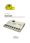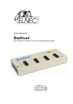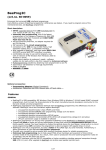
1
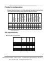
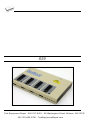
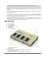
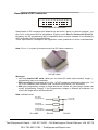
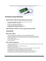
User's Manual for 859 Fast universal 4x 48-pindrive concurrent multiprogramming system with ISP capability 99 Washington Street Melrose, MA 02176 Phone 781-665-1400 Toll Free 1-800-517-8431 Visit us at www.TestEquipmentDepot.com This document is copyrighted by B+K Precision, Yorba Linda - California. All rights reserved. This document or any part of it may not be copied, reproduced or translated in any form or in any way without the prior written permission of B+K Precision. The control program is copyright B+K Precision, Yorba Linda - California. The control program or any part of it may not be analyzed, disassembled or modified in any form, on any medium, for any purpose. Information provided in this manual is intended to be accurate at the moment of release, but we continuously improve all our products. B+K Precision assumes no responsibility for misuse of this manual. B+K Precision reserves the right to make changes or improvements to the product described in this manual at any time without notice. This manual contains names of companies, software products, etc., which may be trademarks of their respective owners. B+K Precision respects those trademarks. COPYRIGHT 1997 - 2007 B+K Precision Corporation How to use this manual This manual explains how to install the control program and how to use your programmer. It is assumed that the user has some experience with PCs and installation of software. Once you have installed the control program we recommend you consult the context sensitive HELP within the control program rather than the printed User's Manual. Revisions are implemented in the context sensitive help before the printed User’s Manual. Dear customer, thank you for purchasing one of the B+K PRECISION programmer. Conventions used in the manual References to the control program functions are in bold, e.g. Load, File, Device, etc. References to control keys are written in brackets <>, e.g. <F1>. Terminology used in the manual: Device ZIF socket Buffer Printer port USB port HEX data format any kind of programmable integrated circuits or programmable devices Zero Insertion Force socket used for insertion of target device part of memory or disk, used for temporary data storage type of PC port (parallel), which is primarily dedicated for printer connection. type of PC port (serial), which is dedicated for connecting portable and peripheral devices. format of data file, which may be read with standard text viewers; e.g. byte 5AH is stored as characters '5' and 'A', which mean bytes 35H and 41H. One line of this HEX file (one record) contains start address and data bytes. All records are secured with checksum. Products configuration ISP cable ZIF anti-dust cover software CD User’s manual on CD registration card shipping case - 1x 1x 4x 4x * - 844USB - - - 848A - - - - - - ISP diagnostic PO D LPT c able diagnostic POD USB cable - internal power supply programmer external power supply Before installing and using your programmer, please carefully check that your package includes all next mentioned parts. If you find any discrepancy with respective parts list and/or if any of these items are damaged, please contact your distributor immediately. Package included 859 866B * optional accessories PC requirements USB 1.1 LPT CDROM 848A 866B 859 OS - Windows CPU RAM [MB] free disk space [MB] USB 2.0 high speed 844USB Minimal PC requirements 2000 P4 256 150 98 PIII 128 60 98 PIII 128 60 95 PII 64 60 Test Equipment Depot - 800.517.8431 - 99 Washington Street Melrose, MA 02176 FAX 781.665.0780 - TestEquipmentDepot.com XP Core2Duo 1000 250 XP P4 512 150 XP P4 512 150 XP P4 256 150 848A 866B CDROM 859 OS - Windows CPU RAM [MB] free disk space [MB] USB 2.0 high speed LPT IEEE1284 844USB Recommended PC requirements These PC requirements are valid for 2.34/01.2007 version of control program for programmers. For other version see Help / About control program. Note: For convenience, we suggest that you use a supplementary multi I/O card to provide an additional printer port (LPT2 for example), in order to avoid sharing the same LPT port between printer and programmer. Free disk space requirements depends also on used IC device size. For large devices the required free space on disk will be approximately 60MB + Device size. Free additional services: Why is it important to use the latest version of the control program? Semiconductor manufacturers continuously introduce new devices with new package types, manufactured by new technologies in order to support the need for flexibility, quality and speed in product design and manufacturing. To keep pace and to keep you up-to-date, we usually implement more than 5000 new devices into the control program within a year. Furthermore, a typical programmable device undergoes several changes during its lifetime in an effort to maintain or to improve its technical characteristics and process yields. These changes often impact with the programming algorithms, which need to be upgraded (the programming algorithm is a set of instructions that tells the programmer how to program data into a particular target device). Using the newest algorithms in the programming process is the key to obtaining high quality results. In many cases, while the older algorithm will still program the device, they may not provide the level of data retention that would be possible with an optimal algorithm. Failure to not use the most current algorithm can decrease your programming yields (more improper programmed target devices), and may often increase programming times, or even affect the long term reliability of the programmed device. We are making mistakes too ... . Our commitment is to implement support for these new or modified parts before or as soon as possible after their release, so that you can be sure that you are using latest and/or optimal programming algorithms that were created for this new device. free technical support (phone/fax/e -mail). free lifetime software update via Web site. We also offer the following new services in our customer support program: Keep-Current and AlgOR. Keep-Current is a service by which B+K PRECISION ships to you the latest version of the control program for programmer and the updated user documentation. A Keep-Current service is your hassle-free guarantee that you always have access to the latest software and documentation, at minimal cost. AlgOR (Algorithm On Request) service allows you to receive from B+K PRECISION software support for programming devices not yet available in the current device list. Installing programmer hardware connect the USB (or LPT) port of programmer to a USB (or printer) port of PC using supplied cable connect the connector of the power supply adapter to the programmer or turn on programmer by switch Installing the programmer software Run the installation program from the CD (Setup.exe) and follow the on-screen instructions. Please, for latest information about the programmer hardware and software see www.bkprecision.com. Run the control program Double click on After start, control program Pg4uw automatically scans all existing ports and searches for some connected B+K PRECISION programmer. Program Pg4uw is common for some B+K PRECISION's programmers, hence Pg4uw will try to find all supported programmers. Menu File is used for source files manipulation, settings and viewing directory, changes drives, changes start and finish address of buffer for loading and saving files and loading and saving projects. Menu Buffer is used for buffer manipulation, block operation, filling a part of buffer with string, erasing, checksum and of course editing and viewing with other items (find and replace string, printing...). Menu Device is used for a work with selected programmable device: select, read, blank check, program, verify, erase and setting of programming process, serialization and associated file control. Menu Programmer is used for work with programmer. Menu Options is used to view and change various d efault settings. Menu Help is used for view supported devices and programmers and information about program version. Programming a device 1. select device: click on 2. load data into buffer: a) from file: click on b) from device: insert device to ZIF and click on 3. insert target device to ZIF 4. check, if the device is blank: click on 5. program device: click on 6. additional verify of device: click on 859 Test Equipment Depot - 800.517.8431 - 99 Washington Street Melrose, MA 02176 FAX 781.665.0780 - TestEquipmentDepot.com Introduction 859 is extremely fast universal 4x 48-pindrive concurrent multiprogramming system designed for high volume production programming with minimal operator effort. The chips are programmed at near theoretical maximum programming speed. 859 consists of four independent isolated universal programming modules, based on the 866B programmer hardware. Therefore the sockets can run asynchronously (concurrent programming mode). Each programming module starts programming at the moment the chip is detected to be inserted in the socket properly - independently on the status of other programming modules. It result three programming modules works while you replace the programmed chip at the fourth. Modular construction of hardware - the programming modules works independently - allows for continuing operation when a part of the circuit becomes inoperable. It also makes service quick and easy. Hands-free operation: asynchronous and concurrent operation allows a chip to begin programming immediately upon insertion of a chip. The operator merely removes the finished chip and inserts a new chip. Operator training is therefore minimized.. 859 supports all kinds of types and silicon technologies of today and tomorrow programmable devices without family-specific module. You can be sure the next devices support require the software update and (if necessary) simple package converter (programming adapter), therefore the ownership cost are minimized. Using built-in in-circuit serial programming (ISP) connector, the programmer is able to program ISP capable chips in circuit. 859 provides very competitive price coupled with excellent hardware design for reliable programming. It has probably best "value for money" programmer in this class. 859 provides very fast programming due to high-speed FPGA driven hardware and execution of time-critical routines inside of the programmer. At least fast than competitors in this category, for many chips much faster than most competitors. As a result, when used in production this programmer waits for an operator, and not the other way round. 859 interfaces with the IBM PC/compatible, portable or desktop personal computers through USB (2.0) port. 859 provides a banana jack for ESD wrist straps connection to easy-to-implement the ESD protection control and also other banana jack for earth wire. FPGA based totally reconfigurable 48 powerful TTL pindrivers provide H/L/pull_up/pull_down and read capability for each pin of socket. Advanced pindrivers incorporate high-quality highspeed circuitry to deliver signals without overshoot or ground bounce for all supported devices. Pin drivers operate down to 1.8V so you'll be ready to program the full range of today's advanced low-voltage devices. 859 performs on each programming module device insertion test (wrong or backward position) and contact check (poor contact pin-to-socket) before it programs each device. These capabilities, supported by overcurrent protection and signature-byte check help prevent chip damage due to operator error. 859 has the selftest capability, which allows run diagnostic part of software to thoroughly check the health of the each programming module. 859 has a built-in protection circuits for eliminate damage of programmer and/or programmed device due to environment or operator failure. All ZIF socket pins of 859 programmer are protected against ESD up to 15kV. 859 performs programming verification at the marginal level of supply voltage, which, obviously, improves programming yield, and guarantees long data retention. Various socket converters are available to handle device in PLCC, SOIC, PSOP, SSOP, TSOP, TSSOP, TQFP, QFN (MLF), SDIP, BGA and other packages. 859 programmer is driven by an easy-to-use control program with pull-down menu, hot keys and on-line help. Selecting of device is performed by its class, by manufacturer or simply by typing a fragment of vendor name and/or part number. Standard device-related commands (read, blank check, program, verify, erase) are boosted by some test functions (insertion test, signature-byte check), and some special functions (autoincrement, production mode - start immediately after insertion of chip into socket). All known data formats are supported. Automatic file format detection and conversion during load of file. The rich-featured autoincrement function enables to assign individual serial numbers to each programmed device - or simply increments a serial number, or the function enables to read serial numbers or any programmed device identification signatures from a file. The software also provides a many information about programmed device. As a special, the drawings of all available packages, explanation of chip labeling (the meaning of prefixes and suffixes at the chips) for each supported chip are provided. The software provide a full information for ISP implementation: Description of ISP connector pins for currently selected chip, recommended target design around in-circuit programmed chip and other necessary information. The remote control feature allows to be Pg4uw software flow controlled by other application – either using .BAT file commands or using DLL file. DLL file, examples (C/PAS/VBASIC/.NET) and manual are part of standard software delivery. Jam files of JEDEC standard JESD-71 are interpreted by Jam Player. Jam files are generated by design software which is provided by manufacturer of respective programmable device. Chips are programmer in-ZIF or through ISP connector (IEEE 1149.1 Joint Test Action Group (JTAG) interface). VME files are interpreted by VME Player. VME file is a compressed binary variation of SVF file and contains high-level IEEE 1149.1 bus operations. VME files are generated by design software which is provided by manufacturer of respective programmable device. Chips are programmer in-ZIF or through ISP connector (IEEE 1149.1 Joint Test Action Group (JTAG) interface). Multiple devices are possible to program and test via JTAG chain: JTAG chain (ISP-Jam) or JTAG chain (ISP-VME). It is important to remember that in most cases new devices require only a software update due to the 859 is truly universal programmer. With our prompt service you can have new devices can be added to the current list within hours! Advanced design including protection circuits, original brand components and careful manufacturing and burning allows us to provide a one-year warranty on parts and labor for the 859 (limited 25,000-cycle warranty on ZIF socket). 859 elements 1) 2) 3) 4) 5) 6) 48 pin ZIF socket work result LEDs power/sleep LED of site YES! Button ISP connector LED indicator power 7) 8) 9) 10) 11) power supply connector power switch GND connector and connector for ESD wrist strap connection temperature controlled fans type B USB c onnector for PC 859 communication cable Manipulation with the programmed device After selection of desired device for your work, you can insert it into the open ZIF socket (the lever is up) and close socket (the lever is down). The correct orientation of the programmed device in ZIF socket is shown on the picture near ZIF socket on the programmer's cover. The programmed device is necessary to insert into the socket also to remove from the socket when LED BUSY light off. Note: Programmer's protection electronics protect the target device and the programmer itself against either short or long-term power failures and, partly, also against a PC failure. However, it is not possible to grant the integrity of the target device due to incorrect, userselected programming parameters. Target device may be not destroyed by forced interruption of the control program (reset or switch-off PC), by removing the physical connection to the programmer, but the content of actually programmed cell may remains undefined. Don't unplug the target device from the ZIF socket during work with devices (LED BUSY shine). In-system serial programming by 859 Optimized advanced pindriver deliver programming performance without overshoot or ground bounce for all device technologies. Pin drivers operate down to 1.8V so you'll be ready to program the full range of today's advanced low- voltage devices. The ISP programming solution performs programming verification at the marginal level of supply voltage, which, obviously, improves programming yield, and guarantees long data retention. The ISP programming solution provides also the power supply for the target system. This ISP programming solution provides very competitive price but excellent hardware design for reliable programming. The software provide full information for ISP implementation: Description of ISP connector pins for currently selected chip, recommended target design around in-circuit programmed chip and other necessary information. For general definition, recommendation and direction about ISP see section Common notes / ISP please. Description of ISP connector 2 4 6 8 10 12 14 16 18 20 1 3 5 7 9 11 13 15 17 19 Front view at ISP connector. Specification of ISP connector pins depends on the device, which you want to program. You can find it in the control SW for programmer (Pg4uw), menu Device / Device Info (Ctrl+F1). Be aware, the ISP programming way of respective device must be selected. It is indicated by (ISP) suffix after name of selected device. These specifications correspond with application notes published of device manufacturers. Note: Pin no. 1 is signed by triangle scratch on ISP cable connectors. 859 ISP cable Warnings: Use only attached ISP cable. When you use other ISP cable (other material, length…), programming may occur unreliable. 859 can supply programmed device (pin 1 of ISP connector) and target system (pin 19, 20 of ISP connector) with limitation (see Technical specification / ISP connector). 859 apply programming voltage to target device and checks his value (target system can modify programming voltage). If the programming voltage is different as expected, no action with target device will be executed. Note: H/L/read driver R1 H/L driver in programmer pin of ISP connector R2 read driver in programmer R3 PU/PD driver in programmer R1=180R R2=1k3 R3=22k Test Equipment Depot - 800.517.8431 - 99 Washington Street Melrose, MA 02176 FAX 781.665.0780 - TestEquipmentDepot.com Selftest and calibration check If you feel that your programmer does not react according to your expectation, please run the programmer (ISP connector) selftest using Diagnostic POD (Diagnostic POD for ISP connectors #2), enclosed with the standard delivery package. Selftest of programmer Insert 48 pins diagnostic POD - type I into ZIF socket of the programmer. 48 pins diagnostic POD - type I must be inserted as 48 pins device. Run selftest of programmer in PG4UW (Programmer / Selftest plus). Selftest of ISP connector Insert Diagnostic POD for ISP connectors #2 into ZIF socket of the programmer. Diagnostic POD for ISP connectors #2 must be inserted as 48 pins device. Interconnect 20 pins connector of Diagnostic POD for ISP connectors #2 with an ISP connector of the programmer with an ISP cable, included in delivery programmer package. Be sure that pins are interconnected properly (i.e. 1-1, 2-2, ..., 20-20). Run selftest of ISP connector in PG4UW (Programmer / Selftest ISP connector…). Calibration test For optimal results with programmer we recommend you also undertake every 6 months an extended test to check the calibration using 48 Pins Calibration test POD, Type I (optional accessories, ord.no. 70-0438). Insert 48 Pins Calibration test POD, Type I into ZIF socket of the programmer. 48 Pins Calibration test POD, Type I must be inserted as 48 pins device. Run calibration test of programmer in PG4UW (Programmer / Calibration test). Technical specification Specification (859 multiprogramming system) 4x universal programming module (4x 48-pin DIL ZIF sockets) operation result LEDs, LED power USB 2.0 high-speed compatible port line power input 100-240VAC/60W max. banana jack for ESD wrist straps connection banana jack for connection to ground Specification (valid for each programming module) HARDWARE Base unit, DACs USB 2.0 high-speed compatible port, up to 480 Mbit/s transfer rate on-board intelligence: powerful microprocessor and FPGA based state machine three D/A converters for VCCP, VPP1, and VPP2, controllable rise and fall time VCCP range 0..8V/1A VPP1, VPP2 range 0..26V/1A selftest capability ZIF sockets, pindriver 48-pin DIL ZIF (Zero Insertion Force) socket accepts both 300/600 mil devices up to 48-pin pindrivers: 48 universal VCCP/VPP1/VPP2 can be connected to each pin perfect ground for each pin FPGA based TTL driver provides H, L, CLK, pull-up, pull-down on all pindriver pins analog pindriver output level selectable from 1.8 V up to 26V current limitation, overcurrent shutdown, power failure shutdown ESD protection on each pin of socket (IEC1000-4-2: 15kV air, 8kV contact) continuity test: each pin is tested before every programming operation ISP connector 20-pin male type with missinsertion lock 6 TTL pindrivers, provides H, L, CLK, pull-up, pull-down; level H selectable from 1.8V up to 5V to handle all (low-voltage including) devices. 1x VCCP voltage (range 2V..7V/100mA) programmed chip voltage (VCCP) with both source/sink capability and voltage sense 1x VPP voltage (range 2V..25V/50mA) target system supply voltage (range 2V..6V/250mA) ESD protection on each pin of ISP connector (IEC1000 -4-2: 15kV air, 8kV contact) two output signals, which indicate state of work result = LED OK and LED Error (active level: min 1.8V) input signal, switch YES! equivalent (active level: max 0.8V) DEVICE SUPPORT Programmer, in ZIF socket EPROM: NMOS/CMOS, 27xxx and 27Cxxx series, with 8/16 bit data width, full support for LV series EEPROM: NMOS/CMOS, 28xxx, 28Cxxx, 27EExxx series, with 8/16 bit data width Flash EPROM: 28Fxxx, 29Cxxx, 29Fxxx, 29BVxxx, 29LVxxx, 29Wxxx, 49Fxxx series, from 256Kbit to 1Gbit, with 8/16 bit data width, full support for LV series Serial E(E)PROM: 24Cxxx, 24Fxxx, 25Cxxx, 45Dxxx, 59Cxxx, 25Fxxx, 25Pxxx, 85xxx, 93Cxxx, NVM3060, MDAxxx series, full support for LV series Configuration (EE)PROM: XCFxxx, XC17xxxx, XC18Vxxx, EPCxxx, AT17xxx, 37LVxx 1-Wire E(E)PROM: DS1xxx, DS2xxx PROM: AMD, Harris, National, Philips/Signetics, Tesla, TI NV RAM: Dallas DSxxx, SGS/Inmos MKxxx, SIMTEK STKxxx, XICOR 2xxx, ZMD U63x series PLD: Altera: MAX 3000A, MAX 7000A, MAX 7000B, MAX 7000S, MAX7000AE, MAX II PLD: Lattice: ispGAL22V10x, ispLSI1xxx, ispLSI1xxxEA, ispLSI2xxx, ispLSI2xxxA, ispLSI2xxxE, ispLSI2xxxV, ispLSI2xxxVE, ispLSI2xxxVL, LC4xxxB/C/V/ZC, M4-xx/xx, M4A3-xx/xx, M4A5-xx/xx, M4LV-xx/xx PLD: Xilinx: XC9500, XC9500XL, XC9500XV, CoolRunner XPLA3, CoolRunner -II other PLD: SPLD/CPLD series: AMI, Atmel, AMD-Vantis, Gould, Cypress, ICT, Lattice, NS, Philips, STM, VLSI, TI Microcontrollers 48 series: 87x41, 87x42, 87x48, 87x49, 87x50 series Microcontrollers 51 series: 87xx, 87Cxxx, 87LVxx, 89Cxxx, 89Sxxx, 89LVxxx, all manufacturers, Philips LPC series Microcontrollers Intel 196 series: 87C196 KB/KC/KD/KT/KR/... Microcontrollers Atmel AVR: AT90Sxxxx, ATtiny, ATmega series Microcontrollers Cypress: CY7Cxxxxx, CY8Cxxxxx Microcontrollers ELAN: EM78Pxxx Microcontrollers MDT 1xxx and 2xxx series Microcontrollers Microchip PICmicro: PIC10xxx, PIC12xxx, PIC16xxx, PIC17Cxxx, PIC18xxx, PIC24xxx, dsPIC series Microcontrollers Motorola (Freescale): 68HC05, 68HC08, 68HC11, HCS08, HCS12 series Microcontrollers Myson MTV2xx, 3xx, 4xx and 5xx series Microcontrollers National: COP8xxx series Microcontrollers NEC: uPD78Fxxx series Microcontrollers Novatek: NT68xxx series Microcontrollers Scenix (Ubicom): SXxxx series Microcontrollers SGS-Thomson: ST6xx, ST7xx, ST10xx, STR7xx series Microcontrollers TI: MSP430 and MSC121x series Microcontrollers ZILOG: Z86/Z89xxx and Z8xxx series Microcontrollers other: EM Microelectronic, Fujitsu, Goal Semiconductor, Hitachi, Holtek, Princeton, Macronix, Winbond, Infineon(Siemens), Samsung, Toshiba, ... I.C. Tester TTL type: 54,74 S/LS/ALS/H/HC/HCT series CMOS type: 4000, 4500 series static RAM: 6116.. 624000 user definable test pattern generation Programmer, through ISP connector Serial E(E)PROM: IIC series, MW series, SPI series, KEELOQ series, serial data Flash, PLD configuration memories Microcontrollers Atmel: AT89Sxxx, AT90Sxxxx, ATtiny, ATmega series Microcontrollers Cypress: CY8C2xxxx Microcontrollers Elan: EM78Pxxx, EM6xxx series Microcontrollers EM Microelectronic: 4 and 8 bit series Microcontrollers Microchip PICmicro: PIC10xxx, PIC12xxx, PIC16xxx, PIC17xxx, PIC18xxx, PIC24xxx, dsPIC series Microcontrollers Motorola/Freescale: HC11 series, HC908 series (both 5-wire, All-wire), HCS08, HCS12 Microcontrollers NEC: uPD7xxx series Microcontrollers Philips: LPC2xxx series, LPC series, 89xxx series Microcontrollers Scenix (Ubicom): SXxxx series Microcontrollers TI: MSP430 (both JTAG and BSL series), MSC12xxx series PLD: Lattice: ispGAL22xV10x, ispLSI1xxxEA, ispLSI2xxxE, ispLSI2xxxV, ispLSI2xxxVE, ispLSI2xxxVL, M4-xx/xx, M4LV-xx/xx, M4A3-xx/xx, M4A5-xx/xx, LC4xxxB/C/V/ZC Various PLD (also by JAM player/JTAG support): Altera: MAX 3000A, MAX 7000A, MAX 7000B, MAX 7000S, MAX 9000, MAX II Xilinx: XC9500, XC9500XL, XC9500XV, CoolRunner XPLA3, CoolRunner-II Package support support all devices in DIP with default socket package support includes DIP, SDIP, PLCC, JLCC, SOIC, SOP, PSOP, SSOP, TSOP, TSOPII, TSSOP, QFP, PQFP, TQFP, VQFP, QFN (MLF), SON, BGA, EBGA, FBGA, VFBGA, UBGA, FTBGA, LAP, CSP, SCSP etc. support devices in non-DIP packages up to 48 pins with universal adapters programmer is compatible with third-party adapters for non-DIP support Programming speed Device M50FW080 (parallel Flash) MX28F640C3BT (parallel Flash) K9F1G08U0M (parallel NAND Flash) AT45D081 (serial Flash) AT89C51RD2 (microcontroller) PIC18LF452 (microcontroller) Conditions: Size [bits] 100000Hx8 (8 Mega) 400000Hx16 (64 Mega) 8400000Hx8 (1 Giga) 108000Hx8 (16 Mega) 10000Hx8 4000Hx16 Operation programming and verify programming and verify programming and verify programming and verify programming and verify programming and verify Time 22 sec 57 sec 239 sec 36 sec 15 sec 4 sec P4, 2.4GHz, 512MB RAM, USB2.0, Windows XP SOFTWARE Algorithms: only manufacturer approved or certified algorithms are used. Algorithm updates: software updates are available regularly, approx. every 4 weeks, free of charge (Internet download). OnDemand version of software is available for highly needed chips support and/or bugs fixes. Available nearly daily. Main features: revision history, session logging, on-line help, device and algorithm information Device operations standard: intelligent device selection by device type, manufacturer or typed fragment of part name automatic ID-based selection of EPROM/Flash EPROM blank check, read, verify program erase configuration and security bit program illegal bit test checksum interpret the Jam Standard Test and Programming Language (STAPL), JEDEC standard JESD-71 interpret the VME files compressed binary variation of SVF files security insertion test, reverse insertion check contact check ID byte check special production mode (automatic start immediately after device insertion) lot of serialization modes (more type of incremental modes, from-file mode, custom generator mode) statistic count-down mode Buffer operations view/edit, find/replace fill/copy, move, byte swap, word/dword split checksum (byte, word) print Test Equipment Depot - 800.517.8431 - 99 Washington Street Melrose, MA 02176 FAX 781.665.0780 - TestEquipmentDepot.com File load/save no download time because programmer is PC controlled automatic file type identification/recognition Supported file formats unformatted (raw) binary HEX: Intel, Intel EXT, Motorola S-record, MOS, Exormax, Tektronix, ASCII-SPACE-HEX, ASCII HEX Altera POF, JEDEC (ver. 3.0.A), e.g. from ABEL, CUPL, PALASM, TANGO PLD, OrCAD PLD, PLD Designer ISDATA, etc. JAM (JEDEC STAPL Format), JBC (Jam STAPL Byte Code), STAPL (STAPL File) JEDEC standard JESD-71 VME (ispVME file VME2.0/VME3.0) GENERAL supply voltage AC 100-240V, max. 1.2A, 50-60Hz power consumption max. 60W active dimensions 361x234x56 mm (14.2x9.2 x2.2 inch) weight (programmer) 3.5kg (7.7 lb) temperature 5°C ÷ 40°C (41°F ÷ 104°F) humidity 20%..80%, non condensing Visit us at www.TestEquipmentDepot.com