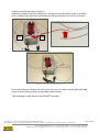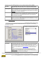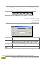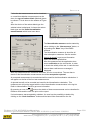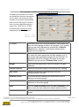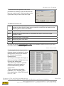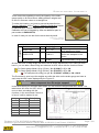
1
DABS – DATA ABSORPTOMETER SYSTEM Oil Absorption, OAN/COAN ASTM D2414 and D3493 Key Data Connects to PC via serial port or via LAN with optional ComServer Terminal fully dust proof, resistant to DBP, can be handled by operator wearing protective gloves Options: Mixing chamber cooling block, chamber extension funnel for testing of fluffy material Table model dimensions: 400 x 500 x 700 mm (WxDxH) - Weight: 60 kg Design Objectives Fits standard mixing chambers - handy access to chamber, safety cage opens fully for cleaning and filling, no hindering safety switch brackets Frequency inverter driven asynchronous motor for variable speed and smooth start Full burette control including variable debit speed Integrated DADS Oil Absorption Data System Due to continual product research and development, the information contained herein is subject to change without notification. Copyright © 2011 HITEC Luxembourg. The HITEC Luxembourg Logo is trademark of HITEC Luxembourg S.A., Luxembourg. Proprietary Notice The information contained herein is proprietary to the manufacturer, and any may not be used, reproduced, or disclosed to others except as specifically permitted in writing by its originators. The recipient of this information, by its retention and use, agrees to protect the product and information contained therein from loss, theft and compromise. Les informations contenues dans ce document sont la propriété du constructeur, aucune ne peut être reproduite ou divulguée à de tierces parties sans son accord écrit. Le receveur de ces informations, par sa conservation et son usage, s'engage à protéger le produit et les informations contenues contre la perte, le vol ou les altérations. Die in diesem Dokument enthaltenen Informationen sind Eigentum des Herstellers und dürfen nicht ohne ausdrückliche schriftliche Einwilligung des Erstellers benutzt, reproduziert oder anderen bekannt gemacht werden. Der Empfänger dieser Information willigt ein, wenn er diese behält oder verwendet, sie vor Verlust, Diebstahl und Gefährdung zu schützen. Document Details Document Type End User Manual File Name HTCA_003-DADS-UserManual.docx Version Date 01/05/2010 History of Change Author Date Comment S. LONTRO 09/04/2010 Copy from HITEC App. Help Content S. LONTRO 01/05/2010 Updated till HTCA 4.0.25 version File Name: HTCA_003-DADS-UserManual.docx Page 2/81 Document Type: End User Manual | Version date: 01/05/2010 | Last Printed: 15/02/2011 Hitec Luxembourg S.A. | 5, Rue de l’Église, L-1458 Luxembourg www.hitec.lu | [email protected] | Tel.: (+352) 49 84 78 - 1 | Fax. (+352) 401303 Table of Contents DABS – Data Absorptometer System ..................................................................................................... 1 Key Data.............................................................................................................................................. 1 Design Objectives ............................................................................................................................... 1 Proprietary Notice ................................................................................................................................... 2 Document Details .................................................................................................................................... 2 History of Change ............................................................................................................................... 2 Table of Contents ................................................................................................................................ 3 Table of Figures .................................................................................................................................. 5 Introduction.............................................................................................................................................. 6 Application Overview ............................................................................................................................... 6 DADS Terminal Overview ....................................................................................................................... 7 Absorptometer Overview..................................................................................................................... 8 HITEC Absorptometer, Type H (DABS) .......................................................................................... 8 Brabender Absorptometer, Type E ................................................................................................. 8 Brabender Absorptometer, Type B ................................................................................................. 8 Burettes Overview ............................................................................................................................... 9 Burette Modes ................................................................................................................................. 9 Supported Burette Types ................................................................................................................ 9 Terms and Definitions ........................................................................................................................... 10 ASTM Standards ............................................................................................................................... 10 TLS Measurement ............................................................................................................................. 11 TLS Modes .................................................................................................................................... 12 Normalization Measurement ............................................................................................................. 12 DADS Measurement Concept ........................................................................................................... 14 DABS & Burette Installation .................................................................................................................. 17 Equipment and Parts ......................................................................................................................... 17 Mains Supply ..................................................................................................................................... 18 Mains Supply Adjustment.............................................................................................................. 18 Fuses............................................................................................................................................. 18 Burette components .......................................................................................................................... 19 Mounting all Components ................................................................................................................. 19 Stand Rod & Tip Holder ................................................................................................................ 19 Connecting the Burette ................................................................................................................. 21 Starting on First Installation................................................................................................................... 22 Operating Buttons ................................................................................................................................. 23 DADS Terminal ................................................................................................................................. 23 DABS Front door ............................................................................................................................... 24 DADS Application User Manual ............................................................................................................ 25 Software Config ................................................................................................................................. 25 Main Window Sections ...................................................................................................................... 27 Parameters Section ....................................................................................................................... 28 Test results Section ....................................................................................................................... 30 Configuration Section .................................................................................................................... 31 Graph Section ............................................................................................................................... 31 Terminal Section ........................................................................................................................... 32 File Name: HTCA_003-DADS-UserManual.docx Page 3/81 Document Type: End User Manual | Version date: 01/05/2010 | Last Printed: 15/02/2011 Hitec Luxembourg S.A. | 5, Rue de l’Église, L-1458 Luxembourg www.hitec.lu | [email protected] | Tel.: (+352) 49 84 78 - 1 | Fax. (+352) 401303 Application Control Section ........................................................................................................... 33 Menus Description ............................................................................................................................ 33 Menu File....................................................................................................................................... 33 Print Setup ................................................................................................................................. 33 Print ........................................................................................................................................... 34 Export ........................................................................................................................................ 35 Exit ............................................................................................................................................ 35 Menu Configuration ....................................................................................................................... 36 Chamber.................................................................................................................................... 36 Cleaning .................................................................................................................................... 37 Burette Mode ............................................................................................................................. 37 Sampling Rate ........................................................................................................................... 37 Language .................................................................................................................................. 37 Menu Maintenance ........................................................................................................................ 38 TLS ............................................................................................................................................ 38 Normalization ............................................................................................................................ 43 Attenuation ................................................................................................................................ 48 Burette Debit ............................................................................................................................. 50 Torque Calibration ..................................................................................................................... 52 Encoder Zero............................................................................................................................. 54 Backup Config ........................................................................................................................... 55 Pre-polish .................................................................................................................................. 55 Burette Purge ............................................................................................................................ 56 Action Log ................................................................................................................................. 56 Menu Tools.................................................................................................................................... 57 Retrieve ..................................................................................................................................... 57 Properties .................................................................................................................................. 57 Hitec Config ............................................................................................................................... 59 Quality Editor ............................................................................................................................. 59 Test List Editor .......................................................................................................................... 59 Master Curve Editor .................................................................................................................. 59 Menu Help ..................................................................................................................................... 59 Contents .................................................................................................................................... 59 DADS description ...................................................................................................................... 60 About ......................................................................................................................................... 60 How to do a test? .............................................................................................................................. 61 Normal Absorption Test Procedures ............................................................................................. 61 Default test procedure ............................................................................................................... 62 Quality list measurement procedure ......................................................................................... 63 Test list measurement procedure .............................................................................................. 64 TLS and Normalization Test.......................................................................................................... 65 Abort a Test ................................................................................................................................... 65 Start Condition of a Measurement Recording ............................................................................... 66 End Condition of a Measurement Recording ................................................................................ 66 Polynomial and Test Results......................................................................................................... 66 Validity of Test Sequence (Absorptometer Type H only) ............................................................. 66 File Name: HTCA_003-DADS-UserManual.docx Page 4/81 Document Type: End User Manual | Version date: 01/05/2010 | Last Printed: 15/02/2011 Hitec Luxembourg S.A. | 5, Rue de l’Église, L-1458 Luxembourg www.hitec.lu | [email protected] | Tel.: (+352) 49 84 78 - 1 | Fax. (+352) 401303 Maintenance .......................................................................................................................................... 67 Cleaning Chamber ............................................................................................................................ 67 Changing Drive ................................................................................................................................. 68 Local Mode ........................................................................................................................................ 69 Run Motor on Local Mode ................................................................................................................. 69 Strain-gauge (Torque) Calibration .................................................................................................... 70 Strain-gauge Settings .................................................................................................................... 70 Strain-gauge Linearity ................................................................................................................... 71 Temperature Calibration ................................................................................................................... 73 Other Accessories ................................................................................................................................. 74 Temperature Sensor ......................................................................................................................... 74 Chamber Extension Funnel............................................................................................................... 74 Cooling Block with Quick Couplings ................................................................................................. 74 Troubleshooting .................................................................................................................................... 75 Unable to Open the Port ................................................................................................................... 75 Communication Time out .................................................................................................................. 75 Computer & Mouse reacts Strangely ................................................................................................ 76 DADS Test Program ......................................................................................................................... 76 FAQ / Frequently Asked Questions ...................................................................................................... 77 Contact for Help .................................................................................................................................... 78 About HITEC Luxembourg .................................................................................................................... 78 Glossary ................................................................................................................................................ 79 Table of Figures Figure 1 – DADS Terminal ...................................................................................................................... 7 Figure 2 – ASTM for Standard Reference Blacks ................................................................................. 12 Figure 3 – Connecting Burette Hoses ................................................................................................... 20 Figure 4 – DADS Configuration window ............................................................................................... 26 Figure 5 – Slope option ......................................................................................................................... 32 Figure 6 – Print Preview ........................................................................................................................ 34 Figure 7 – TLS in Target Value Mode ................................................................................................... 38 Figure 8 – TLS in 70% mode ................................................................................................................ 40 Figure 9 – TLS in manual mode ............................................................................................................ 41 Figure 10 – TLS Trend Graph ............................................................................................................... 42 Figure 11 – Normalisation Dates Table ................................................................................................ 43 Figure 12 – Normalization Trend choice window .................................................................................. 44 Figure 13 – Normalization Trend Graph ............................................................................................... 45 Figure 14 – Normalization measure selection ....................................................................................... 47 Figure 15 – Torque Calibration window ............................................................................................... 52 Figure 16 – Test Properties Window ..................................................................................................... 57 Figure 17 – Torque Calibration Kit ....................................................................................................... 71 Figure 18 – Temperature Calibration Kit ............................................................................................... 73 File Name: HTCA_003-DADS-UserManual.docx Page 5/81 Document Type: End User Manual | Version date: 01/05/2010 | Last Printed: 15/02/2011 Hitec Luxembourg S.A. | 5, Rue de l’Église, L-1458 Luxembourg www.hitec.lu | [email protected] | Tel.: (+352) 49 84 78 - 1 | Fax. (+352) 401303 Introduction This manual is written in order to let operate know how to work with a DABS, the HITEC Absorptometer Type H, but the most part of its content is based on the Hitec DADS application. The DADS application was developed to operate the DADS terminal (the upper box of the DABS) which was used as the data acquisition system connected to the Brabender Absorptometers Type E and B. Today the DADS terminal production as a single part is stopping and is produced only for replacement or troubleshooting. But this document describes the application function for this terminal. Note: Before you start working with the DABS tester (or DADS terminal), please read the sections DABS & Burette Installation Starting on First Installation, DADS Measurement Concept How to do a test? Safety note for the HITEC type H Absorptometer (DABS) The protection door must stay installed and has to be closed during a measurement. Application Overview The carbon black absorption test is used in the rubber and carbon black production industry. The absorption test determines the quantity of liquid a carbon black sample is able to absorb. The HITEC DADS application provides an automatic tool to execute absorption tests and record the data resulting. The principle of an absorption test is the following. A certain amount of carbon black is introduced into a defined mixing chamber. During the measurement the carbon black in the chamber is mixed, and liquid is added to it. A mixture is created developing a certain resistance to the mixing chamber rotor blades. This resistance can be defined by torque. The DADS application records the torque vs. quantity of liquid added and terminates the test in case certain conditions are fulfilled. See also the section How to do a test? for further information on the absorption measurement. As liquid n-Dibutyl Phthalate is used. This one will be called DBP in the current document. Other liquids could be used in the future, depending on the specifications. The DADS application measurements and operations are based on ASTM standards. Refer to ASTM Standards for further information on this topic. During the absorption test the raw curve torque vs. liquid quantity is recorded. After the test, a significant part of the curve is determined and a 3rd order polynomial is calculated, which has proven to be for carbon black a very good fit to the raw curve. All the calculations and test results are obtained with this polynomial. File Name: HTCA_003-DADS-UserManual.docx Page 6/81 Document Type: End User Manual | Version date: 01/05/2010 | Last Printed: 15/02/2011 Hitec Luxembourg S.A. | 5, Rue de l’Église, L-1458 Luxembourg www.hitec.lu | [email protected] | Tel.: (+352) 49 84 78 - 1 | Fax. (+352) 401303 DADS Terminal Overview We call DADS the Data Absorption Data system. This is a terminal which can be connected to different Absorption base units. Following is shown a picture of the DADS terminal. Figure 1 – DADS Terminal By using the HITEC application software package and this terminal connected to the base units, provides an extended control and monitoring system for absorption tests. Without the application the terminal is not able to run absorption tests. The following base units are supported: HITEC Absorptometer, Type H (DABS) Brabender Absorptometer, Type E Brabender Absorptometer, Type B The DADS terminal can be connected to different burette types. Refer to the section Burettes Overview for further information. Here after you will find an overview of the DADS terminal versions and which functionality they include. Terminal \ supports Brabender type E Brabender type B DADS version 1.0 DADS version 2.1 HITEC type H - Pulse mode burette (variable debit, full control) - Variable rotor Temperature speed (type measure H only) - - - DADS version 2.2 File Name: HTCA_003-DADS-UserManual.docx Page 7/81 Document Type: End User Manual | Version date: 01/05/2010 | Last Printed: 15/02/2011 Hitec Luxembourg S.A. | 5, Rue de l’Église, L-1458 Luxembourg www.hitec.lu | [email protected] | Tel.: (+352) 49 84 78 - 1 | Fax. (+352) 401303 Absorptometer Overview Different Absorptometers base units can be connected to the HITEC DADS terminal. Hereafter you will see the DADS terminal connected to different base units. HITEC Absorptometer, Type H (DABS) Brabender Absorptometer, Type E Brabender Absorptometer, Type B File Name: HTCA_003-DADS-UserManual.docx Page 8/81 Document Type: End User Manual | Version date: 01/05/2010 | Last Printed: 15/02/2011 Hitec Luxembourg S.A. | 5, Rue de l’Église, L-1458 Luxembourg www.hitec.lu | [email protected] | Tel.: (+352) 49 84 78 - 1 | Fax. (+352) 401303 Burettes Overview Burette Modes The HITEC application is able to work in different burette modes, depending on the requirements and/or possibilities of the burette and the DADS terminal. Refer to Burette Mode in Hitec Config manual for further information. The burette itself and the cable between the DADS terminal and the burette determine the mode which can be supported. The DADS terminal version 1.0 is not able to support the PULSE burette mode. The DADS terminal, with version greater than 2.0 supports all burette modes. Supported Burette Types The following burette types are supported, and tested in the PULSE mode. Brand Model Burette resolution (pulses / 50 ml) Remark Schott T 90/50 10 000 Equivalent to Brabender burette Schott Titronic Universal 8 000 Requires special EPROM. Metrohm Dosimat 685 10 000 Metrohm Dosimat 765 10 000 Metrohm Dosimat 865 10 000 The burette resolution can be set in the DADS Setup of the HITEC Config application. Other burettes with a closing contact reset input can be used in the burette RESET mode, supported by DADS terminals. Other burette with 5VDC control inputs for reset and pulse fill can possibly also be interfaced. For further information contact your HITEC products distributor Remarks: The fill time of the burette should be set to 90 seconds. Make sure all tube connections are tight. If this is not the case air could be sucked in and the measurement would be falsified. At least one burette purge should be done every morning before the measurements are started. This is done to eliminate the air inside of the burette cylinder and hoses. Use PTFE seals for the burette hoses as rubber is not necessarily resistant to DBP. Keep the burette hoses short. Long tubes can cause vacuum during refill and thus air bubbles being sucked into the system. File Name: HTCA_003-DADS-UserManual.docx Page 9/81 Document Type: End User Manual | Version date: 01/05/2010 | Last Printed: 15/02/2011 Hitec Luxembourg S.A. | 5, Rue de l’Église, L-1458 Luxembourg www.hitec.lu | [email protected] | Tel.: (+352) 49 84 78 - 1 | Fax. (+352) 401303 Terms and Definitions Different terms are used in the absorption test area. In the following sections some important terms are explained. ASTM Standards TLS Measurement Normalization Measurement DADS Measurement Concept ASTM Standards The DADS application supports the following ASTM standards. D 2414 Standard Test Method for Carbon Black - n-Dibutyl Phthalate Absorption Number. D 3493 Standard Test Method for Carbon Black - n-Dibutyl Phthalate Absorption Number of Compressed Sample. D 3324 Standard Practice for Carbon Black - Improving Test Reproducibility using ASTM Reference Blacks A new release of the ASTM 2414 has been balloted in December 1999. This splits the existing D 2414 in three methods. Procedure A End-point at fixed torque level This "classical" method is well suitable for hard blacks but often leads to problems when low-torque soft blacks are to be tested. Adjust the torque limit switch or indicator set point in such way that the SRB F-5 gives a value of 129.5 ± 1.5 cm3 / 100g. This method will be called Proc. A or ASTM method in the current document. The result will be called Proc. A or ASTM result. Procedure B End-point at 70% of the maximum torque Certain soft blacks and thermal blacks may fail to give an end-point due to insufficient torque level. Therefore the preferred method for testing soft blacks is to record the torque curve using a pen-recorder or a data acquisition system and to read the end-point at 70% of the maximum of the curve. Set the torque limit switch or the indicator set point to full scale in order to disable the automatic shut-off of the Absorptometer. The method and test results are called Proc. B. The percentage has to be defined in the HITEC Config application on the DADS Setup. The default value is 70% as defined in ASTM D2414 File Name: HTCA_003-DADS-UserManual.docx Page 10/81 Document Type: End User Manual | Version date: 01/05/2010 | Last Printed: 15/02/2011 Hitec Luxembourg S.A. | 5, Rue de l’Église, L-1458 Luxembourg www.hitec.lu | [email protected] | Tel.: (+352) 49 84 78 - 1 | Fax. (+352) 401303 Procedure C End-point at a fixed, but reduced torque level If low-torque blacks are to be tested and no recording system is available, it is recommended to reduce the setting of the torque limit switch or the indicator set point such that the SRB F-5 gives a result of 127.0 ± 1.0 cm3 / 100 g. This method can be simulated just by redoing the TLS measurements with the reduced target value. This is done in the HITEC Config application, in the DADS Setup. This would only be useful if data need to be correlated with measurements from other Absorptometer without data system. The HITEC DADS application supports the three test methods of this new method. Refer also to the ASTM homepage, to get further info on ASTM standards. TLS Measurement The following graph shows the TLS measurement (target value mode) of a F5 carbon black type. The target value is 129.5 ml/100g. Also refer to TLS Modes to get more information on the different modes the DADS can work with. File Name: HTCA_003-DADS-UserManual.docx Page 11/81 Document Type: End User Manual | Version date: 01/05/2010 | Last Printed: 15/02/2011 Hitec Luxembourg S.A. | 5, Rue de l’Église, L-1458 Luxembourg www.hitec.lu | [email protected] | Tel.: (+352) 49 84 78 - 1 | Fax. (+352) 401303 TLS Modes The absorption value of the ASTM Procedure A method is determined by using the TLS (Torque limit switch). The TLS itself is also determined by a standard test method. For every carbon black type a target value has been fixed. The torque value at this target value gives the TLS. This mode is called the target value mode. It is now common practice for the 5 series of the Standard Reference Blacks. Refer to ASTM Standards for more information on this topic. A new method has been introduced by HITEC Luxembourg to determine the TLS value. In the 70 % mode, the TLS is fixed as 70% from the maximum torque value developed during the TLS measurement. Like in the ASTM method the final TLS is the average of the two last TLS measurements. This method will probably become valid for the 6 series of the Standard Reference Blacks. For other products like Silica, where no standard is exists yet, it's not possible to determine the TLS by the ASTM method, as the torque values are too low. For this reason HITEC introduced the possibility to manually set the TLS. In the manual mode the operator has the possibility to set the TLS value manually. No TLS measurements are done. The TLS mode is always linked to a chamber. This is done in the HITEC Config application on Chambers paragraph. Normalization Measurement Hereafter an extract of the ASTM norm D2414 is given. Figure 2 – ASTM for Standard Reference Blacks File Name: HTCA_003-DADS-UserManual.docx Page 12/81 Document Type: End User Manual | Version date: 01/05/2010 | Last Printed: 15/02/2011 Hitec Luxembourg S.A. | 5, Rue de l’Église, L-1458 Luxembourg www.hitec.lu | [email protected] | Tel.: (+352) 49 84 78 - 1 | Fax. (+352) 401303 Hereafter is an example of Normalization measurement results, which is kept in the DADS application. See also the DADS user manual to get more info on how to do the Normalization measurements. Refer also to the ASTM homepage, to get further info on ASTM standards. File Name: HTCA_003-DADS-UserManual.docx Page 13/81 Document Type: End User Manual | Version date: 01/05/2010 | Last Printed: 15/02/2011 Hitec Luxembourg S.A. | 5, Rue de l’Église, L-1458 Luxembourg www.hitec.lu | [email protected] | Tel.: (+352) 49 84 78 - 1 | Fax. (+352) 401303 DADS Measurement Concept DADS’ absorption tests can be done with different test conditions. The user can determine the start and end conditions of a measurement. He can also determine the start and the end of the polynomial which is calculated after the measurement. All these parameters are defined in the HITEC Config application. The user has the possibility to define different parameter sets. These sets are chosen then by the user before he makes the test, or when he defines the test list. The first parameter which can be set is the measurement Threshold. Once the operator has started a measurement, the DADS application permanently reads the torque. From the moment the torque becomes higher than the threshold value, the DADS application is enabled to watch for the Maximum Torque Raw. The next picture shows absorption tests of carbon black, soft type, where some test conditions are shown, in black. The raw torque curve is drawn in magenta, and the polynomial curve in green. Note that the polynomial is of 3rd order. After the maximum-torque-watch is enabled, the application waits for the end condition of the measure. This one can be either a fixed end time during which a maximum torque has been observed, called Measurement End, or the torque reaches a Torque Limit. In the shown example the end condition was determined by the end time. After the measurement has stopped, the start and the end of the polynomial to be calculated are determined by the application. Different parameters can be set by the user. Polynomial Start, in percent of the maximum torque value, fixes the start of the polynomial. Polynomial End in seconds after the maximum torque gives the polynomial end. A polynomial of 3rd order will be calculated using the raw data points between Polynomial Start and Polynomial End. Of course Polynomial End is smaller or equal to Measurement End. File Name: HTCA_003-DADS-UserManual.docx Page 14/81 Document Type: End User Manual | Version date: 01/05/2010 | Last Printed: 15/02/2011 Hitec Luxembourg S.A. | 5, Rue de l’Église, L-1458 Luxembourg www.hitec.lu | [email protected] | Tel.: (+352) 49 84 78 - 1 | Fax. (+352) 401303 After the polynomial has been calculated it is drawn on the screen and determines the different absorption measurement results. The results shown in blue in the example above are: Maximum torque The absolute maximum torque of the measurement. The result was 6418 mNm. Proc.A (TLS) The intersection between the TLS value (5000 mNm) and the polynomial. The result was 65.3 ml/100g here. Proc.B (70 %) The intersection between 70 % of the maximum torque and the polynomial. The result was 64.7 ml/100g. The test conditions in our example were: Measurement Threshold 1 000 (mNm) Measurement End: 20 (s) Measurement Torque limit: 10 000 (mNm) Polynomial Start: 20 (%) Polynomial End: 10 (s) Refer to ASTM standards to get more information about the different standards used. File Name: HTCA_003-DADS-UserManual.docx Page 15/81 Document Type: End User Manual | Version date: 01/05/2010 | Last Printed: 15/02/2011 Hitec Luxembourg S.A. | 5, Rue de l’Église, L-1458 Luxembourg www.hitec.lu | [email protected] | Tel.: (+352) 49 84 78 - 1 | Fax. (+352) 401303 The following picture shows an example of an absorption test done with a carbon black of the class hard. The raw torque curve is much more steep, and the end condition is determined by the Torque Limit, which had been set to 10 000 mNm in the example. The measurement results are determined in the same way. In this example the Polynomial End parameter was the same than the Measurement End one. The other test parameters are the same than in the previous example. File Name: HTCA_003-DADS-UserManual.docx Page 16/81 Document Type: End User Manual | Version date: 01/05/2010 | Last Printed: 15/02/2011 Hitec Luxembourg S.A. | 5, Rue de l’Église, L-1458 Luxembourg www.hitec.lu | [email protected] | Tel.: (+352) 49 84 78 - 1 | Fax. (+352) 401303 DABS & Burette Installation When you get the DABS equipment, remove it from its shipping box and set on a working table. The equipment is delivered with standard parts which you need to check with the Packing List. Equipment and Parts Equipment: Final DABS configuration after all needed parts are set on place. Depending of the purchase, the burette can be from SCHOTT (as on picture) or from METROHM. The Chamber is delivered already mounted on the equipment and ready to work. The Burette link cable can be different according with the Burette purchased. Parts List: 1. 10m Serial link cable RS232 2. Burette link cable 3. Mains power cable 4. Beaker 250ml 5. Allen-key tool 6. Pack of 10 fuses 7. Main Box Key 8. Knurled nuts (for mixing chamber) 9. Weight support block 10. Oil debit tube + nozzle File Name: HTCA_003-DADS-UserManual.docx Page 17/81 Document Type: End User Manual | Version date: 01/05/2010 | Last Printed: 15/02/2011 Hitec Luxembourg S.A. | 5, Rue de l’Église, L-1458 Luxembourg www.hitec.lu | [email protected] | Tel.: (+352) 49 84 78 - 1 | Fax. (+352) 401303 Mains Supply Mains Supply Adjustment The basic tester is designed for 230 or 115 VAC, 50 or 60Hz operation. To change the voltage setting: 1.) Switch off tester and disconnect from mains. 2.) Open the front security door. 3.) Remove two screws of the hinged front door to have access to the switch. 4.) Switch to desired mains supply voltage. 5.) Restore to normal. Fuses Use extra slow fuse: 2 x 4A TT File Name: HTCA_003-DADS-UserManual.docx Page 18/81 Document Type: End User Manual | Version date: 01/05/2010 | Last Printed: 15/02/2011 Hitec Luxembourg S.A. | 5, Rue de l’Église, L-1458 Luxembourg www.hitec.lu | [email protected] | Tel.: (+352) 49 84 78 - 1 | Fax. (+352) 401303 Burette components When a Burette SCHOTT is delivered, a bottle and an additional hose are sent in the package. Mounting all Components Stand Rod & Tip Holder The stand rod is screwed in the appropriate threaded hole located on the right front corner of the frame. Tighten by hand. Install the tip holder. Lift and lower the tip holder by pushing the spring blades together. File Name: HTCA_003-DADS-UserManual.docx Page 19/81 Document Type: End User Manual | Version date: 01/05/2010 | Last Printed: 15/02/2011 Hitec Luxembourg S.A. | 5, Rue de l’Église, L-1458 Luxembourg www.hitec.lu | [email protected] | Tel.: (+352) 49 84 78 - 1 | Fax. (+352) 401303 Connect the hoses as shown in Figure 3. Replace the titration hose by the filling hose, and set the hose delivered in place of the filling hose. Carefully finger tight the screw connectors. Be sure that there is no kink in the hoses. Titration hose Filling hose Figure 3 – Connecting Burette Hoses We do this exchange, because the outlet hose is too short to insert in the Oil debit tube and move in and out the tip holder of its position when testing. This exchange is only done for the SCHOTT burettes. File Name: HTCA_003-DADS-UserManual.docx Page 20/81 Document Type: End User Manual | Version date: 01/05/2010 | Last Printed: 15/02/2011 Hitec Luxembourg S.A. | 5, Rue de l’Église, L-1458 Luxembourg www.hitec.lu | [email protected] | Tel.: (+352) 49 84 78 - 1 | Fax. (+352) 401303 Connecting the Burette Set the Burette on the glass table; use the upper socket of the burette in the back panel to connect the burette control cable and plug the cable on the Terminal on the Burette socket. Connect the mains plug of the burette to mains outlet located on the right side of electrical box; the outlet delivers 230Vac independently of the local mains power. You have to insert the titration hose till it touch the nozzle as shown on figures below. File Name: HTCA_003-DADS-UserManual.docx Page 21/81 Document Type: End User Manual | Version date: 01/05/2010 | Last Printed: 15/02/2011 Hitec Luxembourg S.A. | 5, Rue de l’Église, L-1458 Luxembourg www.hitec.lu | [email protected] | Tel.: (+352) 49 84 78 - 1 | Fax. (+352) 401303 Mount the parts of the bottle as on figure and insert the filling hose in till the inside bottom of the bottle. And set the burette and Beaker in front of the door of main box. Depending of temperature conditions, you can also let the bottle in front door of the main box, or set in a cooling system. Don’t forget to connect the Serial link cable between terminal box and computer. Finally connect the main power cable to the equipment. Starting on First Installation The basic software is installed by using the HITEC Config application. If this is done for the first time, different operations should be done, to assure the correct installation of the hardware machine parameters and measurement system. 1. Choose the burette type the terminal is connected to. Remember that not all kind of burette types can be used with all DADS terminal versions. Check the DADS terminal version overview on DADS Terminal Overview paragraph, to determine what type of terminal supports which burette; 2. Fill the burette doing several Burette Purge till its full; 3. Verify the burette debit. See how to do on Burette Debit paragraph; 4. Make a torque calibration (for type H machine only). You can see how to do it on Torque Calibration paragraph; 5. Define and choose the right chamber. The chamber can be defined in the HITEC Config application and see its manual at DADS / Chamber paragraph. The chamber is chosen in the DADS application, which you can see on Menu Configuration / Chamber; 6. In case the chamber is brand new a Pre Polishing has to be done, see how to do it on Menu Maintenance / Pre-polish. This can be done during the night. 7. Make at least two TLS tests, in case you are still working with the Proc. A method. You can see how to do it on Menu Maintenance / TLS. 8. You have to make the Normalization tests, which you can see how to do it on Menu Maintenance / Normalization. 9. Generate Quality files, with the Quality Editor. You can see how to generate a Quality List on the Quality List Manual. If all this is done, normal absorption tests can be done. You can see on “How to do a test?“. File Name: HTCA_003-DADS-UserManual.docx Page 22/81 Document Type: End User Manual | Version date: 01/05/2010 | Last Printed: 15/02/2011 Hitec Luxembourg S.A. | 5, Rue de l’Église, L-1458 Luxembourg www.hitec.lu | [email protected] | Tel.: (+352) 49 84 78 - 1 | Fax. (+352) 401303 Operating Buttons DADS Terminal The operator can select a test or quality using Dads buttons. Q: Quality or test name G: Group name par1: Class: Hard / Soft par2: Method: OAN if only "normal" defined in quality, COAN if only "compressed" defined, OAN/COAN if both are defined par3: is: weight (mass) - cannot be changed anymore t2: is time out 2 seconds, t3 is time out 3 seconds <E>: Enter key on Dads File Name: HTCA_003-DADS-UserManual.docx Page 23/81 Document Type: End User Manual | Version date: 01/05/2010 | Last Printed: 15/02/2011 Hitec Luxembourg S.A. | 5, Rue de l’Église, L-1458 Luxembourg www.hitec.lu | [email protected] | Tel.: (+352) 49 84 78 - 1 | Fax. (+352) 401303 DABS Front door 1 2 4 3 Buttons description: 1. 2. 3. 4. Start Motor; Stop Motor; Emergency Stop; Chamber doors switch (don’t allow to run motor when open). This door when opened by removing the two screws on the right, give access to the Straingauge for the Torque Calibration and to the switch to do the Mains Supply Adjustment. File Name: HTCA_003-DADS-UserManual.docx Page 24/81 Document Type: End User Manual | Version date: 01/05/2010 | Last Printed: 15/02/2011 Hitec Luxembourg S.A. | 5, Rue de l’Église, L-1458 Luxembourg www.hitec.lu | [email protected] | Tel.: (+352) 49 84 78 - 1 | Fax. (+352) 401303 DADS Application User Manual Software Config Install the DABS software (see install and basic config manual) on your PC and do the following configuration if not made. The menu Start of Windows has been updated after the installation from the CD-ROM and you can run the configuration program by clicking on Start, Programs, HITEC Applications, Hitec Config. If not yet existing, this program will create the necessary directories and will update INI Files with the parameters that you select. It is only available in English. You must enter the password to continue (default password is "HITEC"). The program is able to manage up to 4 testers. For each tester, you can select the type. IPHT or DADS (if you install DADS on the same PC, please refer to the appropriate instructions). If you want to work in TCP/IP mode, see on Hitec Config manual for more information. The checkbox Retrieve Dads installs a DADS version without a tester connected. It is dedicated to retrieve DADS files. If you install this software on a PC for retrieve of measured data only, please select this option only; do not select any DADS in one of the tester fields. File Name: HTCA_003-DADS-UserManual.docx Page 25/81 Document Type: End User Manual | Version date: 01/05/2010 | Last Printed: 15/02/2011 Hitec Luxembourg S.A. | 5, Rue de l’Église, L-1458 Luxembourg www.hitec.lu | [email protected] | Tel.: (+352) 49 84 78 - 1 | Fax. (+352) 401303 The command Setup allows to configure the individual parameters for each tester. The following window appears (i.e. for the Dads application). Figure 4 – DADS Configuration window The Machine type should be chosen and a name should be given to the machine. Name The name of the DADS terminal. This name will also been shown on the application buttons in the DADS application. For example you can insert the serial number of the equipment if you have more than one. Machine type Type of the Absorption base unit, which can be: Type B: Brabender base unit, with no data acquisition system. Type E: Brabender base unit, providing basic ASTM absorption test features. Type H: HITEC base unit, providing extended ASTM absorption test features. (Max Torque = 15Nm) Type H-20: HITEC base unit, providing extended ASTM absorption test features. (Max Torque = 20Nm) Refer to the user manual of the HITEC Config application in Dads Terminal Setup to get the meaning of the different items. Just choose the default ones the first time you install. File Name: HTCA_003-DADS-UserManual.docx Page 26/81 Document Type: End User Manual | Version date: 01/05/2010 | Last Printed: 15/02/2011 Hitec Luxembourg S.A. | 5, Rue de l’Église, L-1458 Luxembourg www.hitec.lu | [email protected] | Tel.: (+352) 49 84 78 - 1 | Fax. (+352) 401303 Main Window Sections Choose an area of the mainframe, or select a menu, to get more information about it. Parameters Test results Configuration Main graph Terminal information Application Control Menus List File Print Setup Print Export Exit Configuration Chamber Cleaning Burette Mode Sampling Rate Language Maintenance TLS Normalisation Attenuation Burette debit Torque calibration Encoder Zero Backup Config Pre-polish Burette purge Action log Tools Retrieve Properties Help Contents About HITEC Config Quality Editor Test List Editor Master curves File Name: HTCA_003-DADS-UserManual.docx Page 27/81 Document Type: End User Manual | Version date: 01/05/2010 | Last Printed: 15/02/2011 Hitec Luxembourg S.A. | 5, Rue de l’Église, L-1458 Luxembourg www.hitec.lu | [email protected] | Tel.: (+352) 49 84 78 - 1 | Fax. (+352) 401303 During the use of the DADS application, this one switches between different states. Idle state The application waits for the user action. Either on the DADS terminal (keys), the base unit (motor start) or on the application itself (buttons). Cleaning state On the Absorptometer H type, in case the terminal is in the Idle mode and the user starts the motor by pressing the Green Enter button the cleaning mode starts. The motor is running during a certain period. See on Menu / Cleaning to know how to adjust time. Retrieve state A measurement is shown. This happens after a test or if the user chosen the retrieve function. A new selection can be made with the cursors, and the polynomial can be recalculated and printed out. All maintenance menu functions are inhibited. Test state A measurement is running and the terminal only accepts some restricted actions, like shown on Error! Reference source not found. (by clicking the Properties button) and stop test. Go to the How to do a test? section for more information on how to make a measurement. Parameters Section The Parameters section provides information about the test configuration. The following information is provided. Example of test group selection list: Test group In the quality editor and in the Test List editor the user has the possibility to create groups of tests. With the test group combo box he can select the group of tests he wants to work with on the current machine. He can either work with a group of tests from defined by the quality editor, or with a group of tests defined by the Test List Editor. See also the example above. He can scroll then through the tests of the test group by using the scrollbar on the DADS application or the UP and DOWN keys of the DADS Terminal. In case the user selects "Test List / All" as test group, all the defined tests in the test list are displayed. File Name: HTCA_003-DADS-UserManual.docx Page 28/81 Document Type: End User Manual | Version date: 01/05/2010 | Last Printed: 15/02/2011 Hitec Luxembourg S.A. | 5, Rue de l’Église, L-1458 Luxembourg www.hitec.lu | [email protected] | Tel.: (+352) 49 84 78 - 1 | Fax. (+352) 401303 Test name The identification of the measurement. This one should be unique in the specified data path (see Test List editor). If not the existing test will be overwritten. Quality The quality of the test. Qualities are predefined test configurations, which has to be chosen to define a test. One can edit qualities with the Quality Editor. Group The quality group. Qualities can be grouped together, for organization reasons. Class The class of the tested or to be tested carbon black. The class can be either Hard or Soft. Method The test method. The absorption test can be made with a carbon black which has been compressed or not compressed before. Weight The actual weight of carbon black tested, or to be tested. Date The date of the test. In case the test has not been made yet a "/" is shown. Data Path The folder path where the test result file is stored after the test. Comment A comment can be given to give some more explanations regarding the test. These parameters (not the date) are entered at the test creation. A test can be created by using the Test List Editor. The buttons are used to execute different operations. Retrieve / Cancel Button to start the retrieve modus. This button is used to switch between the tests and retrieve mode of the application. In this modus measurements can be evaluated. The button label changes to "Cancel" in this mode. One has to push this button again to come back to the normal idle state. Sane action than the menu Tools / Retrieve. Test list Starts the test list editor application. Same action than the menu Tools / Test List Editor. Properties Displays a window with the full test condition. Can also be used during the test to remember the test sequence. Same action the menu Tools / Properties. The last item in this frame is the vertical scroll panel. In case tests are in the test list (see also Test List Editor), the operator can choose what test to display, or to test. File Name: HTCA_003-DADS-UserManual.docx Page 29/81 Document Type: End User Manual | Version date: 01/05/2010 | Last Printed: 15/02/2011 Hitec Luxembourg S.A. | 5, Rue de l’Église, L-1458 Luxembourg www.hitec.lu | [email protected] | Tel.: (+352) 49 84 78 - 1 | Fax. (+352) 401303 Test results Section The Test Results section provides the test results after a measurement or shown them in the retrieve mode. The following information is provided. After each test the normalized value will be underlined in bold to attract the attention. For Proc.A in case of “Hard” grade and Proc-B in case of a “Soft” grade. Max torque The maximum torque measured during the absorption test. Max torque/TLS The ratio maximum torque vs. the TLS. This value is a test acceptance criterion. Max /TLS Max The ratio maximum torque vs. the TLS max. Proc. A measured (*) The measured Proc.A absorption value (ml/100g). The liquid quantity at the intersection between the TLS value and the polynomial curve. Proc. A normalized The normalized ASTM Method A absorption value (ml/100g). The measured DBP value is normalized. Proc. B x % measured (**) The measured absorption value at x % (ml/100g). The liquid quantity at the intersection between the torque value (% of maximum torque) and the polynomial curve. Proc. B x % normalized The measured absorption value at x % (ml/100g). The preceding value is normalized. Moisture The moisture of the tested product (%). Moisture table The moisture table used to calculate the correction. This one is chosen at the test creation. Moisture correction The moisture correction. It shows the offset and the factor chosen out of the table. Print curve The results are automatically printed after a measurement Save raw curve Makes it possible to not save the raw curve of the measurement. If set the raw curve is save after each test Note: (*) (**) Until now we just worked with DBP liquid. In future other liquids can be used too. The same count for the carbon black product. The percentage is chosen by the operator, at installation time. This should be 70 %, in case the ASTM Procedure B is required. File Name: HTCA_003-DADS-UserManual.docx Page 30/81 Document Type: End User Manual | Version date: 01/05/2010 | Last Printed: 15/02/2011 Hitec Luxembourg S.A. | 5, Rue de l’Église, L-1458 Luxembourg www.hitec.lu | [email protected] | Tel.: (+352) 49 84 78 - 1 | Fax. (+352) 401303 The Print button allows printing out the graph results, including graph and configuration settings. This button has the same function then the menu File / Print Setup. Configuration Section The Configuration section provides some information about the actual configuration of the test system terminal during the test. In case the application is in the retrieve modus the latest configuration of the test is shown. This is due to the fact that the settings can change during a test, by using a non standard sequence. The following information is provided. TLS The actual TLS during the test. See also Definitions and Terms for more information about the TLS. Chamber The chamber with which the test is made. Burette The speed of the burette (ml/min). Liquid Displays the liquid used for the absorption test. Motor speed The motor speed (rpm). Sampling rate The sampling rate of the terminal (samples/10 ms). Graph Section This part of the main window displays the torque vs. the quantity graph, of the test made, or the actual value of, in case the test is running. The scale of the torque can be changed, by pressing on the arrow buttons. The blue curve indicates the raw torque curve. The green one shows the calculated polynomial curve. And the yellow line indicated the current TLS value. By "double-clicking" on the graph window the graph X scale sets itself to make the complete graph visible. File Name: HTCA_003-DADS-UserManual.docx Page 31/81 Document Type: End User Manual | Version date: 01/05/2010 | Last Printed: 15/02/2011 Hitec Luxembourg S.A. | 5, Rue de l’Église, L-1458 Luxembourg www.hitec.lu | [email protected] | Tel.: (+352) 49 84 78 - 1 | Fax. (+352) 401303 Different graph modes exist, to be able to work with the graph. The Zoom Button allows scaling the graph by selection a part of the graph with the mouse. The operator can move the graph by selecting the Pan Button is selected. The cursors of the graph window can be moved in case the Cursor button is selected. When you click on the Slope button, the Slope window appears. In this window, you can move both cursors and select one of two curves. If you click accept, the result will be written in the comment field. In case a graph is displayed the operator can choose a part of the graph with the cursors and recalculate the polynomial curve. This is done with the Recalc button. A new polynomial curve in dark red is drawn then. The recalculated graph can also be printed out, by clicking the Print button on the main window, or selecting the File/Print menu. Figure 5 – Slope option Terminal Section On the left side the Terminal section of the main window gives some information about the status of the DADS terminal. The same message than on the terminal is displayed. This can be useful, as some operations have to be done on the terminal and messages are displayed on this one. Like this the operator can still see them, even if the terminal is installed more far away. On the right side the current temperature is shown. This function is only available on DADS terminal higher than version 2.0. File Name: HTCA_003-DADS-UserManual.docx Page 32/81 Document Type: End User Manual | Version date: 01/05/2010 | Last Printed: 15/02/2011 Hitec Luxembourg S.A. | 5, Rue de l’Église, L-1458 Luxembourg www.hitec.lu | [email protected] | Tel.: (+352) 49 84 78 - 1 | Fax. (+352) 401303 Application Control Section On the bottom right part of the application the user can start other HITEC applications, in case they are installed. This would be the case for instance if two DADS machines would be connected to one single PC, on different COM ports. On the example below two DADS applications are installed, called DADS 1 and DADS 2. The Retrieve application is used only to retrieve and evaluate existing measurements. With the buttons the user can also switch from one application to the other one. Menus Description Menu File Print Setup This menu allows changing some print settings. Printer The user can choose the printer the printouts have to go to. A list with the installed printers on the system is shown. Language The language in which the printouts are done. One can choose a different language for printouts than for the normal application language. This allows a user to printout reports in English, French or in German. Print Polynome This option allows you to print only a part of the complete curve (part where the polynomial is calculated). Print complete curve This option allows you to print the curve from the beginning. See also the menu Print section to get some more information about printing. File Name: HTCA_003-DADS-UserManual.docx Page 33/81 Document Type: End User Manual | Version date: 01/05/2010 | Last Printed: 15/02/2011 Hitec Luxembourg S.A. | 5, Rue de l’Église, L-1458 Luxembourg www.hitec.lu | [email protected] | Tel.: (+352) 49 84 78 - 1 | Fax. (+352) 401303 Print This function allows printing out reports of measurements. The following print preview window is shown first. The report provides all important information about the measurement. Figure 6 – Print Preview Action Buttons Print Print out the sheet. Print Setup Gives the user the possibility to change the printer settings and the print language. See also the menu/Print Setup. Cancel Exit this window. Remarks: The parameter field in the printout shows the test parameters. The format is: [Sampling Rate] / [Threshold] / [Polynome Start] /[Measurement End] / [Polynome End] This menu is only activated in case a measurement is shown on the main graph. File Name: HTCA_003-DADS-UserManual.docx Page 34/81 Document Type: End User Manual | Version date: 01/05/2010 | Last Printed: 15/02/2011 Hitec Luxembourg S.A. | 5, Rue de l’Église, L-1458 Luxembourg www.hitec.lu | [email protected] | Tel.: (+352) 49 84 78 - 1 | Fax. (+352) 401303 Export To compare the result with another plant or for advanced troubleshooting, the user has the ability to export data going on this menu; File / Export. The data can be exported in: Curves to a text or excel file; Files from a test or a full normalization to “.ZIP” files. Curves When you finish a measurement or retrieve a file from another measurement, you can export the curves result to two kinds of files as on figure below. With the “.dads.txt” file, you can open it with the Notepad. With the “.dads.xls” file, you can open it with excel independently of your regional settings. When you click on the desired format, a window will open asking where you want to save the file. Select the destination and click on “Save” button. For example the proposed default file name is "TestFileName.dads.txt" (TestFileName is the name of the displayed measurement; the user can change the name). Files This option allows the user to export files corresponding to a specific test. While a test is displayed (Retrieve or after a measurement), the user can click on the menu “Export / Files / Result files”. This option creates a “.ZIP” file including two files (*.dads.crv and *.dads.res). The user can choose the file destination. The proposed default file name is "TestFileName.dads.zip" (TestFileName is the name of the displayed measurement; the user can change the name). The second option gives the possibility to the user to export a complete normalization corresponding to the actual selected chamber on Dads application. This option creates a “.ZIP” file including the complete “corrxx” subdirectory. The user can choose the file destination. The proposed default file name is "Norm-date.zip" (date is the actual date YYYYMMDD; the user can change the name). Exit With this menu you exit the DADS application. Attention: In case the torque on the DADS terminal is over the maximum allowed, the application won't exit. The torque has to be decreased, and then the application will stop. File Name: HTCA_003-DADS-UserManual.docx Page 35/81 Document Type: End User Manual | Version date: 01/05/2010 | Last Printed: 15/02/2011 Hitec Luxembourg S.A. | 5, Rue de l’Église, L-1458 Luxembourg www.hitec.lu | [email protected] | Tel.: (+352) 49 84 78 - 1 | Fax. (+352) 401303 Menu Configuration Chamber This menu allows to user to choose the chamber of the DADS machine. Different chambers can be defined with the HITEC Config application. This is useful in case different chambers are used on the same machine, or in case the chamber is going to be replaced. All the maintenance data (Normalization and TLS) is linked to this chamber. Like this it's not problem to change the chamber and keep the maintenance data valid. Chamber reference The identification of the chamber. These one and all below are defined in the HITEC Config application in Chamber configuration. ID Shows the ID of the chamber. Name Display the name given to a chamber, normally its serial number. TLS Mode The TLS mode to which the chamber has been set. Target value, 70 % or manual. Target Display the target carbon-black series used for the Normalization Liquid Displays the liquid used for the absorption test Burette resolution The number of pulses the DADS terminal has to send to the burette to fill out 50 ml of liquid. See Supported Burette Types paragraph. Carbon-black Target value Displays the reference carbon-black and its target value for the TLS measurement if the Target value or 70% mode are selected. TLS manual value Displays the torque value set on Manual mode. Remark: Per default a chamber with the name Dummy is installed. This is a chamber which can be used for instance in case the user want to do some experimental maintenance tests, which should not be recorded in the official maintenance files of a specific chamber. Of course other test chambers can be defined too. File Name: HTCA_003-DADS-UserManual.docx Page 36/81 Document Type: End User Manual | Version date: 01/05/2010 | Last Printed: 15/02/2011 Hitec Luxembourg S.A. | 5, Rue de l’Église, L-1458 Luxembourg www.hitec.lu | [email protected] | Tel.: (+352) 49 84 78 - 1 | Fax. (+352) 401303 Cleaning This menu allows setting the cleaning time. In case the DADS terminal is in the idle state and the user pushes the start button (green button on the lower part of the machine for the DABS terminal), the chamber rotor blades start running. This is useful after a test. The operator fills in some carbon black (ex.: waste of carbon-black) and lets the rotor blades turn during some time. Like this it becomes easier to clean the chamber afterwards. Burette Mode This menu is no more used in the DADS application itself. This value is adjusted in the Hitec Config application in the DADS Terminal Configuration. Sampling Rate This menu is no more used in the DADS application itself. This value is adjusted in the Hitec Config application in the DADS Terminal Configuration. When you click on Burette Mode or Sampling Rate menus, you will get the following message inviting you to change settings in Hitec Config application. Language The application language can be changed by choosing in the menu Configuration / Language. The following dialog will appear. You can choose between tree languages: English German French (Deutsch) (Français) Choose the language and press OK. File Name: HTCA_003-DADS-UserManual.docx Page 37/81 Document Type: End User Manual | Version date: 01/05/2010 | Last Printed: 15/02/2011 Hitec Luxembourg S.A. | 5, Rue de l’Église, L-1458 Luxembourg www.hitec.lu | [email protected] | Tel.: (+352) 49 84 78 - 1 | Fax. (+352) 401303 Menu Maintenance TLS By selecting the TLS menu it is possible to make the TLS determination measurements, depending on the TLS mode. Depending on the chamber which is currently set in the DADS application different windows appear. Target Value Mode Measurement. 70% mode measurement. In the Manual Mode, no TLS measurement can actually be done. A window is just showing the manual TLS value. This value can be changed in the chamber configuration, in the HITEC Config application. Also refer to TLS Modes to get more information on the different modes which the DADS can work with. Target Value Mode In the Target value mode in the following window will appear by choosing the Maintenance / TLS menu. See also TLS Measurement section to get more information about the principle of the TLS. With this window it is basically possible to make TLS measurement or to view the latest measurements which have been made. Figure 7 – TLS in Target Value Mode File Name: HTCA_003-DADS-UserManual.docx Page 38/81 Document Type: End User Manual | Version date: 01/05/2010 | Last Printed: 15/02/2011 Hitec Luxembourg S.A. | 5, Rue de l’Église, L-1458 Luxembourg www.hitec.lu | [email protected] | Tel.: (+352) 49 84 78 - 1 | Fax. (+352) 401303 The following information is provided on this window. Chamber The chamber used to do the TLS measurement. This value can be set in the HITEC Config application in Chambers configuration. Target value The target value of the reference carbon-black used for the measurement. This value can be set in the HITEC Config application in Chambers configuration. Carbon Black Indicates the reference carbon black type to use for the TLS measurement. The type can be defined in the HITEC Config application in Chambers configuration. First measure The first measure taken for the calculation of the TLS. Second measure The second measure taken for the calculation of the TLS. This is actually the last measure which has been done and accepted. Average The average of the two last TLS measurements, which gives the TLS value and will set the position of the yellow line on the graph. Weight The weight which will be used for the next TLS measurement. The TLS measurement is set by pushing either the Test button or the Enter button on the DADS terminal. The TLS test is done like all other tests. See the section How to do a test? to get more information about the different possibilities. After the TLS measurement the application does some verification on the test results, in order to check the validity of the test. Lower torque limit The torque during the TLS measurement may not be lower than the lower torque limit. Example for F4 type carbon black: 4500 mNm. Upper torque limit The torque during the TLS measurement may not be higher than the higher torque limit. Example for F4 type carbon black: 9500 mNm. These measurement conditions are defined in the HITEC Config application in Chambers configuration. In case the measurement has not been valid an error message is displayed. After the measurement the results will be shown, like for a normal test. The user has to decide if this TLS measurement should be accepted or rejected. An accepted measurement is recorded and will be used for the TLS calculation. A rejected measurement won't be recorded or used for the TLS calculation. This measurement will just be logged with the other TLS tests in a list (see TLS Trend). Note: The user can accept a TLS test by clicking on the Accept button or by pushing two times the Enter button on the DADS terminal. A TLS test will be rejected in case the clicks the Reject button, or push the Enter on keyboard, or pushing the Left button on the DADS terminal. File Name: HTCA_003-DADS-UserManual.docx Page 39/81 Document Type: End User Manual | Version date: 01/05/2010 | Last Printed: 15/02/2011 Hitec Luxembourg S.A. | 5, Rue de l’Église, L-1458 Luxembourg www.hitec.lu | [email protected] | Tel.: (+352) 49 84 78 - 1 | Fax. (+352) 401303 The two latest measurements can be shown by pushing the button. The graph of this test is shown and the application switches to the retrieve modus. All the TLS measurements are logged. This gives the user the possibility to visualize a TLS measurement Trend. This can be done by pushing the Trend button. See the TLS Trend section to get more information about it. If a bad measure was accepted by mistaken, the user has the possibility to delete it by clicking on the “Undo last TLS” button and the last will be removed from the list. 70% mode The following window will appear by choosing the TLS menu. See also section TLS Measurement to get more information about the principle of the TLS measurement. With this window it is basically possible to make TLS measurement, or to view the latest measurements which have been made. Figure 8 – TLS in 70% mode The following information is provided on this window: Chamber The chamber used to do the TLS measurement. First measure The first measure taken for the calculation of the TLS. Second measure The second measure taken for the calculation of the TLS. This is actually the last measure which has been done and accepted. Average The average of the two last TLS measurements, which gives the TLS value. Weight The weight which will be used for the next TLS measurement. The TLS measurement is set by pushing either the Test button or the Enter button on the DADS terminal. The TLS test is done like all other tests. See the section How to do a test? to get more information about the different possibilities. File Name: HTCA_003-DADS-UserManual.docx Page 40/81 Document Type: End User Manual | Version date: 01/05/2010 | Last Printed: 15/02/2011 Hitec Luxembourg S.A. | 5, Rue de l’Église, L-1458 Luxembourg www.hitec.lu | [email protected] | Tel.: (+352) 49 84 78 - 1 | Fax. (+352) 401303 After the TLS measurement the application does some verification on the test results, in order to check the validity of the test. Lower torque limit The torque during the TLS test may not be lower than the lower torque limit. Example for F4 type carbon black: 4500 mNm. Upper torque limit The torque during the TLS test may not be higher than the higher torque limit. Example for F4 type carbon black: 9500 mNm. These measurement conditions are defined in the HITEC Config application in Chambers configuration. In case the measurement has not been valid an error message is displayed. After the measurement the results will be shown, like for a normal test. The user has to decide if this TLS measurement should be accepted or rejected. An accepted measurement is recorded and will be used for the TLS calculation. A rejected measurement won't be recorded or used for the TLS calculation. This measurement will just be logged with the other TLS measurements in a list (see TLS Trend). Note: The user can accept a TLS test by clicking on the Accept button or by pushing two times the Enter button on the DADS terminal. A TLS test will be rejected in case the clicks the Reject button, or push the Enter on keyboard, or pushing the Left button on the DADS terminal. The two latest measurements can be shown by pushing the button. The graph of this test is shown and the application switches to the retrieve modus. All the TLS measurements are logged. This gives the user the possibility to visualize a TLS measurement Trend. This can be done by pushing the Trend button. See the TLS Trend section to get more information about it. If a bad measure was accepted by mistaken, the user has the possibility to delete it by clicking on the “Undo last TLS” button and the last will be removed from the list. Manual The following window will appear by choosing the TLS menu. It will display the TLS value set in Hitec Config application in Dads / Chambers configuration window. You will not be able to change the TLS value. Figure 9 – TLS in manual mode File Name: HTCA_003-DADS-UserManual.docx Page 41/81 Document Type: End User Manual | Version date: 01/05/2010 | Last Printed: 15/02/2011 Hitec Luxembourg S.A. | 5, Rue de l’Église, L-1458 Luxembourg www.hitec.lu | [email protected] | Tel.: (+352) 49 84 78 - 1 | Fax. (+352) 401303 Trend All TLS measurements are logged. This list of measurement, called Trend, can be shown by pushing the Trend button of the TLS measurement window. A list like follows is shown. The TLS measurement result (not the TLS value) and the maximum torque during the test is shown. The Status column shows if the measure was “Accepted” or “Rejected”. A graph can be shown too by pushing the Graph button. The graph would look like the next one. Figure 10 – TLS Trend Graph File Name: HTCA_003-DADS-UserManual.docx Page 42/81 Document Type: End User Manual | Version date: 01/05/2010 | Last Printed: 15/02/2011 Hitec Luxembourg S.A. | 5, Rue de l’Église, L-1458 Luxembourg www.hitec.lu | [email protected] | Tel.: (+352) 49 84 78 - 1 | Fax. (+352) 401303 Normalization The following window will appear by choosing the Normalization menu. Refer to the section Normalization Measurement to get more information about the principle of the Normalization measurement, and some guidelines. It gives a summary of the dates the last normalization measurements have been done for each carbon-black reference type defined. Normalization measurements are always related to a chamber. Figure 11 – Normalisation Dates Table Different functions are available: Trend Shows the history of the Normalization measurement for one group of carbon-blacks. A list is displayed and a trend graph can be shown. This is useful to supervise the chamber quality along time. Print Gives the user the possibility to print out a summary of the latest Normalization measurements and also current status of the Normalization, for a carbon specific black group. It shows how the normalization is calculated. Details Provides more information on the Normalisation for a single carbon-black type. The last measurements can be visualized, and new measurements can be done. Remark: The names and target values of the different carbon-black reference listed up here can be changed in the HITEC Config application, on the DADS / Targets menu. File Name: HTCA_003-DADS-UserManual.docx Page 43/81 Document Type: End User Manual | Version date: 01/05/2010 | Last Printed: 15/02/2011 Hitec Luxembourg S.A. | 5, Rue de l’Église, L-1458 Luxembourg www.hitec.lu | [email protected] | Tel.: (+352) 49 84 78 - 1 | Fax. (+352) 401303 Trend The Trend functionality provides some information about the measurement history. It gives the user the possibility to supervise the chamber condition. A chamber should have normalization value as close as possible to the target values of a carbon black type. Like this the normalization correction will be small. No official indications (ASTM or other) are available for Normalization but according to our observations, up to 4 DBP units (ml/100g) can at least be corrected. The trendgraph shall help to observe how the values develop with the wear of the chamber and shall enable to decide long enough in advance when a replacement shall become necessary. Note that a new chamber must be Pre-polish before reliable data can be expected. To view the trend list of the Normalization measurements the group of carbon black has to be entered first. This is done from the Figure 12 showing up the Trend function is chosen. We will show an example of Normalization measurements Figure 12 – Normalization Trend choice window on the following window. The list shows the dates of the different normalization measurements and their results. In this example the results of the class “Hard”, method “OAN” are listed. The Status column shows if the measure was “Accepted” or “Rejected”. File Name: HTCA_003-DADS-UserManual.docx Page 44/81 Document Type: End User Manual | Version date: 01/05/2010 | Last Printed: 15/02/2011 Hitec Luxembourg S.A. | 5, Rue de l’Église, L-1458 Luxembourg www.hitec.lu | [email protected] | Tel.: (+352) 49 84 78 - 1 | Fax. (+352) 401303 The user has the possibility to visualize the results in a graph, by pressing the Graph button. The graph shows that this chamber is quite close to the target values of the reference carbon blacks. Figure 13 – Normalization Trend Graph Print This functionality shows a summary of the latest Normalization measurements and shows how the absorption measurements are corrected. Refer to the section Normalization Measurement to get more information about the principle of the Normalization. At first the Class of carbon black reference types has to be selected, on the next window. Then select the Method if you want to print the compressed (crushed). Finally it is recommended to choose Proc.A for Hard class and Proc.B for the Soft class. File Name: HTCA_003-DADS-UserManual.docx Page 45/81 Document Type: End User Manual | Version date: 01/05/2010 | Last Printed: 15/02/2011 Hitec Luxembourg S.A. | 5, Rue de l’Église, L-1458 Luxembourg www.hitec.lu | [email protected] | Tel.: (+352) 49 84 78 - 1 | Fax. (+352) 401303 If this is done the following print preview window appears, showing the page like it will be printed out. Different functions are available. Print Print out the shown page. Print Setup Change printer settings or print language. Refer to Print Setup for more information. Cancel Exit this window. File Name: HTCA_003-DADS-UserManual.docx Page 46/81 Document Type: End User Manual | Version date: 01/05/2010 | Last Printed: 15/02/2011 Hitec Luxembourg S.A. | 5, Rue de l’Église, L-1458 Luxembourg www.hitec.lu | [email protected] | Tel.: (+352) 49 84 78 - 1 | Fax. (+352) 401303 Details Before the last measurements can be visualized, or a new Normalization measurement can be done, the type of carbon-black (Method) has to be chosen. This is done on the window of Figure 14. After the choice of the carbon-black type the window below is displayed. It shows the carbon black type and the latest Normalization measurements which have been done. Figure 14 – Normalization measure selection The Normalization measure can be started by either clicking on the “New measure” button, or by pushing the “Enter” key of the DADS terminal. The Normalization measure is done like all other absorption measures. See the section How to do a test? to get more information about the different possibilities. After the measurement the application does some verification on the test results, in order to check the validity of the test. In case the test has not been valid an error message is displayed. After the measurement the results will be shown, like for a normal test. The user has to decide if this Normalization measurement should be accepted or rejected. An accepted measurement is recorded and will be used for the Normalization calculation. It will appear on the list of the four last measurements. A rejected test will not be recorded and used for the Normalization calculation. This measurement will just be logged with the other Normalization measurements in the log list. Refer to Normalization Trend to get more information. By pressing on one of the buttons the details of these measurements can be visualised in Retrieve mode and the user can print out the report. If a bad measure was accepted by mistaken, the user has the possibility to delete it by clicking on the “Undo last Norm.” button and the last will be removed from the list. File Name: HTCA_003-DADS-UserManual.docx Page 47/81 Document Type: End User Manual | Version date: 01/05/2010 | Last Printed: 15/02/2011 Hitec Luxembourg S.A. | 5, Rue de l’Église, L-1458 Luxembourg www.hitec.lu | [email protected] | Tel.: (+352) 49 84 78 - 1 | Fax. (+352) 401303 Note: The user can accept a TLS test by clicking on the Accept button or by pushing two times the Enter button on the DADS terminal. A TLS test will be rejected in case the clicks the Reject button, or push the Enter on keyboard, or pushing the Left button on the DADS terminal. Attenuation This function is only used, and available, with the Absorptometer machines of type B The attenuation test facility is provided for the type B machines, to test the full scale recovery of the torque sensing system. This one should have a value of approximately 3 s, according to the ASTM D2414 specifications. The test should be repeated until the machine B fit's to the specifications. At first a window with the last value and the test date is shown. File Name: HTCA_003-DADS-UserManual.docx Page 48/81 Document Type: End User Manual | Version date: 01/05/2010 | Last Printed: 15/02/2011 Hitec Luxembourg S.A. | 5, Rue de l’Église, L-1458 Luxembourg www.hitec.lu | [email protected] | Tel.: (+352) 49 84 78 - 1 | Fax. (+352) 401303 Proceed like follows: 1) Push the Check button to start the test. 2) "Rise" should be displayed in the terminal window now. Apply a force to the torque sensing system until the message "Release" will be displayed on the terminal screen. 3) Remove the force. The actual torque value will be displayed in the main graph, like in the example below. In case the machine is adjusted in the right way the attenuation time should fall in the marked region around 3 s (3 ± 0.2). In case the attenuation doesn't fall within the specifications the machine should be readjusted and the test should be repeated from point two on. File Name: HTCA_003-DADS-UserManual.docx Page 49/81 Document Type: End User Manual | Version date: 01/05/2010 | Last Printed: 15/02/2011 Hitec Luxembourg S.A. | 5, Rue de l’Église, L-1458 Luxembourg www.hitec.lu | [email protected] | Tel.: (+352) 49 84 78 - 1 | Fax. (+352) 401303 Burette Debit The burette Debit test has two main goals: For DADS terminals using a constant rate burette. Determine the real debit of the burette. This value will be stored and all result calculations depend on this value. For DADS terminals using a pulse mode burette. Check whether the control is all right. The theoretical filled liquid (the one the application wants to fill) at the end of the test should correspond to the value indicated on the burette. Proceed like follows to make the verification. 1. Weight the recipient the liquid will be filled in. Set the balance to zero, while weighting the recipient. 2. Enter the time you want the burette to fill. 360 seconds is default but should be considered as a minimum. Push on the OK button to start the burette filling out. 3. The burette will fill at a constant rate of 4 ml/min during the selected time. 4. At the end of the filling time you have to enter the following values in the associated textbox: Weight of the recipient with the liquid and insert the weight; Enter the temperature of the liquid; Enter the liquid quantity given on the display of the burette. 5. Click on the OK button after the values are entered. File Name: HTCA_003-DADS-UserManual.docx Page 50/81 Document Type: End User Manual | Version date: 01/05/2010 | Last Printed: 15/02/2011 Hitec Luxembourg S.A. | 5, Rue de l’Église, L-1458 Luxembourg www.hitec.lu | [email protected] | Tel.: (+352) 49 84 78 - 1 | Fax. (+352) 401303 6. The test results are shown now. Theoretical indicates the volume the application intended to fill out during the specified time. This value should be identical with the value written on the burette display. Real indicates the liquid volume determined by the weight and temperature. Volume = Mass / liquid density (with liquid density taken from the table as entered in HITEC Config) Real debit indicates the real debit of the burette. If accepted, this value is stored, and used for the calculations made with a constant rate burette. For pulse mode burette (full control), the user shall verify that all values are within acceptable ranges. For constant rate burettes, the user has to accept or reject this measurement now, depending on the values indicates. This value will be used later during measuring DBP by multiplying it with the running time. In case of problems the burette installation must be verified and maintained as required. Refer to the ASTM D 2414 Annexe A, to get the criteria to accept the burette rate. Remarks: It is important that the theoretical value corresponds within 0.02 ml to the value indicated on the burette. Make sure the temperature entered is the temperature of the liquid. 360 s should be considered as a minimum test time. Longer test time value will increase the precision of the test. File Name: HTCA_003-DADS-UserManual.docx Page 51/81 Document Type: End User Manual | Version date: 01/05/2010 | Last Printed: 15/02/2011 Hitec Luxembourg S.A. | 5, Rue de l’Église, L-1458 Luxembourg www.hitec.lu | [email protected] | Tel.: (+352) 49 84 78 - 1 | Fax. (+352) 401303 Torque Calibration This operation is valid for machine types E and H only. The aim of this operation is to check and readjust the torque measurement sensor values, this means the offset and gain of the sensor (strain-gauge). Note however that a type E needs to have a correctly adjusted analogue output (0 to 1 VDC for 0 to 10 Nm). A window like the Figure 15 will be displayed (for type H calibration). Figure 15 – Torque Calibration window 1 Torque: Information which the “terminal measure” has to show (±5), when the strain gauge is without any weights. If not, please make a new zero calibration by activate the “Calibrate Offset” Button. Attention: Verify before that the strain gauge has not weight on it. 2 Torque Information what the “terminal measure” has to show (+/10), when the strain gauge has the Gain weights on it. If not, please load appropriate weight onto the load cell, fill appropriate value into “Weight” and make a new gain calibration by activate the “Calibrate Gain” button Weight Insert here the weight value, which is using for the gain calibration Terminal measure Shows the equivalent torque for the actual ADC reading ADC value Indicates the actually measured value from the analogue(digital converter Calibrate Offset This button allows calibrating the offset when there is nothing on the strain-gauge. Calibrate Gain This button allows calibrating the gain when there is weight reference on the strain-gauge. Save After the Offset calibration and the Gain calibration, you have to save the new calibration factors with this button. Set to default This button restores with to default standard calibration factors File Name: HTCA_003-DADS-UserManual.docx Page 52/81 Document Type: End User Manual | Version date: 01/05/2010 | Last Printed: 15/02/2011 Hitec Luxembourg S.A. | 5, Rue de l’Église, L-1458 Luxembourg www.hitec.lu | [email protected] | Tel.: (+352) 49 84 78 - 1 | Fax. (+352) 401303 Type H – Machine Calibration This calibration is done with a reference mass. Proceed as follows: 1. Get access to the torque sensor through the hinged front door by removing 2 screws. Remove the torque sensor lever, by removing the M6 screw 2. Make sure no forces are applied to the torque sensor. Click on the Calibrate Offset button. The Terminal measure value should be near to zero now. 3. Weight the sensor support block and note the weight (normally it is stamped in gram on the piece, for example 110,6g). Place it on sensor. 4. Weight another mass, or use a calibrated one (at least 5kg, maximum 10 kg). Place it on the sensor adapter piece and see if is not touching anywhere else. 5. Insert the total mass (adapter + calibration mass) in the Weight textbox (for example 0.110Kg + 10Kg = 10.110Kg). The equivalent torque value will be displayed in the Torque textbox. Compare it to the Terminal measure value. See Figure 15 – Torque Calibration window. 6. As required, click on the Calibrate Gain button. The displayed value of Torque textbox should be close now to the value Terminal measure. 7. The procedure may be repeated if necessary. Click on Save in case the values are all OK. The calculated offset and gain are saved now and used for the further measurements. You may Exit without saving the new calibration values. 8. Restore torque sensor lever with its M6 screw and close the access door to normal condition with the 2 M6 screws. 10Kg File Name: HTCA_003-DADS-UserManual.docx Page 53/81 Document Type: End User Manual | Version date: 01/05/2010 | Last Printed: 15/02/2011 Hitec Luxembourg S.A. | 5, Rue de l’Église, L-1458 Luxembourg www.hitec.lu | [email protected] | Tel.: (+352) 49 84 78 - 1 | Fax. (+352) 401303 Type E – Machine Calibration For design reasons, it is only possible to apply a known torque with a special device by Brabender. It is however possible to adjust the DADS terminals offset and gain to read the same as the torque reading display in the Brabender Absorptometer. 1. Make sure no forces are applied to the torque sensor and/or rotor blades. Click on the Calibrate Offset button. The Terminal measure value should be near to zero now. 2. Apply any torque to the rotor blades directly or via the torque sensor, which is accessible through the right side cover (qualified personnel only). The torque should be 5Nm (Brabender display 5000) or more and should remain stable. 3. Insert the torque value, which is displayed on the Brabender instrument in the Torque textbox. The equivalent weight value will be displayed in the Weight textbox. 4. Click on the Calibrate Gain button. The value of Torque textbox should be displayed now on the Terminal measure value. 5. The procedure may be repeated as necessary. Click on Save in case the values are all OK. The calculated offset and gain are saved now and used for the further measurements. You may Exit without saving the new calibration values. Remarks: The calibration mass should be between 5 and 10 kg. The torque values indicated are in mNm units. At Zero-torque, a value of ± 20 should be acceptable. The torque calibration should be done at least once a year. In case that only one of the calibration buttons is pushed (Offset or Gain) and Save is pushed, a warning message is displayed. This is nevertheless possible for instance to only adjust the offset. Encoder Zero This operation is valid for type B tester only. The type B tester must be installed the type B interface kit, which includes an encoder to read the torque needle position. The gain is fixed and cannot be changed. Only the offset (zero reading) with the torque indicator at zero position can be reset. To make the encoder offset calibration make sure there is no torque applied and choose this menu. The application will read the torque offset value and save it in the configuration file. The next window will be displayed to confirm the operation. File Name: HTCA_003-DADS-UserManual.docx Page 54/81 Document Type: End User Manual | Version date: 01/05/2010 | Last Printed: 15/02/2011 Hitec Luxembourg S.A. | 5, Rue de l’Église, L-1458 Luxembourg www.hitec.lu | [email protected] | Tel.: (+352) 49 84 78 - 1 | Fax. (+352) 401303 Backup Config This part of the application gives the user the possibility to make backups of the current configuration. Backups should be done in a regular manner. Like this no major problems will appear in case there are problems with the PC hardware (broken disk ...). See also the FAQ / Frequently Asked Questions - How to copy the DADS application configuration from one PC to another one. Backups are done by using the HITEC config application. If the user selects the backup menu the HITEC Config application is started in the backup operator mode. The user has the possibility then to generate backups. In case the user wants to do a restore, he has to log on into the HITEC Config application as Administrator. In this case a password is required. Refer to the HITEC Config user manual, backups menu, for more information on how to do a backup and restore. Pre-polish This operation is available only for machine H type Absorptometers. New chambers have to be pre polished, according to the ASTM specifications D2414, annexe 3, before they can be used for absorption measurements. Proceed like follows for the pre polish of a chamber. 1. The following window appeared on the screen after the user chooses the pre polish menu. Follow the instruction and fill in 25 g of carbon black SRB-F. Start the process by pressing the Motor Start button on the bottom side of the type H Absorptometer. 2. The terminal will fill 35 ml of liquid and then continue mixing during 16 hours. The following window is displayed, showing the elapsed time. 3. The user can open the door or stop the motor at any time during the pre-polish and continue the pre-polish by restarting the motor pressing the Start button on the equipment. 4. During a pre-polish, the terminal displays “PP 17/May 15:36 xxxx” where “17/May 15:36” is the date when the pre-polish will be finished and “xxxx” is the torque value. If the user opens the door or stops the motor this date/time is automatically incremented until the motor starts again. The user can cancel the pre-polish on the terminal by using the Left button and then the Enter button to validate. Remark: The torque is displayed on the right side of the display. It will go down during the pre polishing process. File Name: HTCA_003-DADS-UserManual.docx Page 55/81 Document Type: End User Manual | Version date: 01/05/2010 | Last Printed: 15/02/2011 Hitec Luxembourg S.A. | 5, Rue de l’Église, L-1458 Luxembourg www.hitec.lu | [email protected] | Tel.: (+352) 49 84 78 - 1 | Fax. (+352) 401303 Burette Purge The purge menu item gives the user some possibilities to manually control the burette with the pulse mode burette. With the window on the Figure here next you can control the Purge. The different functions are: Purge This will run a full 50 ml cycle of the burette and re-fill it again. This should be done at least one time after the tester was not used for a certain time to make sure the burette system is free of air bubbles. Cancel Stops the Purge action at any time Reset Resets the burette when Slow or Fast buttons are used. A refill of the liquid recipient is done. Slow Starts filling with a small debit. Fast Starts filling with a fast debit. Stop Stops the filling out of the burette. See also the section Supported Burette Types of the hardware DADS overview to get more information about the different types. Action Log By choosing the Action log menu the following window is displayed. It shows different action done on the machine, like TLS and Normalization measurements. You can print out a part of the log to a paper by pressing the Print button and choosing the starting date. This Action log is stored in a text file which you can send by email for further troubleshooting at Hitec support team. This file can be found by default installation, in C:\ ProgramFiles \ HitecApplications \ dads \ BinTesterX (X = 1, 2, 3, 4). File Name: HTCA_003-DADS-UserManual.docx Page 56/81 Document Type: End User Manual | Version date: 01/05/2010 | Last Printed: 15/02/2011 Hitec Luxembourg S.A. | 5, Rue de l’Église, L-1458 Luxembourg www.hitec.lu | [email protected] | Tel.: (+352) 49 84 78 - 1 | Fax. (+352) 401303 Menu Tools Retrieve This menu item gives the user the possibility to retrieve any measurement result. The Retrieve button on the application's main window has the same functionality. The operator can choose between a retrieve of a “.RES” result file or a “.DAT” result file. The “.DAT” files are older versions of result files. The “.RES” version is created when doing measurements in the current application. This gives the user the possibility to visualize and print out the old measurements made with an older version of the application. Remarks: A Utility "Old to New Files" exist, in order to transform the old “.DAT” file format to the new “.RES” one. Like this the user has only to work with one file format. In case “.DAT” measurement result files are retrieved, the measurement must have been made with the DADS terminal version 1.0. If this is not the case the graphs will be shifted. The measurement results will still be all right. Properties The following window shows the conditions during a measurement or when you retrieve a result from a measurement. The Properties button on the applications main window has the same functionality. This window can also be shown during a test. Figure 16 – Test Properties Window File Name: HTCA_003-DADS-UserManual.docx Page 57/81 Document Type: End User Manual | Version date: 01/05/2010 | Last Printed: 15/02/2011 Hitec Luxembourg S.A. | 5, Rue de l’Église, L-1458 Luxembourg www.hitec.lu | [email protected] | Tel.: (+352) 49 84 78 - 1 | Fax. (+352) 401303 Following you will find a more detailed description of the test parameters. Test Name The name of the test. Group The group the quality owns to. Quality The name of the quality. Data path The path where the result file is located. Method The ASTM measurement method. Either "OAN" or "COAN". Class The class of the carbon black type to be tested. Either "Hard" or "Soft". Weight The mass of carbon black to be used for the measurement. Min Ratio The minimum ratio "Max torque / TLS" for a measurement to be valid. Test parameters The set of test parameters determining the start and end conditions of the measurement and the polynomial. These tables can be generated and changed in the HITEC Config application. Moisture table The moisture table used for the moisture correction after the measurement. Master curve The master curve file name containing the master curves displayed on the graph. Comment User comment. Target value The target value of the measurement. Min temperature The minimum temperature the measurement should be made with. Max temperature The maximum temperature the measurement should be made with. In case the Absorptometer type H (DABS) is used, a measurement sequence can be defined. Six different parts can be defined. Time Time in seconds until the specified sequence part will take. Motor speed The speed of the motor during this part. Burette speed The debit of the burette during this part. Quantity The actual quantity (ml/100g) of liquid filled out until the end of the specific part. % Target value Percentage of target value reached until the end of the specific part. File Name: HTCA_003-DADS-UserManual.docx Page 58/81 Document Type: End User Manual | Version date: 01/05/2010 | Last Printed: 15/02/2011 Hitec Luxembourg S.A. | 5, Rue de l’Église, L-1458 Luxembourg www.hitec.lu | [email protected] | Tel.: (+352) 49 84 78 - 1 | Fax. (+352) 401303 Hitec Config This menu starts the HITEC Config Application. Refer to HITEC Config Manual to get more information about it. Quality Editor This menu starts the Quality Editor Application. Refer to Quality Editor Manual to get more information about it. Test List Editor This menu starts the Quality editor. Refer to Test List Editor Manual to get more information about it. The Test List button on the application's main window has the same functionality than. Master Curve Editor This menu starts the Curve editor application. Refer to Master Curve Editor Manual to get more information about it. Menu Help Contents The index of this help previous version content utility is started, by using the MS Help viewer. NOTE: See also the animated Help on the CD in the VIEWLET folder for additional information. Open the file “Dynamic_Help.html” and open the animation you wish to see. File Name: HTCA_003-DADS-UserManual.docx Page 59/81 Document Type: End User Manual | Version date: 01/05/2010 | Last Printed: 15/02/2011 Hitec Luxembourg S.A. | 5, Rue de l’Église, L-1458 Luxembourg www.hitec.lu | [email protected] | Tel.: (+352) 49 84 78 - 1 | Fax. (+352) 401303 DADS description This menu shows a picture describing the parts composing the Hitec Absorptometer. When you scroll over each section, you get a zoom on the Operating Buttons with the names of each button. About Gives some information about the terminal and software versions installed. A window like below is shown. At bottom you can see the terminal (DADS) version and the application software version. The Debug Level button allows changing the additional information recorded on the Action log file for troubleshooting when there is any clear reason for the problem. By default the level is set to zero) File Name: HTCA_003-DADS-UserManual.docx Page 60/81 Document Type: End User Manual | Version date: 01/05/2010 | Last Printed: 15/02/2011 Hitec Luxembourg S.A. | 5, Rue de l’Église, L-1458 Luxembourg www.hitec.lu | [email protected] | Tel.: (+352) 49 84 78 - 1 | Fax. (+352) 401303 How to do a test? In the current application there are different ways to use the DADS application and to do Absorptometer measurements, depending on the preferences of the operator or the philosophy of the test laboratory. The following table summarizes different procedures the operator can use to run a measurement. Normal Absorption Test Procedures All tests are started by pressing the "Enter" key on the DADS Terminal. 1. Default test Default test can be done in the following situation: Right after a new installation. No qualities and no test list have been defined yet. The operator chooses one of the "Test list" groups in the group selection list of parameter section of the main frame, but the test list is empty The advantage of this procedure is the simplicity. The operator doesn't need to work with the quality editor and test list editor. The operator can run "default" measurements. The default measurement parameters can be modified by the operator by using the keys of the DADS terminal. Refer to Default test procedure for more information on the procedure. 2. Test from quality list By choosing one of the "Quality list" groups in the group selection list, the operator can set the test configuration to one of the qualities of the list. Refer to Quality list measurement procedure for more information on the procedure. The advantage of this procedure is to always have a fixed list of qualities available. The operator is not forced to use the test list editor to run measurements. See also the Quality Editor help for more information on how to edit qualities. 3. Test from test list By choosing one of the "Test list" groups in the group selection list, the operator can set the test configuration to one of the test list files contained in the list. Refer to Test list measurement procedure for more information on the procedure. By using this procedure the laboratory supervisor will be able to prepare in advance a list of tests. These could contain for instance special test conditions, and can be executed later by an operator. Refer to the Test List Editor help for more information about test list files. Of course all procedures can be mixed together. In the following sections some more information about the absorption measurements will be given. NOTE: See also the animated Help on the CD in the VIEWLET folder for additional information. Open the file “Dynamic_Help.html” and open the animation you wish to see. File Name: HTCA_003-DADS-UserManual.docx Page 61/81 Document Type: End User Manual | Version date: 01/05/2010 | Last Printed: 15/02/2011 Hitec Luxembourg S.A. | 5, Rue de l’Église, L-1458 Luxembourg www.hitec.lu | [email protected] | Tel.: (+352) 49 84 78 - 1 | Fax. (+352) 401303 Default test procedure Follow these steps to do a default test procedure. The test list has to be empty; otherwise a test from the test list is taken. Step Action Terminal LCD Description 1. Request measurement start "No test list" Request the measurement start by pushing the Enter key on the DADS Terminal. 2. Acknowledge "Default test?" Acknowledge by pressing the Enter key on the DADS Terminal. 3. Enter carbon black type "Class: Hard" Choose the carbon black type (hard or soft) by using the Up, Down, and Enter keys on the DADS Terminal. 4. Enter test method "Method: Normal" Choose the test method (normal or compressed) by using the Up, Down, and Enter keys on the DADS Terminal. 5. Enter weight "Weight: xx.xx g" Change the weight by using the arrow keys of the DADS terminal. Terminate by pressing Enter on the DADS Terminal. 6. Start the motor "Start motor" Start the motor, by pushing the motor start button of the Absorptometer (on DABS Front door of the DABS terminal). In case that the user pushes the Left key of the DADS Terminal the test is cancelled and the application turns back into the idle state. Start from step 1 to redo a test. 7. Measurement is running "Date" The test name is automatically generated as date & time and is used to file the data. The measurement has started and the application displays the graph torque (mNm) vs. liquid quantity (ml/100g). Wait for the end of test. Refer to Start Condition of a Measurement Recording to get to know when the test is started by the application. The test can be aborted by stopping the motor. Refer to Abort a Test for more information. 8. End of test (determined by the application) "Q:xxx" The application stops the test. One of the test results is shown. The user can check the other test results by pushing the Left and Right keys of the DADS terminal. Refer to End Condition of a Measurement Recording to get to know when the test is ended by the application. File Name: HTCA_003-DADS-UserManual.docx Page 62/81 Document Type: End User Manual | Version date: 01/05/2010 | Last Printed: 15/02/2011 Hitec Luxembourg S.A. | 5, Rue de l’Église, L-1458 Luxembourg www.hitec.lu | [email protected] | Tel.: (+352) 49 84 78 - 1 | Fax. (+352) 401303 9. Confirm Name of the test or "No tests" Confirm by pressing the Enter key of the DADS Terminal, or by clicking Cancel button on the main screen. The default parameters can be changed, by changing the "Default" quality in the quality editor application. Quality list measurement procedure Before tests can be done, qualities have to be defined with the Quality editor. Refer to the Quality Editor manual to get more information about it. Follow these steps to do a quality list test procedure: Step Action Terminal LCD Description 1. Choose quality test group. / Choose one of the quality test groups (by using the group selection list in the mainframe). 2. Choose quality "Quality ... Group" Use the Up and Down keys of the DADS Terminal to choose a quality out of the list. The quality and the group name will be displayed alternating on the LCD of the DADS Terminal. 3. Request measurement start "Quality ...Group" 4. Acknowledge "Qual. test?" Acknowledge by pressing the Enter key on the DADS Terminal. 5. Enter weight "Weight: xx.xx g" Change the weight by using the arrow keys of the DADS Terminal. Terminate by pressing Enter. 6. Start the motor "Start motor" Start the motor, by pushing the motor start button of the Absorptometer (green lower button on the DADS Terminal). In case that the user pushes the Left key of the DADS Terminal the test is cancelled and the application turns back into the idle state. Start from step 1 to redo a test. 7. Measurement is running "Date" The test name is automatically generated as date & time and is used to file the data. The measurement has started and the application displays the graph torque (mNm) vs. liquid quantity (ml/100g). Wait for the end of test. Refer to Start Condition of a Measurement Recording to get to know when the test is started by the application. The test can be aborted by stopping the motor. Refer to Abort a Test for more information. Request the measurement start by pushing the Enter key on the DADS Terminal. Should appear on the LCD screen. File Name: HTCA_003-DADS-UserManual.docx Page 63/81 Document Type: End User Manual | Version date: 01/05/2010 | Last Printed: 15/02/2011 Hitec Luxembourg S.A. | 5, Rue de l’Église, L-1458 Luxembourg www.hitec.lu | [email protected] | Tel.: (+352) 49 84 78 - 1 | Fax. (+352) 401303 8. End of test (determined by the application) "Q:xxx" The application stops the test. One of the test results is shown. The user can check the other test results by pushing the Left and Right keys of the DADS Terminal. Refer to End Condition of a Measurement Recording to get to know when the test is ended by the application. 9. Confirm Name of the test or "No tests" Confirm by pressing the Enter key of the DADS Terminal, or by clicking Cancel button on the main screen. Test list measurement procedure Test list editor to generate a test or a test list. A test list is a certain number of measurement definitions, identified by a test name. Refer to the Test List Editor manual to get more information about it. Step Action Terminal LCD Description 1. Define test(s) Name of the test or "No tests" Define one or more tests with the test list editor. Refer to the Test List Editor Manual to get more information on defining tests. 2. Choose test list group Name of a test from the test list Choose one of the test list groups (by using the group selection list in the mainframe). 3. Choose test Name of a test from the test list Choose the test that you want to run by using the Up and Down keys of the DADS Terminal. 4. Request measurement start Name of the test to run Request the measurement start by pushing the Enter key on the DADS Terminal. 5. Start the motor "Start motor" Start the motor (pushing the green lower button on the DADS Terminal). In case that the user pushes the Left key of the DADS Terminal the test is cancelled and the application turns back into the idle state. Start from step 1 to redo a test. 6. Measurement running "Test" The measurement has started and the application displays the graph torque (mNm) vs. liquid quantity (ml/100g). Wait for the end of test. Refer to Start Condition of a Measurement Recording to get to know when the test is started by the application. The test can be aborted by stopping the motor. Refer to Abort a Test for more information. File Name: HTCA_003-DADS-UserManual.docx Page 64/81 Document Type: End User Manual | Version date: 01/05/2010 | Last Printed: 15/02/2011 Hitec Luxembourg S.A. | 5, Rue de l’Église, L-1458 Luxembourg www.hitec.lu | [email protected] | Tel.: (+352) 49 84 78 - 1 | Fax. (+352) 401303 7. End of test "Q:xxx" (determined by the application) The application stops the test. One of the test results is shown. The user can check the other test results by pushing the Left and Right buttons of the DADS Terminal. Refer to End Condition of a Measurement Recording to get to know when the test is ended by the application. 8. Confirm Confirm by pressing the Enter key of the DADS Terminal, or by clicking Cancel button on the main screen. Name of the test or "No tests" Remarks: Qualities have to be defined before test can be created with the test list editor. When the torque becomes higher than a certain value (Torque Limit in HITEC Config), during a measurement, the DADS terminal stops automatically the motor. This is done for security reasons, independently of the application running on the PC. The application will not go further until the torque becomes lower than this limit. In this case the application seems to be blocked. In a normal situation this doesn't happen, as the torque becomes low immediately after the motor stopped. TLS and Normalization Test These measurements can be done by choosing the menu Maintenance / TLS or Maintenance / Normalization. The measurement is done exactly like a normal one, with the following difference. The name of the test and the test itself has not to be defined by the user. This is done by the application. After having selected the grade to make a new test, the user has to activate the test and start by pressing the motor key of the Absorptometer. Abort a Test During the measurement a test can be stopped by stopping the motor (pushing the Stop key on the DABS terminal). In this case the terminal checks the validity of the measurement. If the measurement is valid, the operator will be asked to save the measurement. "Save?" will be displayed on the terminal LCD. Press the Enter key on the DADS Terminal to save the test, or the Left key to abort the test. In case the Enter key has been pressed, "Save" will appear on the terminal LCD and the operator has to select the part of the test he wants to save, by using cursors on the application's main graph. If the selection is made the Save button has to be clicked, and the graph will be saved. In case the Left key is pressed, the test is deleted. File Name: HTCA_003-DADS-UserManual.docx Page 65/81 Document Type: End User Manual | Version date: 01/05/2010 | Last Printed: 15/02/2011 Hitec Luxembourg S.A. | 5, Rue de l’Église, L-1458 Luxembourg www.hitec.lu | [email protected] | Tel.: (+352) 49 84 78 - 1 | Fax. (+352) 401303 Start Condition of a Measurement Recording When the Absorptometer starts mixing, the application supervises the torque value. At the beginning of the measurement the torque value is close to zero. When the torque value starts rising, and becomes greater than a specified Threshold, the application considers the measurement started and starts recording the torque values. This Threshold can be changed in the Test Parameters on the Quality Editor application. End Condition of a Measurement Recording The application considers the measurements terminated, in case one of the following conditions appears. The motor and the burette filling will be stopped then. Time after max. torque A torque higher than the Threshold has been detected and a certain amount of time has elapsed. This time is defined in the HITEC Config application, in the setup of the DADS terminal (End Time). Torque limit The torque becomes higher than the maximum allowed torque. This one is defined in the HITEC Config application, in the Setup of the DADS terminal (Torque Limit). Polynomial and Test Results After the measurement, a polynomial is calculated replacing the raw curve for the different calculations. All the calculations are done with this polynomial. Refer to Test results Section to get more information about the calculations done. Validity of Test Sequence (Absorptometer Type H only) A test sequence, meaning different test parts, with different burette and motor speeds, can be defined with the type H Absorptometer (DABS). A test sequence is valid only if the measurement, determined by the start and end condition, falls into one single part of the sequence. If this is not the case the test will be rejected. Remarks Qualities have to be defined before test can be created with the test list editor. When the torque becomes higher than a certain value (Torque Limit in HITEC Config), during a measurement, the DADS terminal stops automatically the motor. This is done for security reasons, independently of the application running on the PC. The application will not go further until the torque becomes lower than this limit. In this case the application seems to be blocked. In a normal situation this doesn't happen, as the torque becomes low immediately after the motor stopped. File Name: HTCA_003-DADS-UserManual.docx Page 66/81 Document Type: End User Manual | Version date: 01/05/2010 | Last Printed: 15/02/2011 Hitec Luxembourg S.A. | 5, Rue de l’Église, L-1458 Luxembourg www.hitec.lu | [email protected] | Tel.: (+352) 49 84 78 - 1 | Fax. (+352) 401303 Maintenance Cleaning Chamber At end of a measure and after validating the result, you can easily clean the bowl to remove the tested sample. 1. Remove the bowl cover; 2. Add additional carbon-black (rubbish or bad quality carbon-black); 3. Start the motor and the application switch automatically in Cleaning mode, and wait till the cleaning time ends. If you want, you can stop the cleaning process by opening the front door or by pushing the Stop button; 4. Un-tighten the Knurled nuts by turning a bit and take it out by sliding out; 5. Slide the bowl out from its position; 6. Remove the amount of sample to a trash box; 7. Clean the internal surface of the bowl and the drive blades with some cleaning paper till there is no carbon-black; 8. Set the bowl in place as before. File Name: HTCA_003-DADS-UserManual.docx Page 67/81 Document Type: End User Manual | Version date: 01/05/2010 | Last Printed: 15/02/2011 Hitec Luxembourg S.A. | 5, Rue de l’Église, L-1458 Luxembourg www.hitec.lu | [email protected] | Tel.: (+352) 49 84 78 - 1 | Fax. (+352) 401303 Changing Drive If you work with more than one chamber or you need to replace the drive, you can do it as follow. 1. Loosen the 4 screws below the bowl and pull chamber and drive in your direction to take it out from place; 2. If not in place, you will need maybe to move the clutch half from one drive to the other one. 3. Set the mixing chamber in place and put the 4 screws to hold it in place but do not tighten completely at this moment. 4. See if there is a gap of 2mm at least between the two clutches. If not, remove the chamber and readjust its clutch half. Repeat till it is fine. 5. With the drive in place with the screws not tighten, start the motor a few seconds. This is to align the chamber with the motor. Stop and start the motor two, three times. 6. Then you can tighten the 4 screws in X form (see red arrows on first figure). File Name: HTCA_003-DADS-UserManual.docx Page 68/81 Document Type: End User Manual | Version date: 01/05/2010 | Last Printed: 15/02/2011 Hitec Luxembourg S.A. | 5, Rue de l’Église, L-1458 Luxembourg www.hitec.lu | [email protected] | Tel.: (+352) 49 84 78 - 1 | Fax. (+352) 401303 Local Mode When some maintenance action must be done on the equipment, there is the possibility to enter on a Local Mode to read some values and run the motor without need of the computer. To enter in this Local Mode, you need to switch OFF and ON the equipment. When the Terminal shows the software version and a star at the right side, push the button a few seconds. Then the display will return as follow: Description of Terminal display on Local Mode, from left till right: Motor relay activation; Motor status (run - 1, stop - 0, overload - 2); ADC Torque Value; ADC Temperature Value; ADC Motor Speed; ?????????? Run Motor on Local Mode On the local mode you can run the motor in case of need for general maintenance or any other action. Push the button to activate the system, the first value on left will change to 1. Push the Start button on the “DABS Front door”, the motor starts and the second value on the left will change to 1. If the torque gets overload, this value will change to 2, the first to 1 and the motor stops. To reset, push the button and the display will return 0 for the two values. File Name: HTCA_003-DADS-UserManual.docx Page 69/81 Document Type: End User Manual | Version date: 01/05/2010 | Last Printed: 15/02/2011 Hitec Luxembourg S.A. | 5, Rue de l’Église, L-1458 Luxembourg www.hitec.lu | [email protected] | Tel.: (+352) 49 84 78 - 1 | Fax. (+352) 401303 Strain-gauge (Torque) Calibration The Torque Calibration for the Type H – Machine Calibration can be done once a year in a regular maintenance base. It can be done also when the start torque value on the graph drift too much from the 0. But if you see the ADC values drift too much from standard settings or you had to replace the strain-gauge, you can adjust it on the electronic board inside the DADS Terminal. Serial Number Weight value Strain-gauge Settings Model 10 kg 15 kg 10 kg 15 kg Weight on Gauge (Y) 0g 0g 10,112 g 10,112 g DAC Value (X) Potentiometer 100 +/- 2 100 +/- 2 3967 +/- 2 2757 +/- 2 R 2100 R 2100 R 3001 R 3001 Open the DADS Terminal box and get access to behind the display. Proceed as described on Torque Calibration menu. Adjust at first the potentiometers R2100 to get the offset to 100±2 and then R3001 to adjust the gain at 3967±2, according with the table of Strain-gauge Settings. File Name: HTCA_003-DADS-UserManual.docx Page 70/81 Document Type: End User Manual | Version date: 01/05/2010 | Last Printed: 15/02/2011 Hitec Luxembourg S.A. | 5, Rue de l’Église, L-1458 Luxembourg www.hitec.lu | [email protected] | Tel.: (+352) 49 84 78 - 1 | Fax. (+352) 401303 Strain-gauge Linearity There is also the possibility to verify the linearity of the straingauge easily on an Excel sheet, adding different weights and so see if it retrieves values on a straight line. To make this linearity, you have to proceed as described on Torque Calibration for the Type H – Machine Calibration helped in additional by a Torque Calibration Kit. This Torque Calibration Kit can be supplied by Hitec as additional part; its part number is DABS-CKTQ. In case of need you can ask for the excel sheet by email. Weights Figure 17 – Torque Calibration Kit Material list Model Q. Weight [g] DABS-0128 1 112 / 114 DABS-CKTQ 5 1.680 ± 2 10 kg weight 1 10.000 Comment Weight support block. Mass value stamped on block Torque calibration Kit, Mass values are stamped on the blocks Typical laboratory 10 kg weight At Hitec we have a 10Kg weight with which we do all the adjustments, but in case you don’t have it, you can take a least a 5Kg and calculate its ADC value with the functions below: For Strain-gauge Model 10 kg (15 Nm): X = (0,382417 x Y) + 100 For Strain-gauge Model 15 kg (20 Nm): X = (0,262757 x Y) + 100 For example with a 5Kg you get: X = (0,382417 x 5000) + 100 = 2012 The Procedure is now to put the weights one after the other on the strain-gauge and note at each step the ADC value displayed by the Figure 15. Make sure that the weights do not touch other components than the weight support! In the excel sheet you will find a table where you can enter the weights and ADC values. The table below will show the ADC values, more or less, according with the functions, in the excel sheet if an error is found, it will be marked in red. Weight Load [g] DAC [bit] A B C D E F G H 0 112 1860 1861 1860 1861 1861 10112 100 142 854 1566 2277 2988 3700 3967 File Name: HTCA_003-DADS-UserManual.docx Page 71/81 Document Type: End User Manual | Version date: 01/05/2010 | Last Printed: 15/02/2011 Hitec Luxembourg S.A. | 5, Rue de l’Église, L-1458 Luxembourg www.hitec.lu | [email protected] | Tel.: (+352) 49 84 78 - 1 | Fax. (+352) 401303 Here below you have all the procedure of the table showing each step. A B C D E F G H 10Kg After you have written down the values for each weight step, go in the Action Log and write in the measured factors cells, the Torque Calibration values. If the R2-Value (correlation value) is 1.000000, the linearity of the strain gauge is proved. You can repeat it twice. If you do not have approximately the same results, then you need maybe to change the strain gauge and restart the manual service procedure. File Name: HTCA_003-DADS-UserManual.docx Page 72/81 Document Type: End User Manual | Version date: 01/05/2010 | Last Printed: 15/02/2011 Hitec Luxembourg S.A. | 5, Rue de l’Église, L-1458 Luxembourg www.hitec.lu | [email protected] | Tel.: (+352) 49 84 78 - 1 | Fax. (+352) 401303 Temperature Calibration To verify the temperature measurement, if you work with a PT100 Temperature Sensor to take the chambers temperature, you will need a Temperature Calibration Kit supplied by Hitec as additional part; its part number is DABS-CKTP. This Calibration can be made once a year on a regular maintenance. Figure 18 – Temperature Calibration Kit You have to switch OFF and ON the equipment to enter in the “Local Mode”, and to plug the Calibrator on the PT100 plug on the terminal. Open the DADS Terminal box and get access to behind the display. Proceed as described: Switch the Calibrator to A and it must blink between 0 / 1 on terminal display, if needed adjust the Potentiometer R4003; Switch the Calibrator to B and it must be at ±4000 on terminal display, if needed adjust with Potentiometer R4001; File Name: HTCA_003-DADS-UserManual.docx Page 73/81 Document Type: End User Manual | Version date: 01/05/2010 | Last Printed: 15/02/2011 Hitec Luxembourg S.A. | 5, Rue de l’Église, L-1458 Luxembourg www.hitec.lu | [email protected] | Tel.: (+352) 49 84 78 - 1 | Fax. (+352) 401303 Other Accessories Temperature Sensor The temperature sensor (PT100) is used to take the bowl’s temperature. For Purchase the part number is DABS-MCTS. Chamber Extension Funnel This extension funnel is used with high quantity or high volume of carbon-black grades. It can also be used in regular testing without the chamber cover. For Purchase the part number is DABS-MCEF. Cooling Block with Quick Couplings The cooling block is used to maintain the chamber in the working temperature range. The quick couplings are for an easy and fast connection/disconnection of the cooling system. For Purchase the part number for cooling block is DABS-MCCB and for quick couplings is DABS-CBQC. File Name: HTCA_003-DADS-UserManual.docx Page 74/81 Document Type: End User Manual | Version date: 01/05/2010 | Last Printed: 15/02/2011 Hitec Luxembourg S.A. | 5, Rue de l’Église, L-1458 Luxembourg www.hitec.lu | [email protected] | Tel.: (+352) 49 84 78 - 1 | Fax. (+352) 401303 Troubleshooting Unable to Open the Port When you start the running program you may get this error message if the computer doesn’t get access to the COM port. When you click on OK button, another message says the program was unable to communicate with the DADS Terminal on the determined port. Click on OK button and the DADS application will open in Retrieve mode. To solve the problem, see with the IT manager to troubleshoot the COM configuration and see if the COM port number you choose is really the right one. Communication Time out In case the DABS/DADS is not responding, or the DABS is switched OFF, or the serial cable was accidently disconnected, this warning is displayed. If Retry has no effect, check if your DABS is switched ON and that it is connected to the PC serial port. If you work in TCP/IP mode, check if your COM Server is already switched ON. Another kind of Connection time out can appear if the computer and equipment have not the same grounding potential which disturbs the serial communication. To avoid too much vibrations near the equipment, you should find a flat and more stable table or purchase the Damping Table as additional part, See if there is no windows or blowing air conditioning to close to the Ipht, close the windows or move the Ipht to another place far from the air conditioning system. For the grounding potential difference between the computer and the IPHT, you can check if the Ipht and the computer power supplies are connected to grounded 230Vac power outlet. If the Power ground is OK and there is no improvement, maybe then you should purchase the SPOB (communication galvanic isolation) to connect between the COM port form the computer and Ipht. File Name: HTCA_003-DADS-UserManual.docx Page 75/81 Document Type: End User Manual | Version date: 01/05/2010 | Last Printed: 15/02/2011 Hitec Luxembourg S.A. | 5, Rue de l’Église, L-1458 Luxembourg www.hitec.lu | [email protected] | Tel.: (+352) 49 84 78 - 1 | Fax. (+352) 401303 Computer & Mouse reacts Strangely It can happen the computer is working strangely and the mouse moving alone all over the screen. This is due to the DADS Terminal is sending all the time data to the computer and if you restart the computer without turning OFF the equipment, the computer will recognize and install the DADS Terminal as a mouse. The right thing to do is to switch the DABS (or DADS) OFF and restart the PC. When the PC is completely started, then start the DABS (or DADS) and the program, see what happen along the time. DADS Test Program If after all there is still a problem, when you lose the connection try to use our Terminal small testing program "Test DADS" which you can start in <<Start \ Programs \ HITEC Applications \ DBP Absorption Data System \ Test Dads>> taskbar menu. When you start the program, be sure to enter the good COM port number, normally if you have only one COM port available on computer's motherboard, it is the COM port N°1. If it is not the case, try to see which one is the good COM port. When the windows of the program opens, at the bottom in the "Terminal" zone, you will see a continuous flow of data displayed in the "Input" box, this means the computer is getting the data coming from the equipment; A 1st test which you can try, is to look on the "Other" zone, and click on "Print" button and check if the same message written in the box is displayed on the display from DADS terminal box. If the message is displayed, then is a good news because we see the COM from Computer to the Equipment is working; The 2nd Test you can try is to run the motor. In the "Relais" zone you have to click on the "Motor 1" button to set the Motor value to 1, at the same time a relay inside the Terminal DADS box has being activated. Then you can go on the equipment and push on “Start” button to run the motor, in the zone you will see “Running” changing to 1. If the motor runs, then we are sure the communication between the Terminal and the Computer is working. You can also click on the “Diagnostic” button and follow the instructions on screen. The DADS Terminal will be completely tested, just follow or skip the steps not wanted. File Name: HTCA_003-DADS-UserManual.docx Page 76/81 Document Type: End User Manual | Version date: 01/05/2010 | Last Printed: 15/02/2011 Hitec Luxembourg S.A. | 5, Rue de l’Église, L-1458 Luxembourg www.hitec.lu | [email protected] | Tel.: (+352) 49 84 78 - 1 | Fax. (+352) 401303 FAQ / Frequently Asked Questions Following a list with frequently asked questions and, and their answers, is shown. Some common problems are given too. 1. Question Answer 2. Question Answer 3. Question Answer How to copy the DADS application configuration from one PC to another one. Backup the current configuration to a drive on the network (or floppy disk); by using the Backup function in the HITEC Config application. Install the basic application on the second PC. Restore the configuration from drive on the network (or floppy disk), by using the Backup function. After start of the measurement the torque is shown, but the liquid quantity doesn't change. Check the burette type. It might be that you are running with a DADS Version 1.0 terminal and using the pulse mode burette. The burette has to be one of the other types. The motor is running but no liquid is coming out of the burette. No control over the burette in the Maintenance/burette purge menu. Check the burette type and the burette cable. File Name: HTCA_003-DADS-UserManual.docx Page 77/81 Document Type: End User Manual | Version date: 01/05/2010 | Last Printed: 15/02/2011 Hitec Luxembourg S.A. | 5, Rue de l’Église, L-1458 Luxembourg www.hitec.lu | [email protected] | Tel.: (+352) 49 84 78 - 1 | Fax. (+352) 401303 Contact for Help If you get a problem on the DABS or DADS which you can’t solve by a regular maintenance action, don’t hesitate to contact Hitec for advanced troubleshooting. Send an email to [email protected] or a known person, including the following files: BinTester.log (Software Event log); Config.ini (equipment configuration); In -> C:\ProgramFiles\HitecApplications\dads\BinTesterX (X = 1, 2, 3, 4) DadsErr.yyyymmdd.fil (yyyy = year, mm = month, dd =day) the 5 last only; In -> C:\ProgramFiles\HitecApplications\ dads\BinTesterX\Log Export the full Normalization if you have a problem concerning a chamber test results; So we can have a better view on the configuration and state of the equipment. About HITEC Luxembourg For any questions concerning this product please contact: HITEC Luxembourg S.A. 5, rue de l'Eglise L-1458 Luxembourg / Europe Tel.: +352 498478 Fax: +352 401303 Web: www.hitec.lu Email [email protected] And please visit us at http://www.hitec.lu for latest news, a more recent version of the manual or additional troubleshooting documentation in another language. We would appreciate your feedback and suggestions to improve this service, please do not hesitate to forward your comments to [email protected]. © By HITEC Luxembourg 2010 File Name: HTCA_003-DADS-UserManual.docx Page 78/81 Document Type: End User Manual | Version date: 01/05/2010 | Last Printed: 15/02/2011 Hitec Luxembourg S.A. | 5, Rue de l’Église, L-1458 Luxembourg www.hitec.lu | [email protected] | Tel.: (+352) 49 84 78 - 1 | Fax. (+352) 401303 Glossary Absorptometer type B manufacturer: Brabender mechanical toque measuring system (see appropriate descriptions) Absorptometer type E manufacturer: Brabender electronic torque measuring system (see appropriate descriptions) Absorptometer type H Manufacturer: HITEC Luxembourg electronic torque measuring system with additional features (see appropriate descriptions). Burette Speed [ml/min] The debit of the burette. Class 2 classes are defined so far: HARD is for high structure blacks and SOFT is for low structure blacks. Determines in which normalization table the correction values are taken from. DABS See ABSORPTOMETER type H. DBP value as per ASTM (Proc. A) Classic method where the DBP value is determined when the torque curve is reaching the TLS value. This method is called Procedure A. DBP value as per 70% (Proc. B) The DBP value is determined at the point where the torque curve reaches 70% of the maximum torque measured during the mixing run. Maximum Torque The highest observed value for the torque on the retained curve of the mixing run. Minimum Torque The torque raw data must exceed this value before the system starts to look for an automatic stop of the mixing run. Method OAN or COAN The sample is prepared according to D2414 (OAN - Normal) or D3493 (COAN - Compressed). Determines in which normalization table the correction values are taken from. MIXING CURVE A set of the raw data values for torque and DBP quantity, the torque values as they come from the Absorptometer type B, E or H. File Name: HTCA_003-DADS-UserManual.docx Page 79/81 Document Type: End User Manual | Version date: 01/05/2010 | Last Printed: 15/02/2011 Hitec Luxembourg S.A. | 5, Rue de l’Église, L-1458 Luxembourg www.hitec.lu | [email protected] | Tel.: (+352) 49 84 78 - 1 | Fax. (+352) 401303 Mixing RUN A process during which the DBP oil is mixed into the carbon black or silica sample while recording the mixing torque as a function of the DBP quantity until a stop condition for the run occurs. Motor Speed [rpm] The speed of the drive motor, which is also the speed of the main (left) rotor. Normalization Correction algorithm for the measured DBP value. Correction values based on measurements of standard reference blacks (see ASTM D2414 for details on procedure). There are 8 correction tables defined, 4 for Proc. A and 4 for Proc. B, for method normal or compressed and for class hard or soft. So far, Proc. B uses the same target values as Proc. Until a specific such values are published by the ASTM D24 committee. Polynomial A polynomial function of 3rd order is calculated with the method of the least square deviation. For a normal run, all raw data values are considered between the beginning point determined by the torque threshold and the end point determined by the stop. In case of a valid run but which was stopped by the operator (highest torque raw value did not reach the minimum torque), the operator must select beginning and end point by moving the cursor on the PC graphic display of the raw data mixing curve. Settings (applies for type H only) Set of parameters for variable mixing conditions (rotor speed in rpm and burette debit in ml/min) Stop Condition (for a mixing run) A run is stopped if one of the following conditions is observed: 1. the torque raw data curve has reached the maximum plus the run-out time 2. the torque raw data exceeded the torque measuring range 3. the operator stops the mixing process Condition 1 or 2 defines the end point of the data set to calculate the polynomial. TLS (Torque Limit Switch) The value for the shut-off point as used in the classic approach of ASTM D2414 specification. This terminology is taken from the description for type B Absorptometers in D2414. In case of the type E model, this is the value for the alarm set point. File Name: HTCA_003-DADS-UserManual.docx Page 80/81 Document Type: End User Manual | Version date: 01/05/2010 | Last Printed: 15/02/2011 Hitec Luxembourg S.A. | 5, Rue de l’Église, L-1458 Luxembourg www.hitec.lu | [email protected] | Tel.: (+352) 49 84 78 - 1 | Fax. (+352) 401303 Torque The value of one torque unit is calibrated for type E and type H Absorptometer in mNm (1/1000 Nm) - for the type B model it is not clearly defined because the adjustment does not respect a physically absolute procedure (see appropriate instructions). The available torque measuring range is 0 to 100 for type B and type E models and 0 to 150 for type H model. However, on the type H, the torque measuring range can be limited to 100 units in order to make it behave as type B or E. Run-OUT Time Time in seconds to shut-off the run, after a maximum has been observed in the raw data curve. Threshold [%] After a stop condition occurred, the system goes back to the recorded raw data and determines the moment when this value, in % of the highest observed raw data, occurred and it takes this moment as the beginning point of the data set to calculate the polynomial. File Name: HTCA_003-DADS-UserManual.docx Page 81/81 Document Type: End User Manual | Version date: 01/05/2010 | Last Printed: 15/02/2011 Hitec Luxembourg S.A. | 5, Rue de l’Église, L-1458 Luxembourg www.hitec.lu | [email protected] | Tel.: (+352) 49 84 78 - 1 | Fax. (+352) 401303