1
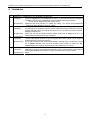
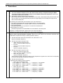
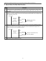
Customer Notification ZUD-F35-08-0004-01 Apr 10, 2008 Masaharu Ishikawa Hirohiko Ono, Group Manager Microcomputer Software Division Micorocomputer Operations Unit NEC Electronics Corporation CP(K),O V850E Server Operating Precautions (For On-Chip Debug Emulator) Be sure to read this document before using the product. V850E Server Operating Precautions (For On-Chip Debug Emulator) (ZUD-F35-08-0004-01) Contents 1. Introduction ......................................................................................................... 3 2. How to get EXEC and USB Driver for MINICUBE .............................................. 3 3. Information.......................................................................................................... 3 4. Limitations........................................................................................................... 4 5. Precautions......................................................................................................... 5 6. Special Notes On V850E2/ME3........................................................................ 10 7. Special Notes On Flash Memory Self-Programming Emuration ...................... 11 8. Special Notes On Data Flash Function ............................................................ 12 2 V850E Server Operating Precautions (For On-Chip Debug Emulator) (ZUD-F35-08-0004-01) 1. Introduction Please refer to the hardware document precautions file before using the emulator. 2. How to get EXEC and USB Driver for MINICUBE For Exec and USB Driver for MINICUBE information, please refer to the following URL. Exec is essential firmware for On-Chip Debug Emulator (N-Wire CARD, MINICUBE). You may get the latest version from these URL. Japanese Web site English Web site :http://www.necel.com/micro/ghs/jpn/exec/execindex.html :http://www.necel.com/micro/ghs/eng/exec/index.html 3. Information Please use the newest software version. When getting 850eserv2 newly, please contact the following company. Asia area(China/Korea): Advanced Data Controls corp. Other countries : Green Hils Software.inc 3 V850E Server Operating Precautions (For On-Chip Debug Emulator) (ZUD-F35-08-0004-01) 4. Limitations No 1 2 3 4 Description V850ES/KJ1, V850ES/KJ1+(For IE-V850E1-CD-NW only) [Limitation] Using the V850ES/KJ1 and V850ES/KJ1+ device, if you connect with DCK frequency of 20MHz, cannot connect 850eserv2 and it displays the following message. “ 0xc70 : device depend err(DCU access error)” [Workaround] Please set the DCK frequency to 10MHz. By setting “-2m” option during 850eserv2 connection, DCK frequency is set as 10MHz. PCMCIA interface card(For IE-V850E1-CD-NW only) [Limitation] IE-70000-CD-IF-A (PCMCIA interface card for NEC Electronics emulators) and the IEV850E1-CD-NW cannot be used at the same time on the same personal computer. Debugger outputs error. [Workaround] When you use the IE-V850E1-CD-NW, please check that IE-70000-CD-IF-A is not inserted to the PCMCIA slot of your computer. Host machine [Limitation] The On-Chip Debug Emulator may not respond when after returning from suspend mode depending on the host machine. [Workaround] Do not use suspend mode. When the IE-V850E1-CD-NW does not respond, remove the IE-V850E1-CD-NW from the host machine and re-insert it. When the QBV850MINI does not respond, disconnect the USB cable and re-connect it. Combination with Microsoft Windows [Limitation] [Workaround] Please do not use Microsoft Windows’s Standby feature, Pause feature, and Suspend feature after 850eserv2 invocation. Please do not use “User change” feature. None 4 V850E Server Operating Precautions (For On-Chip Debug Emulator) (ZUD-F35-08-0004-01) 5. Precautions No 1 Description Precaution for internal software break point of the MULTI (1) Since the software breakpoint set in the internal flash memory is implemented by the ROM correction function, the maximum number of the software break varies by device. Please refer to the device manual for the number. (2) Internally the software break point of the MULTI MULTI internally uses some software break points. As a result, it decreases break points that the user can set. When you set software break point, MULTI might display error message and might not be able to set the break point. The following is internal break point the MULTI use, and workaround. Top of main function(Only the V3.5 of the MULTI sets it. The V4.0 doesn't.) [Workaround] Please use "-noentbp" option, when you invoke the MULTI. Top of .syscall section. [Workaround] Please use "syscalls off" command to the 850eserv2. Step-execution in C source. [Workaround] Please set "FASTSTEP=0" from the MULTI command pane 2 Regarding -noentbp,FASTSTEP, please refer to the manual of MULTI. Regarding sysycalls command, please refer to the manual of 850eserv2. To use 850eserv2 for internal flash memory device debugging (invoke 850eserv2 with –cdnw option), please specify DCLOCK command. Please set correct value to the command, otherwize flash update does not perform correctly or destroy the flash memory. (1) Use the device file other than DF703166 V1.00, DF703134 V1.00 Input the oscillation frequency. (2) Use the device file DF703166 V1.00 When using clock through mode Input 1/3 of the oscillation frequency x2 mode Input 2/3 of the oscillation frequency. x3 mode Input the oscillation frequency. (3) Use the device file DF703134 V1.00 When using clock through mode Input 1/10 of the oscillation frequency. When using PLL mode Input the oscillation frequency. These settings forcibly change the values of the peripheral I/O register PCC and PLLCTL temporarily so that the clock speed becomes the maximum. (4) Use the device D703318Y Please use the following proper frequency. When use clock through mode 4.0V≦VDD≦5.5V,REGC=VDD ---------> Frequency = 2.0-10.0MHz 4.0V≦VDD≦5.5V,REGC= Capacitor --> Frequency = 2.0MHz 2.7V≦VDD<4.0V,REGC=VDD ---------> Frequency = 2.0MHz When using PLL mode 4.5V≦VDD≦5.5V,REGC=VDD ---------> Frequency = 2.0-5.0MHz 4.0V≦VDD<4.5V,REGC=VDD ---------> Frequency = 2.0-4.0MHz 4.0V≦VDD≦5.5V,REGC=Capacitor --> Frequency = 2.0MHz 2.7V≦VDD<4.0V,REGC=VDD ---------> Frequency = 2.0MHz 5 V850E Server Operating Precautions (For On-Chip Debug Emulator) (ZUD-F35-08-0004-01) Refer to the 850eserv2 Users Manual for details. [Example] CPU clock frequency is 5MHz, sub clock is 32768Hz dclock 5000 32768 swoff 1 2 3 1 Set the main clock value (Input decimal value/ KHz). 2 Set the sub clock value (Input decimal value/ Hz) 3 The switch of whether to use a sub clock swoff : Specifies the use of the sub clock. swon : Specifies the unuse of the sub clock. 3 Precaution for timer measurement function When MULTI are measuring of timer, in the case of being set the break point by MULTI internally, the correct data cannot get. The reason is because data is cleared as MULTI stops by internally break point. In the case that the correct data cannot get, please restrain the software break point by MULTI internally by the following way. The workaround and the point that MULTI internally set the software break point. Start of main(MULTIV3.5 is relevant and MULTIV4.0 is not relevant.) [Workaround] When MULTI connected, please set “-noentbp“ option. Start of .syscall section [Workaround] Before downloading, please set “off” at ‘syscalls’ command by 850eserv2. Step execution on C source [Workaround] Please set”FASTSTEP=0“ on MULTI command pane. Regarding noentbp,FASTSTEP, please refer to the manual of MULTI. Regarding sysycalls command, please refer to the manual of 850eserv2. 4 The address 0x7A is a system reserved area for V850ES/SG2,V850ES/SJ2 devices. Please set the 0x7A as the value (0) which is written in device users manual. 5 If bit 7 of address 0x79 in the ID code is set to 0, the use of the OCD emulator is disabled, due to the specification of the security unit mounted on the chip. As a result, the 850eserv2 cannot be activated. Please use the bit of address 0x79 to 1 always. Note of using V850E2/ME3 (1) When you set the before break point (‘e’ option by “brs” command), the device can not the parallel execution. Please note that this behavior is different from a using device. (2) When you set the after break point(‘f’ option by “brs” command), the break point is slipped (the specified address is passed before execution stops). The ROM correction function cannot be emulated. To use the CACHE command, please specify right value to the command. Otherwise, cache memory access by the debugger does not work correctly. When a hardware or software breakpoint has been set for the HALT instruction or an instruction that makes the debugger enter STOP mode, if the program is executed from that instruction, the relevant mode will be entered briefly but immediately released, and execution will resume from the next instruction. (1) The ECR register cannot modified by register window. (2) The DBPC, the DBPSW and the register for debug function(DIR,BPCn,BPAVn,BPAMn,BPDVn, BPDMn n=0,1,2,3) cannot be modified. If you set software break point at internal RAM or instruction RAM, please do not rewrite the code to which the break point is set with the user program. If you set the break point to this point, the break function does not work. In case of the system that rewrites the code by the user program, please set the software break point, after you write by the user program. If you use I/O registers that need a operation to PRCMD as preparation, the I/O registers are not written correctly when you do the following operation. (1) Step a instruction which write PRCMD. (2) Stop at a instruction which write I/O registers, then execute from it. If connect, error message will be output when the 850eserv2 is activated while the FLMD0 signal is high. Set the FLMD0 signal to low level before activating the 850eserv2. In case of IE-V850E1-CDNW, handle the FLMD0 pin in accordance with the User’s Manual 3.2.7 <1>. (At this time, the 850eserv2 automatically manipulates the FLMD0 pin level.) In case of QB-V850MINI, handle the FLMD0 pin in accordance with the User’s Manual 3.4.3 (7) (a). (At this time, the 850eserv2 automatically manipulates the FLMD0 pin level.) The access event break is delayed because of the specifications of DCU (the specified address is passed before execution stops). 6 7 8 9 10 11 12 13 14 6 V850E Server Operating Precautions (For On-Chip Debug Emulator) (ZUD-F35-08-0004-01) 15 16 The internal RAM with the BootSwap device If you reset CPU (‘a’ option is specified or no option is specified at “reset” command) with BootSwap device, the contents of the internal RAM memory are broken. Example : V850ES/SG2(μPD70F3259Y) The head 150Mbytes of the internal RAM contents are broken. When two instructions are executed simultaneously Example 1. When a breakpoint is not set Address A: MOV r1, r2 Address A+2: XOR r1, r2 Two instructions are stepped from Address A, where one instruction should be stepped. Example 2. When a breakpoint is set at address A+2 Address A: MOV r1, r2 [B] Address A+2: XOR r1, r2 A break does not occur at address A+2 if instructions are “executed continuously” from address A. 17 18 19 20 21 Example 3. When a hardware break is set at address A+2 before execution of instructions Address A: MOV r1, r2 [B] Address A+2: XOR r1, r2 The instruction at Address A is executed and break occurs if instructions are “executed in steps” from address A The PC indicates the address after halt if a break occurs in the HALT status. Before performing real-time execution, step execution is first performed on an instruction located at the PC. This causes an error in the time measurement result in the timer. In addition, when the program operation is checked using the oscillator or analog logic, the measured timing may differ between when Go is executed at a certain location and Go is executed one instruction before that location. Since the software breakpoint set in the internal flash memory is implemented by the ROM correction function, it is made invalid temporarily by a target reset or internal reset generated by the watchdog timer. The software break is made valid after a hardware break or forced break occurs. If a breakpoint is set in the vicinity of address 0 , error message will be displayed as a result of target reset or internal reset generated by the watchdog timer. Do not set breakpoints in the vicinity of address 0. (1) Restriction on execution events (when using RCU0, RCU1, or RCU2) If the address of an execution event is set in the vicinity of another execution event, the second event cannot be detected normally. This condition does not apply when the event at the second address is executed again using a branch, etc. The second event cannot be detected under the following conditions. The interval between the first and second instruction is within 4 bytes (internal ROM, internal RAM) The first and second instruction are executed consecutively (target) [Execution example] <Program example (internal ROM)> 00FE nop st 0100 nop ← 1 instruction 0102 nop Within 4 bytes 0104 nop nd 0106 nop ← 2 instruction 0108 nop <Event example> Event Name :Evt0001 Event Status :Execution Address :0x100 <Program example (target)> 00FFFFFE nop st 01000000 nop ← 1 instruction nd 01000002 nop ← 2 instruction <Event example> Event Name :Evt0001 Event Status :Execution Address :0x100 Event Name :Evt0002 Event Status :Execution Address :0x106 <Event link example> Link Name :Lnk0001 Phase1 :Evt0001 Phase2 :Evt0002 Event Name :Evt0002 Event Status :Execution Address :0x102 <Event link example> Link Name :Lnk0001 Phase1 :Evt0001 Phase2 :Evt0002 (2) Restriction on access events (when using RCU0, RCU1, or RCU2) If the address of an access event is set in the vicinity of another access event, the second event cannot be detected normally. This condition does not apply when the event at the second address is 7 V850E Server Operating Precautions (For On-Chip Debug Emulator) (ZUD-F35-08-0004-01) executed again using a branch, The second event cannot be detected under the following conditions. The interval between the first and second instruction is within 4 bytes (accessing the internal ROM or internal RAM) The interval between the first and second instruction is within 28 bytes (target) <Program example (internal ROM)> 0100 mov 0x1000, gp st 0106 ld.b 0x10[gp], r6 ← 1 instruction 010a nop Within 2 bytes nd 010c ld.b 0x12[gp], r7 ← 2 instruction 0110 nop <Event example> Event Name :Evt0001 Event Status :R/W Access Size :Byte Address :0x1010 Event Name :Evt0002 Event Status :R/W Access Size :Byte Address :0x1012 <Event link example> Link Name :Lnk0001 Phase1 :Evt0001 Phase2 :Evt0002 <Program example (target)> 0100 mov 0x100000, gp st 0106 ld.b 0x10[gp], r6 ←1 instruction 010a nop : : Within 28 bytes : 0110 nop nd 0120 ld.b 0x12[gp], r7 ← 2 instruction 22 <Event example> Event Name :Evt0001 Event Status :R/W Address :0x1010 Event Name :Evt0002 Event Status :R/W Address :0x1012 <Event link example> Link Name :Lnk0001 Phase1 :Evt0001 Phase2 :Evt0002 Restriction on event detection during misalign access (1) Restriction on write access event No events can be detected. (2) Restriction on read access event Events can be detected by setting the read access event as shown below. Operation of Execution Instruction Size address (Multiple of 4)+0 (Multiple of 4)+1 Word (Multiple of 4)+2 (Multiple of 4)+3 (Multiple of 4)+0 Half (Multiple of 4)+1 Word (Multiple of 4)+2 (Multiple of 4)+3 Event Condition address (Multiple of 4)+0 (Multiple of 4)+1 (Multiple of 4)+2 (Multiple of 4)+3 (Multiple of 4)+0 (Multiple of 4)+1 (Multiple of 4)+2 (Multiple of 4)+3 Access Size Word Byte Half Word Byte Half Word Byte Half Word Byte Detection Status Data 0x44332211 0x22 0x4433 0x44 0x2211 0x22 0x4433 0x44 [Memory status] 3FF8000 +0 11 +1 22 +2 33 +3 44 [Execution example (a)] 0xFFE 01000 01006 01008 <Event example> Event Name :Evt0001 Event Status :R Access Size :Byte Address :0x3FF8001 Data :0x22 nop mov 0x3FF8001, gp nop ld.w 0x0[gp], r6 [Execution example (b)] 0xFFE 01000 01006 01008 <Event example> Event Name :Evt0001 Event Status :R Access Size :Half Word Address :0x3FF8002 Data :0x4433 nop mov 0x3FF8002, gp nop ld.w 0x0[gp], r6 8 Detected Detected Detected Detected Detected Detected Detected Detected (a) (b) (c) V850E Server Operating Precautions (For On-Chip Debug Emulator) (ZUD-F35-08-0004-01) [Execution example (c)] 0xFFE 01000 01006 01008 23 24 25 26 27 28 29 <Event example> Event Name :Evt0001 Event Status :R Access Size :Byte Address :0x3FF8001 Data :0x22 nop mov 0x3FF8001, gp nop ld.w 0x0[gp], r6 The WAIT mask option by PINMASK command can be used only in products that include RCU1 or RCU2 (under development). Whether an internal reset generated by the watchdog timer can be masked by the RESET mask option by PINMASK command or not varies depending on the device used. Restrictions on event detection using bit manipulation instruction When the access size of an event is set to Byte and the event is set at an address other than a multiple of 4, if the address is accessed by a bit manipulation instruction, an incorrect event may be detected or no event may be detected. When the access size of an event is set to Bit and the event is set at an address other than a multiple of 4, if the address is accessed by a bit manipulation instruction, an incorrect event may be detected or no event may be detected. A pin reset during a break is masked and the CPU or peripheral I/O cannot be reset. In addition, the CPU or peripheral I/O may not be reset sometimes if a pin reset or internal reset occurs when data is overwritten by Memview or MEMORY command during user program execution. CPU or peripheral I/O cannot be reset as the following case. During a break (Because the reset pin is masked during a break) When you connect AZ850 made by NEC Electronics, the hardware trace method cannot be used. Use the software trace method instead. When you use Exec and 850eserv2, MULTI displays the following warning message and MULTI can not connect. EXEC library Vx.xx is too old. Please use EXEC Vx.xx or later. Please use the newest Exec version. 9 V850E Server Operating Precautions (For On-Chip Debug Emulator) (ZUD-F35-08-0004-01) 6. Special Notes On V850E2/ME3 No 1 2 3 Description Limitation for V850E2/ME3 If you access the register related to USB when a clock is not input to UCLK(USB External Clock Input), MULTI will hang-up. [Workaround] Please do not refer to all sfr register by “sfr” command. Please do not access USB related register by “sfr” command. If you write the following setting of SFR on the connection file( ex) rc file), when you access these registers, MULTI does not hang-up. (1) Case of don’t use USB (i) UCKC.UCDIV1=1 ;USB clock(fusb) set internal clock (ii) Execute other initialization procedure. (2) Case of use USB (i) PM1.PM10=1 ;P10 set the input mode(*1) (ii) PFC1.PMC10=1 ;P10 set the both use mode (iii) PFC1.PFC10=1 ;UCLK set input mode (iv) UCKC.UCDIV1=0 ;USB clock(fusb) set external clock(*2) (v) Execute other initialization method. *1) You don't need to set PM1 register after a reset, because the default value of it is FFH. *2) You don’t need to set UCKC register after a reset, because the default value of it is 00H. Precaution for the break before the execution If you set the break before the execution( When you set ‘e’ option of “brs” command ), the instruction is not executed in parallel. This behavior is different from the device. Precaution for the break after the execution The break after the execution ( When you set ‘f’ option of “brs” command ) is delayed (the specified add ress is passed before execution stops). 10 V850E Server Operating Precautions (For On-Chip Debug Emulator) (ZUD-F35-08-0004-01) 7. Special Notes On Flash Memory Self-Programming Emuration No 1 Description No break occurs in an interrupt service routine acknowledged during self-programming, even if an event breakpoint has been set. (V850E1, D70F3259) 2 Do not set a software break in the internal flash memory area. (V850E1, V850ES) 3 A forcible break can be accepted even if flash memory self-programming is in progress. However, user cannot debug correctly then. After the forcible break, re-execute immediately or reset the CPU. (V850E1, D70F3259) Cannot use disassemble feature or Memview due to the internal flash memory value has not updated correctly in the middle of the execution of the self-programming function. (V850E1, V850ES) Do not use the peripheral break function, if you use the flash self programming function in your program. Please set “pb” command OFF. If you set “pb” command ON, the contents of the internal flash memory may destroyed. 4 5 11 V850E Server Operating Precautions (For On-Chip Debug Emulator) (ZUD-F35-08-0004-01) 8. Special Notes On Data Flash Function No Description When you access to the data flash merory area by way of the library, unexpected break may occur. To a 1 void this phenomenon, please disable the guard break function for internal RAM (set “ramgrd” option of “flsf” command) and disable the gurad break function for SFR(set “sfrgrd”,”sfrwp”,”sfrrp” option of “flsf” command) When you set the user memory from 0xX00000 to 0xXf7fff, the data flash memory area which is from 2 0xX80000 to 0xXfffff is considered as the user memory too. It is because the Exec allocates the user memory by the unit of 1MBytes. In this case, the fail-safe-break doesn't happen even if a program writes to the data flash memory area. Case of CS0 0x1fffff data flash memory 0x1f8000 Mapping to user memory Can set 1MBytes target memory 0x100000 3 When you set the data flash memory area by “dfmap” command, the area from 0xX00000 to 0xX7ffff becomes accessable even if you don't set anything to the area. It is because the Exec handles the data flash memory area by the unit of 1MBytes. In this case, the fail-safe break doesn't happen even if a program reads the area from 0xX00000 to 0xX7ffff. Case of CS0 0x1fffff data flash memory 0x1f8000 Mapping of target ROM memory Can set by 1MBytes 0x100000 4 Cannot set the software break point at data flash memory area. If you set the break point at data flash area, please use the hardware break point. 12