1
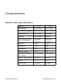
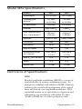
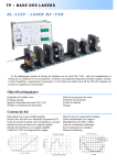
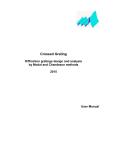
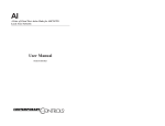
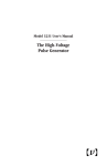
USER’S GUIDE High-Frequency Electro-Optic Phase Modulators Models 442x, 443x, & 485x U.S. Patent # 5,414,552 3635 Peterson Way • Santa Clara, CA 95054 • USA phone: (408) 980-5903 • fax: (408) 987-3178 e-mail: [email protected] • www.newfocus.com MASTER Warranty Newport Coporation guarantees its products to be free of defects for one year from the date of shipment. This is in lieu of all other guarantees, expressed or implied, and does not cover incidental or consequential loss. Information in this document is subject to change without notice. Copyright 2012, 2001-1998, Newport Corporation. All rights reserved. The New Focus logo and symbol are registered trademarks of Newport Corporation Document Number 440018 Rev. E Contents Operation 5 Introduction . . . . . . . . . . . . . . . . . . . . . . . . . . . . . . . . . . . . .5 Quick Start . . . . . . . . . . . . . . . . . . . . . . . . . . . . . . . . . . . . . .8 Using the Modulator. . . . . . . . . . . . . . . . . . . . . . . . . . . . . . .9 Principles of Operation 15 The Electro-Optic Effect . . . . . . . . . . . . . . . . . . . . . . . . . .15 Creating Sidebands. . . . . . . . . . . . . . . . . . . . . . . . . . . . . . .16 Cavity Design . . . . . . . . . . . . . . . . . . . . . . . . . . . . . . . . . . .18 Characteristics 19 Model 442x Specifications. . . . . . . . . . . . . . . . . . . . . . . . .19 Model 443x Specifications. . . . . . . . . . . . . . . . . . . . . . . . .20 Model 485x Specifications. . . . . . . . . . . . . . . . . . . . . . . . .21 Definitions of Specifications . . . . . . . . . . . . . . . . . . . . . . .21 Customer Service 25 Technical Support. . . . . . . . . . . . . . . . . . . . . . . . . . . . . . . .25 Service . . . . . . . . . . . . . . . . . . . . . . . . . . . . . . . . . . . . . . . .25 Performance Data Phase Modulators 27 Contents • 3 4 • Contents Operation Introduction The New Focus Models 44xx and 485x high-frequency electro-optic phase modulators provide an efficient means of single-frequency optical phase modulation in the 0.25 to 13-GHz frequency range. These modulators are useful components in a variety of experimental techniques, including FM spectroscopy, laser-frequency stabilization, atom cooling, laser-linewidth broadening, and laser-guide star systems. These modulators feature low drive voltages, large modulation depths, a wide range of operating frequencies (from 0.25 to 13 GHz), a broad range of wavelengths (from 0.5 to 1.6 µm), low optical insertion loss, and high optical power handling capability. Their 1- to 2-mm apertures make them compatible with most laser sources. Finally, the electro-optic materials used in these devices are nonhygroscopic, so they can be left on an optical table for indefinite periods without requiring a sealed enclosure. These high-frequency phase modulators are classified into three resonant frequency ranges: Model Phase Modulators Frequency Range 4421, 4423 0.25 to 2.0 GHz (see Figure 1) 4431, 4433 2.0 to 4.6 GHz (see Figure 2) 4851, 4853 6.8 or 9.2 GHz (see Figure 3) Operation • 5 The modulator is shipped to you with the resonant frequency set to the frequency specified when your order was placed with New Focus. The operating wavelengths are determined by the broadband anti-reflection coating applied to the surfaces of the electro-optic crystals. Two standard wavelength ranges are offered: 0.5–0.9 µm and 1.0–1.6 µm. For applications requiring even better anti-reflection coatings, contact New Focus to obtain a customized, narrow-band “V” coating. The physical characteristics and performance specifications for these modulators are listed beginning on page 19. Mechanical drawings of the three types of modulators are shown in Figures 1 to 3. Figure 1: Mechanical views of the Model 442x SMA Input Connector 442X Vis/IR Phase Modulator Frequency Adjust 2.08 (52.8) .45 (11.4) 2.19 (55.6) .64 (16.3) D* .08 (2.0) X .08 (2.0) Optical Aperture, Both Sides * Height "D" is frequency dependent .91 (23.1) 6 • Operation 1/4-20 (M6) Mounting Hole 1.82 (46.2) Delrin Base Figure 2: Mechanical views of the Model 443x SMA Input Connector 442X Vis/IR Phase Modulator Frequency Adjust .32 (8.2) 1.14 (29.0) 1.41 (35.8) D* .04 (1.0) X .04 (1.0) Optical Aperture, Both Sides Delrin Base * Height "D" is frequency dependent 1.03 (26.2) 1/4 - 20 (M6) Mounting Hole .52 (14.2) Figure 3: Mechanical views of the Model 485x .40 (10.1) 485X Vis/IR Phase Modulator Made in USA SMA Input Connector 2.28 (57.9) Frequency Adjust 1.55 (39.4) 1.00 (25.4) .08 (2.0) X .04 (1.0) Optical Aperture, Both Sides .90 (22.9) Delrin Base 1.04 (26.4) .53 (13.5) .79 (20.1) .79 (20.1) 2X 8-32 (M4) Mounting Hole 1/4-20 (M6) Mounting Hole .35 (8.9) Phase Modulators Operation • 7 Quick Start This section presents a brief introduction to using your high-frequency phase modulator. 1. Align a collimated optical beam through the mechanical apertures of the modulator. For Models 44xx the beam should be polarized vertically (with respect to the modulator casing), and for the Models 485x the beam should be polarized horizontally. Be careful not to exceed the maximum recommended optical power, or damage to the electro-optic crystal could result. (See page 11 for a discussion of optical damage.) 2. Drive the modulator with a 50- RF driver tuned to the modulator’s resonant frequency. RF powers from 0.1 to 0.5 watts should be sufficient to allow observation of sidebands. Generally, an optical spectrum analyzer with suitable finesse and free spectral range is used to observe the modulation sidebands. To prevent damaging the electro-optic crystal, do not exceed the modulator’s maximum RF drive power (4 watts for Models 44xx; 3 watts for Models 485x). 3. Use the tuning slug to fine tune the modulator’s resonant frequency and precisely match it to the RF drive frequency. If the modulator is not driven at or close to its resonant frequency, most of the RF drive power will be reflected, which could damage to the driver. 8 • Operation Using the Modulator When used properly, the New Focus electro-optic phase modulators can provide efficient optical phase modulation with extremely low unwanted amplitude modulation and insertion loss. The key to obtaining this pure phase modulation is good alignment of the optical beam with the crystal’s propagation axis and accurate orientation of the polarization of the beam along the crystal’s electro-optic axis. If the beam is not properly aligned, a phase modulator will impose a polarization rotation (as well as a phase modulation) which can lead to unwanted amplitude modulation if the modulator is followed by any polarizing optics. It is important to carefully align the polarization since the crystals used by New Focus are cut so that the beam propagates along the y-axis of the crystal. This orientation minimizes the effects of acoustic resonances but makes it critical that the optical beam be linearly polarized along the crystal’s z-axis. Aligning an Optical Beam Through the Modulator To align the module to the optical beam: 1. Use the 1/4-20 (M6 for metric versions) tapped hole located on the base of the module to mount it on an adjustment-positioning device for alignment. We recommend the New Focus Model 9071 or 9071M tilt aligner because of its tilt and translation capabilities. 2. Turn on the optical beam, and orient the beam so it is linearly polarized along the z-axis of the electro-optic crystal. With the Model 44xx modulators the polarization should be oriented vertically with respect to the modulator casing, and with the 485x modulators the polarization should be horizontal. Phase Modulators Operation • 9 3. Position and align the module so that the beam passes through the mechanical apertures, clearing them without clipping. The beam should be collimated with a waste size less than the aperture size and such that the Rayleigh range is at least the length of the crystal. A good rule of thumb is that the beam diameter should be about one-third the aperture size to minimize clipping. For a 2-mm aperture a good beam size is 0.5–1 mm, and for a 1-mm aperture a good beam size is 250–500 µm. Larger beams can be focused slightly and then collimated after the modulator using a pair of lenses. If you do this, keep in mind the intensity of the beam inside the modulator crystal, and make sure the intensity does not exceed the damage threshold (see the discussion of optical damage on page 11). Driving the Modulator Connect the SMA jack on the modulator to an RF driver using an RF cable with operating bandwidth greater than the modulation frequency to minimize propagation losses. Note The optical alignment of the modulator can be disturbed by the RF cable, so it is a good idea to use a strain relief on the cable. The Models 44xx and 485x high-frequency phase modulators are resonant devices with a 50 impedance when driven at their resonant frequency. These modulators require an RF driver matched to 50 and tuned to the resonant frequency of the modulator. New Focus does not sell RF synthesizers, oscillators or amplifiers, but suitable sources are available from other companies. New Focus engineers can provide help in finding the source that’s right for your modulator and your application. Feel free to contact us for assistance. 10 • Operation The RF driver typically consists of an oscillator or synthesizer followed by an RF amplifier. The RF driver should be capable of generating output powers in the 1 to 4 watt range. For many applications 1 watt is sufficient to generate a suitable phase shift. Note that if the modulator is driven with RF powers greater than about 3 watts, the modulator casing can heat up noticeably. This heating can cause some shifting of the modulator’s resonant frequency, and it can lead to thermal lensing in the crystal. Finally, note that if the modulator is not driven at (or close to) its resonant frequency, most of the RF drive power will be reflected back to the driver. Excessive RF power reflected back from the modulator to the RF driver will not harm the modulator but can damage the driver. So, when driving the modulator, be sure that the RF source is matched to the modulator’s resonant frequency. Ensuring that the drive frequency is matched to the modulator can be done either by observing the optical sidebands on an optical spectrum analyzer or by measuring and minimizing the amount of RF power that is reflected from the modulator. Use the tuning slug to fine tune the modulator’s resonant frequency to precisely match the RF drive frequency. Alternately, tune the RF drive frequency until it matches the modulator’s resonant frequency. Preventing Photorefractive Damage The electro-optic crystals used in these modulators are susceptible to optical damage through the photorefractive effect. This phenomenon is caused by the migration of photoexcited charge carriers from illuminated regions to darker regions. The localized refractiveindex variations resulting from the space-charge field and the electro-optic effect reduce the effectiveness of the modulators and cause distortion to the optical beam traveling through the modulator. Phase Modulators Operation • 11 Photorefractive damage is a serious concern for visible wavelengths, high optical power, and tightly focused beams. The photorefractive damage process can occur gradually over days or hours, or, for high optical powers and short wavelengths, this effect can occur over seconds. A damaged crystal will distort a beam, usually by elongating it along one axis. If operating close to the damage threshold, it is a good idea to monitor the transmitted beam periodically for indications of optical damage. If you input more optical intensity than recommended, photorefractive damage will occur. In reality, this “damage” is not permanent. Photorefractive damage can be (at least partially) reversed by carefully annealing the crystal and thus mobilizing the charge carriers. Due to the sensitive parts contained inside the modulator housing, however, this process should only be done at New Focus. Please contact us for more details. Our modulators use two types of electro-optic materials, LiNbO3 and magnesium-oxide (MgO) doped LiNbO3. The LiNbO3 material has a lower damage threshold, and so it is used in our IR modulators which operate from 1.0 to 1.6 µm. In this wavelength range photorefractive damage is generally not a serious problem; we recommend a maximum optical intensity of 1 W/mm2 at 1.3 µm. The visible modulators, which operate from 500-900 nm, come standard with MgO-doped LiNbO3 crystals. The MgO doping increases the resistance to photorefractive damage, enabling this material to be used in the visible wavelength range. For MgO-doped LiNbO3, the recommended maximum optical intensity is 5 W/mm2 at 647 nm for a 1-mm diameter beam. Keep in mind that the optical damage threshold depends on many factors, including wavelength, beam diameter, and the particular batch of crystal material being used. The damage thresholds are conservatively 12 • Operation stated to avoid this problem. However, it is difficult to guarantee damage-free performance at a specific wavelength and power. Typically, the damage issue is most problematic for wavelengths shorter than 600 nm, where the photorefractive damage process becomes more efficient and the maximum optical power drops off sharply as the wavelength gets shorter. Also, note that the damage specifications given here assume a 1-mm diameter beam. The damage process is more of a problem for tightly focused beams, and so, for smaller diameter beams the damage threshold intensities are lower than the values given here. If you have a concern about photorefractive damage in your particular application, please contact New Focus. Phase Modulators Operation • 13 14 • Operation Principles of Operation The Electro-Optic Effect Operation of the New Focus electro-optic phase modulators is based on the linear electro-optic (or Pockels) effect, whereby an applied electric field induces a change in the refractive index of the crystal. With electro-optic devices, phase modulation is achieved by aligning the polarization of the optical beam along the z-axis of the electro-optic crystal. By applying an electronic drive signal to the crystal, the phase of the optical beam is then modulated through the electro-optic effect. The material used in these modulators are lithium niobate (LiNbO3) and magnesium-oxide-doped lithium niobate (MgO:LiNbO3). These materials are well-suited for use in these types of modulators because they have wide optical transparency windows, large electro-optic coefficients, and low RF losses. Having low RF loss is the key to making efficient, high-Q devices that operate at frequencies up to 13 GHz. The large electro-optic coefficient of lithium niobate means that these modulators require low drive voltages and have large modulation depths. In addition, by putting the crystal in a resonant microwave cavity, the resonant enhancement of the voltage across the crystal further reduces the required input drive voltage while still allowing a relatively large optical aperture. Phase Modulators Principles of Operation • 15 Creating Sidebands Phase modulators are typically used to generate frequency sidebands on a cw optical beam. A sinusoidal electronic drive signal applied to the modulator produces optical sidebands which are separated from the cw optical carrier by the drive frequency. These modulation sidebands can be observed using an optical spectrum analyzer. Given an induced peak optical phase shift of (in radians), the fraction of power transferred to each of the first-order sidebands is [J1( )]2, where J1 is the Bessel function of order one. The fraction of power that remains in the carrier is [J0( )]2, where J0 is the Bessel function of order zero. For example, imposing a phase modulation with peak phase shift of 1 radian will transfer 19% of the optical carrier power to each of the first-order sidebands and leave 59% of the power in the carrier. The maximum power that can be transferred to each of the first-order sidebands is about 34%, and this requires a peak phase shift of 1.8 radians. For the Model 442x operating with 532 nm light, a 1.8 radian phase shift requires a peak drive voltage of about 13 volts (1.7 W average power). The effect of an applied electric field on a crystal’s refractive index is described by a third-rank tensor rij. The induced refractive index change caused by an external electric field has the form n=1/2ne3r33E where n is the change in the index of refraction, ne is the unperturbed index of refraction, r33 is the appropriate element in the electro-optic tensor, and E is the applied electric field. The New Focus phase modulators consist of an electro-optic crystal of length l, width b, and thickness d. The electric field is applied along the crystal’s z-axis 16 • Principles of Operation and transverse to the direction of optical propagation. Modulation is induced onto the laser beam by aligning the polarization of the input beam with the z-axis of the crystal. An electronic signal is then directly modulated onto the laser beam through the electrooptic effect. The optical phase shift obtained by applying a voltage V across the electro-optic crystal is 2 1 3 l = ------ --- n e r 33 --- V 2 d where is the free-space wavelength. A commonly used figure of merit for electro-optic modulators is the half-wave voltage, V, which is the voltage required to produce a ¼ phase shift. Substituting into the preceding equation yields d V = -------------3 n e r 33 l For these high-frequency phase modulators, the crystal is put into a resonant microwave cavity that enhances the voltage applied across the crystal. This results in a voltage across the crystal that can be more than nine times the applied input drive voltage, leading to reduced half-wave voltages and larger modulation depths. For these modulators, the peak phase shift obtained by applying a sinusoidal signal of average power P at the input SMA connector is 2 1 3 2PQl = ------ --- n e r 33 ------------- bd 2 where Q is the quality factor of the resonant cavity, is the drive frequency, and is the crystal permittivity. For the Model 442x high-frequency phase modulators V is typically 45 volts at 1.06 µm, corresponding to a modulation depth of 0.07 radians/volt. Note that these values scale with wavelength, so at 532 nm V is 23 volts, and the modulation depth is 0.14 radians/volt. Phase Modulators Principles of Operation • 17 Cavity Design Models 442X and 443X (0.25–4.6 GHz) For the Models 44xx modulators the crystal is placed in a resonant microwave cavity to achieve a high Q (>100) system (see “Quality Factor (Q)” on page 24). The microwave cavity is designed to replicate a transmission line terminated by the crystal. Given the crystal’s capacitance, the transmission line length is chosen so that the line resonates at the desired frequency. Typically, the resonance has bandwidth of 0.5–1% of the resonant frequency, allowing the device to be operated over this narrow frequency range. In addition, these modulators are equipped with a tuning slug that probes the interior of the microwave cavity and provides frequency tuning over a range of up to 200 MHz. Model 485X (6.8 or 9.2 GHz) For frequencies above 3 GHz, the crystal length required to maintain phase matching becomes too short to obtain reasonable modulation depth, and a different design is required. The Model 485x employs a patented design to match the microwave velocity through the resonant cavity with the optical velocity through the crystal. This is accomplished with a microwave waveguide where the velocity of the microwave radiation is geometry dependent. By adjusting the geometry so the optical and microwave velocities are equal, the crystal length can be made long enough to achieve significant modulation depth. The cavity is equipped with a tuning slug that allows manual adjustment of the resonant frequency over a range of up to 100 MHz. The Model 485x has a 1x 2-mm aperture, and the optical beam must be horizontally polarized with respect to the modulator housing. 18 • Principles of Operation Characteristics Model 442x Specifications Model # Phase Modulators 4421 4423 Wavelength 0.4–0.9 μm 1.0–1.6 μm Operating Frequency 0.25–2.0 GHz 0.25–2.0 GHz RF Bandwidth 0.5% freq. 0.5% freq. Material MgO:LiNbO3 LiNbO3 Max. Optical Power (in a 1-mm beam) 2 W/mm2 (532 nm) 4 W/mm2 (1.06 μm) Aperture 2 mm 2 mm Connector SMA SMA Impedance 50 Ω 50 Ω Max. RF Power 4W 4W Modulation Depth (at 1.06 μm) >=0.05 rad/V >=0.05 rad/V Max. V¼ (at 1.06 μm) 31-63 V 31-63 V VSWR <1.5 <1.5 Return Loss >14 dB >14 dB Characteristics • 19 Model 443x Specifications Model # 4431 4433 Wavelength 0.4–0.9 μm 1.0–1.6 μm Operating Frequency 2.0–4.6 GHz 2.0–4.6 GHz RF Bandwidth 0.5% freq. 0.5% freq. Material MgO:LiNbO3 MgO:LiNbO3 Max. Optical Power (in a 1-mm beam) 2 W/mm2 (532 nm) 4 W/mm2 (1.06 μm) Aperture 1 mm 1 mm Connector SMA SMA Impedance 50 Ω 50 Ω Max. RF Power 4W 4W Modulation Depth (at 1.06 μm) >=0.04 rad/V >=0.04 rad/V Max. V¼ (at 1.06 μm) 45-79 V 45-79 V VSWR <1.5 <1.5 Return Loss >14 dB >14 dB 20 • Characteristics Model 485x Specifications Model # 4851 4853 Wavelength 0.4–0.9 μm 1.0–1.6 μm Operating Frequency* 9.2 GHz or 6.8 GHz 9.2 GHz or 6.8 GHz RF Bandwidth 0.5% freq. 0.5% freq. MgO:LiNbO3 LiNbO3 2 W/mm2 (532 nm) 4 W/mm2 (1.06 μm) 1 mm x 2 mm 1 mm x 2 mm Connector SMA SMA Impedance 50 Ω 50 Ω Max. RF Power 3W 3W 0.05 rad/V >=0.04 0.05 rad/V >=0.04 Max. V¼ (at 1.06 μm) 79 V 79 V VSWR <1.5 <1.5 >14 dB >14 dB Material Max. Optical Power (in a 1-mm beam)** Aperture Modulation Depth (at 1.06 μm) Return Loss Definitions of Specifications RAM Residual amplitude modulation (RAM) is a source of unwanted noise in a phase-modulation system. An ideal phase modulator will exhibit no RAM. However, etalons in the crystal and misalignment of the optical beam will lead to some amplitude modulation. With careful adjustment of an optical beam’s alignment and polarization, our modulators will exhibit less than -60 dB of RAM for a 1-radian peak phase shift. Phase Modulators Characteristics • 21 Wavelength Two standard broadband AR-coatings are available: 0.5–0.9 µm and 1.0–1.6 µm. Each coating has a 1% maximum reflectivity per surface. The optical losses in the modulators are determined by the absorption and scatter of light in the electro-optic crystal and by the quality of the anti-reflection coatings on the end faces. The crystals typically have losses of 0.3%/cm at 1.0 µm. So, for a 2-cm long crystal, the total insertion loss will be about 2.6% at 1.0 µm. Operating Frequency The range of resonant frequencies over which these modulators can be designed to operate. The particular resonant frequency of a given modulator is specified at the time the modulator is ordered. RF Bandwidth The bandwidth of the modulator’s resonant frequency, otherwise known as the 3-dB frequency. It is the range over which at least one-half of the electrical drive power will be transferred to the modulator. Material The modulators use MgO-doped LiNbO3 and the IR modulators use LiNbO3. Max. Optical Intensity This is the maximum optical intensity (assuming a 1-mm diameter beam) that can be passed through the crystal before photorefractive damage occurs. Note that this optical damage threshold is strongly wavelength dependent. (See page 11 for a discussion of photorefractive damage.) 22 • Characteristics Aperture The size of the mechanical aperture at the input and output of the modulator. The aperture aids optical alignment and ensures that the beam passes through the center of the crystal. Connector All modulators have female SMA input connectors. Impedance Resonant phase modulators are matched to 50 ⍀, and this is the input impedance seen by the RF driver. Max. RF Power The maximum recommended RF drive power. Above this power, thermal effects in the crystal (such as thermal lensing) will become a problem and the modulator’s resonant frequency will drift significantly. Modulation Depth The resulting optical phase shift when a 1-volt signal is applied to the modulator. The modulation depth is specified at 1.06 µm. The modulation depth varies inversely with wavelength. So, for example, the modulation depth at 532 nm is twice that at 1.06 µm. Max. V The voltage required to achieve a 180-degree phase shift at 1.06 µm. V varies linearly with wavelength, and so, V at 532 nm is half that at 1.06 µm. Return Loss: Describes how well the modulator is matched to 50 ⍀ when driven at its resonant frequency. A high return loss indicates a good impedance match between the driving source and the modulator. With a high return loss, power transfer to the Phase Modulators Characteristics • 23 modulator is optimized, and reflected power, which can harm the driving source, is minimized. All New Focus resonant phase modulators are tested by measuring return loss versus frequency around the resonant frequency. The results of this test are provided at the end of this manual. For a power reflection coefficient R, the return loss in dB is -10 logR. A Return loss of 14 dB corresponds to 4% of the incident RF power reflected back to the driver. VSWR The voltage standing-wave ratio is another way to specify the quality of impedance matching between RF driver and resonant modulator. VSWR is defined as the voltage ratio between the maximum and minimum of the standing wave that occurs because of impedance mismatch. Given a return loss RL (in dB), the VSWR can be found from – RL 20 + 10 VSWR = 1 ---------------------------------– RL 20 1 – 10 A VSWR value of 1 indicates a perfectly matched system. A VSWR of 1.5 corresponds to 4% of the incident RF power reflected back to the driver. Quality Factor (Q) The quality factor, or Q, of a resonant cavity is a measure of the sharpness of its frequency response. Generally, a larger Q means a higher modulation depth. For highfrequency phase modulators, Q is defined as f/⌬f, where f is the modulator’s resonant frequency and ⌬f is the full width of the modulator’s resonance (measured at the 3-dB points, where the modulator absorbs onehalf of the incident RF drive power). For the high-frequency phase modulators Q is typically between 100 and 200. The measured Q for your modulator is written in the performance data section at the end of this manual. 24 • Characteristics Customer Service Technical Support Information and advice about the operation of any New Focus product is available from our applications engineers. For quickest response, ask for “Technical Support” and know the model and serial number for your product. Hours: 8:00–5:00 PST, Monday through Friday (excluding holidays). Toll Free: 1-866-NUFOCUS (1-866-683-6287) (from the USA & Canada only) Phone: (408) 980-5903 Support is also available by fax and email: Fax: (408) 987-3178 Email: [email protected] We typically respond to faxes and email within one business day. Service In the event that your New Focus product malfunctions or becomes damaged, please contact New Focus for a return authorization number and instructions on shipping the unit back for evaluation and repair. Phase Modulators Customer Service • 25 26 • Customer Service Performance Data Model Number: ______________________________ Serial Number:_______________________________ Resonant Frequency: __________________________ Wavelength: _________________________________ Input RF Power: _____________________________ Return Loss: ________________________________ VSWR: ____________________________________ Q: _________________________________________ Phase Modulators Performance Data • 27 28 • Performance Data