1
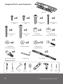
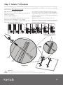
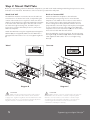
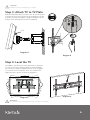
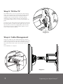
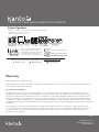
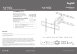
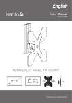
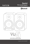
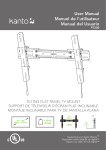
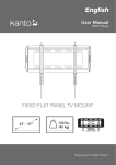
English
User Manual
FMX2 TV Mount
FULL MOTION FLAT PANEL TV MOUNT
+14°/-8°
75 x 75
to
800 x 450
37” - 80”
130 lbs
(59 kg)
VESA
3.8– 20”
±80°
(10–56 cm)
COMPLIANT
Supporting your digital lifestyle™
Table of Contents
Table of Contents / Introduction . . . . . . . . . . . . .
Supplied Parts & Hardware . . . . . . . . . . . . . . . . . .
Setup - Step 1 . . . . . . . . . . . . . . . . . . . . . . . . . . . .
Setup - Step 2 . . . . . . . . . . . . . . . . . . . . . . . . . . . .
2
3
4
5
Setup - Steps 3 to 4 . . . . . . . . . . . . . . . . . . . . . . . .
Setup - Steps 5 to 6 . . . . . . . . . . . . . . . . . . . . . . . .
Other Kanto Products . . . . . . . . . . . . . . . . . . . . . .
Warranty . . . . . . . . . . . . . . . . . . . . . . . . . . . . . . . .
6
7
8
8
Introduction
Thank you for choosing a Kanto full motion TV wall mount. The FMX2 is designed to mount flat panel televisions weighing up
to 130 lbs (59 kg), extend up to 20” (56 cm) from your wall, allows you to swivel left and right 80°, and tilt your TV +14°/-8°. You
can also adjust the horizontal level ±5°.
Read these instructions fully before installation of this mount. If you do not understand these directions, or have any
doubts about the safety of the installation, please consult a qualified installation contractor to install this mount. Make
sure there are no defective or missing parts. Do not use defective parts. If there is hardware missing, or if you are
uncertain whether the part is defective call Kanto directly at 1-888-848-2643 or email [email protected]. This
product should not be mounted on steel stud walls or cinder block walls. Consult a qualified installation contractor if
you are unsure about the type of wall you may have. Kanto cannot be liable for property damage or injury caused by
incorrect mounting, incorrect assembly, lifting or incorrect use of this product.
See installation video online at:
www.kantoliving.com/product/mounts/FMX2#video
Visit our Website for the most recent version of this manual.
CAUTION
The maximum loading weight is 130 lbs (59 kg). This wall mount is intended for use up to the maximum weight
restrictions indicated. Use with products heavier than the maximum weights indicated may result in instability causing
possible injury.
CAUTION
The wall you plan to affix the Kanto mount to must be able to support more than 5 times the weight of the
television and the wall mount combined. Do not use this product for any purpose other than to mount a flat panel
TV on a vertical surface as outlined in this manual. Improper installation may cause damage to your TV or serious
injury. This product should not be mounted to steel stud walls, cinder block or old concrete walls. Consult a qualified
installation contractor if you are unsure about the type of wall you may have.
2
Supplied Parts and Hardware
Wall Plate
x4
A: M5 x 12mm
Bolt
B: M6 x 12mm
Bolt
x4
x4
E: M6 x 35mm
Bolt
x4
C: M8 x 25mm
Bolt
D: M5 x 30mm
Bolt
x4
F: M8 x 40mm
Bolt
x4
I: M5/M6/M8
5mm Plastic Spacer
x4
x4
x4
J: M5/M6 Washer
x8
G: M5/M6
14mm Plastic Spacer
H: M5/M6/M8
10mm Plastic Spacer
x6
x10
K: M8 Washer /
Lag Bolt Washer
x6
L: Lag Bolt
x2
M: Concrete Anchor
N: Allen Key
R: TV Bracket
Required Tools
Socket
set
3
Phillips
Screwdriver
Hammer (for
concrete
installs)
Crescent
Wrench
Stud
Finder
Level
Drill
3/8”
Masonry
Bit
7/32”
Wood
Bit
Supporting your digital lifestyle™
Step 1: Attach TV Brackets
There are a wide variety of TVs available that require an assortment of bolt sizes. We provide a selection of mounting
bolts to fit most TVs. If you have any concerns about this mounting hardware or installation call us direct at 1-888-8482643 or email at [email protected].
Step 1.1 Select the correct size of bolt
Kanto provides 3 bolt diameters (Metric sizes M5, M6 and
M8) in various lengths.
Part items: A, B, C, D, E, or F.
Select the correct diameter bolt and hand screw into the
back of the TV to determine the correct length.
Use washer (J) for bolts A, B, D or E (M5 or M6 size), and
washer (K) for bolts C or F (M8 size).
If your TV has a curved back or the mounting holes are
recessed, you can use a combination of spacers (G, H or
I, depending on the selected bolt) to ensure a proper fit.
You can use spacers inside or outside the bracket arm, as
shown in Diagram A.
Step 1.2 Attach TV brackets to the back of the TV
Now that you have selected the correct bolt length and
combination of spacers, it’s time to attach the brackets to
the TV, as shown in Diagram A.
Combination of spacers (G, H or I),
depending on length of bolt and
depth of recess
OR
Bolt
(A thru F)
Washer
(J or K)
Diagram A
WARNING
Never overtighten a bolt into the back of your flat panel TV.
Do not lay the TV face down on its glass front. Use a TV stand or lean against a wall.
4
Step 2: Mount Wall Plate
Before you start drilling, attach the Wall Plate Template to your wall. It will make marking and drilling level pilot holes easier,
and catch a lot of the dust. Remember to remove it before you attach the wall plate!
Wood Stud Wall
Brick or Concrete Wall
The Wall Plate must be mounted to two wood studs. Use
a stud sensor to locate the two studs, clearly marking the
centers of the studs. Use a long level to make sure these
marks are horizontally level. Attach the Wall Plate Template
to the wall at the desired height so that the stud centers
are visible through mounting slots, and drill four pilot
holes. Once you have drilled the pilot holes, remove the
Wall Plate Template.
Attach the Wall Plate Template to the wall at the
desired height, using a long level to ensure that the
template
is level. Mark six hole locations on the wall for
the concrete anchors (we suggest placing the holes as
shown in Diagram C where possible). Drill the six holes
perpendicular to the wall using a masonry bit (see Diagram
C). Do not drill into mortar joints. Remove the Wall Plate
Template. Insert a Concrete Anchor (M) into each of these
holes until it is flush with the wall surface.
Attach the Wall Plate using four Lag Bolts (L) and Lag Bolt
Washers (K) (see Diagram B). Make sure the Wall Plate is
flat against the wall surface. Do not over-tighten Lag Bolts
(L).
Wood
Place the Wall Plate over the six anchors, then mount using
the Lag Bolts (L), and Washers (K). Make sure the Wall Plate
is flat against the wall surface. Do not over-tighten Lag
Bolts (L).
Concrete
3.5” (90 mm)
3.5” (90 mm)
7/32”
(5.5mm)
3/8”
(10mm)
M
K
K
L
L
Diagram B
CAUTION
Make sure the supporting surface will support
the load limits outlined in the Caution at the bottom
of page two. Tighten Lag Bolts until the Wall Plate is flat
against the wall. Do not overtighten Lag Bolts (L). Each
Lag Bolt must be screwed into a wood stud.
5
Diagram C
CAUTION
Make sure the concrete or brick wall is at least 3.5”
thick. Make sure the anchor is seated completely flush
with the concrete surface even if there is another layer
of material, such as drywall. If drywall is over 5/8” thick
custom lag bolts must be used. Concrete must be
a minimum of 2000psi in density.
™
Supporting
Supporting your
your digital
digital lifestyle
lifestyle™
CAUTION
Read this section carefully prior to install.
Step 3: Attach TV to TV Plate
With the TV brackets firmly secured to the TV, use two people
to lift the TV into position and hook the TV brackets onto the
TV plate, as shown in Diagram D. Tighten safety bolts at the
bottom of the TV brackets as shown in Diagram E.
Hook
Diagram D
Diagram E
Step 4: Level the TV
The FMX2 comes pre-tensioned at the factory to allow you
to level the TV ±5° by simply holding the TV and twisting
up or down, as shown in Diagram F. If you need to tighten
or loosen the level mechanism, use a crescent wrench to
tighten the two top nuts, as shown in Diagram G.
Diagram F
Diagram G
WARNING
Use two people to lift and position the TV onto the TV Plate.
6
Step 5: Tilt the TV
The FMX2 will tilt +14°/-8° to provide the ideal viewing
angle. Loosen the tilt lever on the right side by rotating
it counter-clockwise from bottom to top as shown in
Diagram H. (Loosen the tilt lever on the left side by
rotating it counter-clockwise from top to bottom). To
loosen further, flip the lever to avoid contact with the TV
plate.
Tilt the TV to the desired angle, then tighten the tilt levers
by rotating them clockwise. On the right side, this is from
top to bottom, as shown in Diagram H (on the left side,
from bottom to top). To tighten further, flip the lever to
avoid contact with the TV plate.
Diagram H
Step 6: Cable Management
Insert your cables into the cable management clips provided on the mount arms, as shown in Diagram I. You may
move the clips from one side to the other by removing
the screws that hold the clips to the bottom of the mount
arms.
Your installation is complete.
Diagram I
7
Supporting your digital lifestyle™
Check out more great products from Kanto!
Kanto Speakers
• Check out our full line of bookshelf and desktop speaker systems
• Available in a stunning array of colors
• Visit kantospeakers.com for more!
U
• Full line of Audio and Video Cables
• White or Black Cables available
• HDMI, Optical, Mini-jack, RCA, USB
• Switchers, Hubs, and Adapters
• Visit kantoliving.com/products/cables
by
To learn more about all our products, visit www.kantoliving.com
Kanto Living
@kantoliving
kantoliving
Warranty
Limited Warranty To Original Purchaser
Kanto Distribution Inc. (Kanto) warrants the equipment it manufactures to be free from defects in material and workmanship for
the following limited warranty period of:
24 months parts and labour
If equipment fails because of such defects and Kanto or an authorized dealer is notified within 24 months from the date of
shipment with proof of original invoice, Kanto will, at its option, repair or replace the equipment, provided that the equipment
has not been subjected to mechanical, electrical, or other abuse or modifications. Equipment that fails under conditions other
than those covered will be repaired at the current price of parts and labor in effect at the repair. Such repairs are warranted for
90 days from the day of reshipment to the original purchaser. This warranty is in lieu of all other warranties expressed or implied,
including without limitation, any implied warranty or merchantability or fitness for any particular purpose, all of which are expressly
disclaimed.
The information in the owner’s manual has been carefully checked and is believed to be accurate. However, Kanto assumes
no responsibility for any inaccuracies that may be contained in the manual. In no event will Kanto, be liable for direct, indirect,
special, incidental, or consequential damages resulting from any defect or omission in this manual, even if advised of the
possibility of such damages.
14-03
www.kantoliving.com
[email protected]
Tel 888.848.2643