1
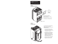
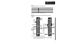
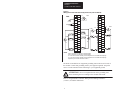
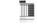
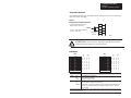
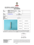
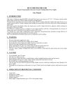
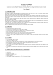
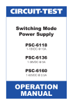
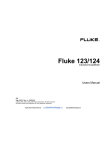
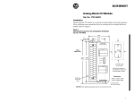
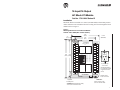
16 Input/16 Output
AC Block I/O Module
Cat. No. 1791-16AC Series B
Installation
Mount the block I/O module in a vertical (recommended) or horizontal position.
Allow sufficient room around the block for cooling air to flow through the block
module. Refer to Figure 1.
Figure 1
Mounting Dimensions for the Block I/O Module
Cat. No. 1791–16AC (PLC version shown)
4.35
(110.5)
3.35
(85.1)
0.5
(12.7)
Inches
(Millimeters)
1791-16AC
30
120V ac IN/OUT
1
IN G
10
11
12
13
14
15
16
17
00
01
02
03
04
05
06
07
6.95
6.60
(176.5) (167.6)
IN
G
00 10
01 11
02 12
03 13
04 14
05 15
06 16
07 17
COMM
STATUS
OUT
G
10
11
12
13
14
15
16
17
Block
00
01
02
03
04
05
06
07
OUT G
30
2.0 (50.8) air gap
on all 4 sides.
10
11
12
13
14
15
16
17
00
01
02
03
04
05
06
07
RACK #
Operating temperature
in air gap below module
must not exceed 60oC
(140oF).
1
ALLENBRADLEY
2 mounting holes
for 1/4–inch screws
Equipment
Grounding Stud
Dimensions
6.95H x 4.35W x 3.85D
(176.5H x 110.5W x 98D)
CAUTION: When tightening grounding
stud nut, do not exceed 15 in-lbs.
1
Installation Instructions
Block I/O
Cat. No. 1791-16AC Series B
Figure 2
Mounting on a DIN Rail
DIN Rail
A-B Pt. No. 199-DR1
46277-3
EN 50022
(35 x 7.5mm)
1. Hook top of slot over DIN rail.
2. While pressing block against rail, pull
down on locking levers.
3. When block is flush against rail, push up
on locking levers to secure block to rail.
Locking levers
Figure 3
Inserting Labels
A set of die-cut labels is supplied with your
module. Select the proper module
designation labels (PLC or SLC) for the front
door and terminal strips.
1. Remove labels from package. Select
correct labels for your application. (PLC
label is numbered 00–07 and 10–17. SLC
is numbered 00–07 and 08–15.)
2. Remove plastic cover on terminal strip
by flexing in middle. Slip the terminal
designation label with power and RIO
designations into built-in holders in left
terminal strip cover. Flex cover slightly
to install. Repeat for the other
terminal strip using the remaining label.
2
3. Open clear front door. Insert module
designation label into slots in door.
3
2
Installation Instructions
Block I/O
Cat. No. 1791-16AC Series B
Table A
Acceptable Wiring Cables for Block I/O Connection
Use
Cable Type
Remote I/O link
Belden 9463
Input and output wiring
Up to 14AWG (2mm2) stranded with 3/64 inch insulation
Connect wiring as shown in Figure 4 or Figure 5.
Figure 4
Wiring Connections with PLC Family Programmable Controllers (refer
to Table B)
PLC
1
1
L1
30
L2/N
30 NO
29
CONN
NOT
USED
NO
CONN
NOT
USED
NOT
USED
NO
CONN NO
L1
2
GND
NOT
USED
N
NOT
USED
BLU
RIO
SHD
CLR COM
COM
1
COM
1
COM
1
in 00
L2/N
in 01
in 02
in 03
L1
in 04
NO
CONN
2
COM
2
COM
2
L2/N
L1–4
out 00
out 11
out 01
out 12
out 02
in 13
out 13
L1
in 15
out 03
out 14
out 04
out 15
out 05
in 16
30
L2/N
out 10
L2/N
in 05
in 06
L1
L1–4
L1–3
in 12
in 14
L1–3
L1–3
in 10
in 11
L1
CONN
L1–4
29
in 17
in 07
30
out 16
out 06
2
1
out 17
out 07
1
NOTE: COM 1 connections are internally connected together.
COM 2 connections are internally connected together.
L1–3 connections must be externally connected together to accommodate total amperage.
L1–4 connections must be externally connected together to accommodate total amperage.
Output fusing is recommended. Refer to Table C.
3
Installation Instructions
Block I/O
Cat. No. 1791-16AC Series B
Figure 5
Wiring Connections with SLC Family Processors (refer to Table B)
1
SLC
2
30
L2/N
L1
GND
NOT
USED
L1
30
1
29
NOT
USED
N
RIO
NOT
USED
in 00
L2/N
in 01
in 02
in 03
L1
in 04
L2/N
L1
L2/N
L1–4
out 08
L2/N
out 00
out 09
out 01
in 10
out 10
out 02
in 11
out 11
L1
in 13
out 03
out 12
out 04
out 13
out 05
in 16
29
in 15
30
L1
L1–4
L1–3
in 05
in 06
L1–4
L1–3
L1–3
in 08
in 12
NO
CONN
NO
CONN
2
COM
2
COM
2
in 09
NOT
USED
NO
CONN
SHD
CLR COM
COM
1
COM
1
COM
1
NO
CONN
NOT
USED
BLU
NO
CONN
in 07
30
out 14
out 06
2
1
out 15
out 07
1
NOTE: COM 1 connections are internally connected together.
COM 2 connections are internally connected together.
L1–3 connections must be externally connected together to accommodate total amperage.
L1–4 connections must be externally connected together to accommodate total amperage.
Output fusing is recommended. Refer to Table C.
The block I/O module has an equipment grounding stud on the lower left side of
the module. Connect this grounding stud to your equipment ground. Torque the
nut to 15 in-lbs maximum when connecting to your equipment ground.
ATTENTION: Do not overtighten the nut on the grounding stud
when connecting the wire. Damage to the module could result.
Refer to “Programmable Controller Wiring and Grounding Guidelines”
(1770-4.1) for further information.
4
Installation Instructions
Block I/O
Cat. No. 1791-16AC Series B
Table B
Wiring Block Designations
1791–16AC Series B
Connector/Terminal
Connections
Designation
Power
Connections
Remote I/O
Connections
Description
Left Conn.
L1
ac hot
1
N
ac neutral
3
GND
Chassis ground
21
BLU
Blue wire – RIO
6
CLR
Clear wire – RIO
8
SHD
Shield – RIO
7
Right Conn.
I/O Connections
Input
(G)6
Output
(G)7
in 00 thru in 07
Input 00 thru 07
16, 18, 20,
22, 24, 26,
28, 30
COM 1
L2/N Input Common
10, 12, 142
COM 2
L2/N Input Common
9, 11, 133
PLC: in 10 thru in 17
SLC: in 08 thru in 15
PLC: Input 10 thru 17
SLC: Input 08 thru 15
15, 17, 19,
21, 23, 25,
27, 29
PLC: out 00 thru 07
SLC: out 00 thru 07
PLC: Output 00 thru 07
SLC: Output 00 thru 07
15, 13, 11,
9, 7, 5, 3, 1
L1–3
L1 output supply
21, 19, 174
PLC: out 10 thru 17
SLC: out 08 thru 15
PLC: Output 10 thru 17
SLC: Output 08 thru 15
16, 14, 12,
10, 8, 6, 4, 2
L1–4
L1 output supply
22, 20, 185
Not used
For internal test only;
not for customer use.
No Conn
No internal connection;
customer can use.
4, 5
29, 27, 26
30, 28, 25,
24, 23
1 Connect chassis ground to equipment grounding stud. These are not internally connected.
2 Terminals 10, 12 and 14 are internally connected together.
3 Terminals 9, 11 and 13 are internally connected together.
4 Terminals 17, 19 and 21 must be externally connected by customer to accommodate total amperage.
5 Terminals 18, 20 and 22 must be externally connected by customer to accommodate total amperage.
6 IN (G) = input module group.
7 OUT (G) = output module group.
5
Installation Instructions
Block I/O
Cat. No. 1791-16AC Series B
Figure 6
Switch Settings
1
Default Switch
Settings = 0
1 2 3 4 5 6 7 8
30
SW2
0
SW2–8
Not used
SW2–7
Not Used
SW2–6
0
1
1
Open cover to
access switches
1 2 3 4 5 6 7 8
SW2–5
30
1
SW1
0
1
Position = 0 Position = 1
End View
ATTENTION: Cycle power to the module after
setting the switches.
Last I/O Group
(PLC-2 only)
Not last rack
Last rack
0
1
SW2–4
0
1
Processor
Restart/Lockout (PRL)
Processor Restart
Processor Lockout
Hold Last State
Reset Outputs
Hold Last State
SW2–3
Set to 0
Communication Rate
SW2–2 SW2–1
Bits/s
0
0
57.6 K
0
1
115.2 K
1
0
230.4 K
1
1
230.4 K
Starting Quarter
Module
SW1–2 SW1–1
Group
0
0
0 (1st)
0
1
2 (2nd)
1
0
4 (3rd)
1
1
6 (4th)
6
Installation Instructions
Block I/O
Cat. No. 1791-16AC Series B
1747-SN
Ra
Rack
Number
1771-SN
Ra
Rack
Number
PLC–2
Ra
Rack
Number
PLC–5
Ra
Rack
Number
PLC–5/250
Ra
Rack
Number
PLC–3
Ra
Rack
Number
8
7
6
5
4
3
Rack 0
Rack 1
Rack 1
Not Valid
Rack 0
Rack 0
0
0
0
0
0
0
Rack 1
Rack 2
Rack 2
Rack 1
Rack 1
Rack 1
0
0
0
0
0
1
Rack 2
Rack 3
Rack 3
Rack 2
Rack 2
Rack 2
0
0
0
0
1
0
Rack 3
Rack 4
Rack 4
Rack 3
Rack 3
Rack 3
0
0
0
0
1
1
Rack 5
Rack 5
Rack 4
Rack 4
Rack 4
0
0
0
1
0
0
Rack 6
Rack 6
Rack 5
Rack 5
Rack 5
0
0
0
1
0
1
Rack 7
Rack 7
Rack 6
Rack 6
Rack 6
0
0
0
1
1
0
Rack 7
Rack 7
Rack 7
0
0
0
1
1
1
Rack 10
Rack 10
Rack 10
0
0
1
0
0
0
Rack 11
Rack 11
Rack 11
0
0
1
0
0
1
Rack 12
Rack 12
Rack 12
0
0
1
0
1
0
Rack 13
Rack 13
Rack 13
0
0
1
0
1
1
Rack 14
Rack 14
Rack 14
0
0
1
1
0
0
Rack 15
Rack 15
Rack 15
0
0
1
1
0
1
Rack 16
Rack 16
Rack 16
0
0
1
1
1
0
Rack 17
Rack 17
Rack 17
0
0
1
1
1
1
Rack 20
Rack 20
Rack 20
0
1
0
0
0
0
Rack 21
Rack 21
Rack 21
0
1
0
0
0
1
Rack 22
Rack 22
Rack 22
0
1
0
0
1
0
Rack 23
Rack 23
Rack 23
0
1
0
0
1
1
Rack 24
Rack 24
Rack 24
0
1
0
1
0
0
Rack 25
Rack 25
Rack 25
0
1
0
1
0
1
Rack 26
Rack 26
Rack 26
0
1
0
1
1
0
Rack 27
Rack 27
Rack 27
0
1
0
1
1
1
Rack 30
Rack 30
0
1
1
0
0
0
Rack 31
Rack 31
0
1
1
0
0
1
Rack 32
Rack 32
0
1
1
0
1
0
Rack 33
Rack 33
0
1
1
0
1
1
Rack 34
Rack 34
0
1
1
1
0
0
Rack 35
Rack 35
0
1
1
1
0
1
Rack 36
Rack 36
0
1
1
1
1
0
Rack 37
Rack 37
0
1
1
1
1
1
Rack 40
1
0
0
0
0
0
Rack 41
1
0
0
0
0
1
Rack 42
1
0
0
0
1
0
Rack 43
1
0
0
0
1
1
Rack 44
1
0
0
1
0
0
Rack 45
1
0
0
1
0
1
Rack 46
1
0
0
1
1
0
Rack 47
1
0
0
1
1
1
Rack 50
1
0
1
0
0
0
SW1 Switch Position
7
Installation Instructions
Block I/O
Cat. No. 1791-16AC Series B
1747-SN
Rack
Number
1771-SN
Rack
Number
PLC–2
Rack
Number
PLC–5
Rack
Number
PLC–5/250
Rack
Number
PLC–3
Rack
Number
8
7
6
5
4
3
Rack 51
1
0
1
0
0
1
Rack 52
1
0
1
0
1
0
Rack 53
1
0
1
0
1
1
Rack 54
1
0
1
1
0
0
Rack 55
1
0
1
1
0
1
Rack 56
1
0
1
1
1
0
Rack 57
1
0
1
1
1
1
Rack 60
1
1
0
0
0
0
Rack 61
1
1
0
0
0
1
Rack 62
1
1
0
0
1
0
Rack 63
1
1
0
0
1
1
Rack 64
1
1
0
1
0
0
Rack 65
1
1
0
1
0
1
Rack 66
1
1
0
1
1
0
Rack 67
1
1
0
1
1
1
Rack 70
1
1
1
0
0
0
Rack 71
1
1
1
0
0
1
Rack 72
1
1
1
0
1
0
Rack 73
1
1
1
0
1
1
Rack 74
1
1
1
1
0
0
Rack 75
1
1
1
1
0
1
Rack 76
1
1
1
1
1
0
Not Valid
1
1
1
1
1
1
SW1 Switch Position
Rack address 77 is an illegal configuration.
PLC-5/11 processors can scan rack 03.
PLC-5/15 and PLC-5/20 processors can scan racks 01–03.
PLC-5/25 and PLC-5/30 processors can scan racks 01–07.
PLC-5/40 and PLC-5/40L processors can scan racks 01–17.
PLC-5/60 and PLC-5/60L processors can scan racks 01–27.
PLC-5/250 processors can scan racks 00–37.
The SLC 500 controllers communicate with the block I/O using an I/O Scanner
module (cat. no. 1747-SN series A). Refer to the user manual for the 1747-SN/A
Scanner module for more information.
Important: This block I/O module is not compatible with the 1747-DSN
Distributed I/O Scanner module.
8
Installation Instructions
Block I/O
Cat. No. 1791-16AC Series B
Termination Resistor
A termination resistor must be installed on the last block in a series. Connect the
resistor as shown in Figure 7.
Figure 7
Installing the Termination Resistor
Connect termination resistor across
terminals 6 (BLU) and 8 (CLR).
BLU
CLR
150 ohm – 57.6K and 115.2K baud
82 ohm – 230.4K baud
SHD
Termination
Resistor
10835–I
ATTENTION: Devices that are operating at 230.4K baud must have
82 ohm terminators in place for proper operation.
Indicators
PLC
SLC
IN
COMM
00
01
02
03
04
05
06
07
G
10
11
12
13
14
15
16
17
IN
OUT
00
01
02
03
04
05
06
07
G
10
11
12
13
14
15
16
17
STATUS
COMM
00
01
02
03
04
05
06
07
G
08
09
10
11
12
13
14
15
OUT
00
01
02
03
04
05
06
07
G
08
09
10
11
12
13
14
15
STATUS
Indicator
Description
COMM
OFF
ON
Flashing
Communication not established
Communication established
Processor in Program mode
STATUS
OFF
ON
Flashing
Normal
Error (hardware or software), block power low
COMM FAIL – communication cable disconnected, 100ms between valid frames, no
more than 255 valid frames between valid frames addressed to block, 20ms idle
time exceeded.
COMM and STATUS will alternately flash when processor restart lockout is selected, a fault has occurred and the processor
is communicating with the block.
9
Installation Instructions
Block I/O
Cat. No. 1791-16AC Series B
Fusing
The block I/O module is internally fused to protect the module. No external
power fusing is required.
The outputs of the block I/O modules are not fused. Fusing of outputs is
recommended. If desired to fuse an output, you must provide external fusing.
Table C
Recommended Fuses
Type of
Circuit
ac
Part Number1
Size
Rating in
Amps
Maximum Surge Current2
(repeatable every 2s)
SAN-O SS2-1.0
0.25 in. x 1.25 in.
1.0A
3.0A for 50ms
SAN-O MQ2-1.0
5mm x 20mm
1.0A
2.5A for 50ms
1 Note: Do not substitute another fuse for those listed.
2 The recommended fuses will withstand surges of the above listed currents for the time specified..
Block I/O modules are derated linearly above 30oC up to and including 60oC.
Table D
Output Ratings and Non-fused Surge Currents
Catalog
Number
1791-16AC/B
Mounting
120V ac
Vertical
600mA
300mA
120V ac
Horizontal
300mA
150mA
1 These surge ratings are for non–fused outputs only.
10
Max. Output Rating:
@ 60oC
@ 30oC
Voltage
Maximum Surge Current1
(repeatable every 2s)
10A for 50ms
Installation Instructions
Block I/O
Cat. No. 1791-16AC Series B
1791-16AC Specifications
Input Specifications
Inputs per Block
16 (2 groups of 8)
Nominal Input Current
11mA
Nominal Input Voltage
120V ac
On-state Voltage Range
79–132V ac, 47–63Hz
Off-state Voltage
Maximum
35V
On-state Current
Minimum
Maximum
5mA @ 79V, 60Hz
12.3mA @ 132V, 60Hz
Off-state Current
Minimum
2.3mA (60Hz)
Input Impedance
Maximum
15K ohms @ 60Hz
Input Signal Delay
Off to on
On to off
1.0ms
26ms (maximum) (allows for 1/2
cycle drop-out)
Output Specifications
Outputs per Block
16 (2 groups of 8)
Output Voltage Range
20–132V ac
Output Current Rating
Vertical Mtg.
Horizontal Mtg.
300mA @ 60oC, 600mA @ 30oC
150mA @ 60oC, 300mA @ 30oC
Surge Current
10A for 50ms each,
repeatable every 2 sec.
Minimum On-state Current
50mA per output
Maximum On-state Voltage Drop
1.5V peak @ 300mA
Off-state Leakage Current (maximum) 3mA
Output Signal Delay Off to on
On to off
1.0ms @ 60Hz; 1.0ms @ 50Hz
8.3ms @ 60Hz; 10.0ms @ 50Hz
Specifications continued on next page
11
Installation Instructions
Block I/O
Cat. No. 1791-16AC Series B
General Specifications
External Power (internally protected no external fuse required)
Voltage
Current
Dimensions
Inches
Millimeters
85–132V ac, 47–63Hz
150mA
6.95H X 4.35W X 3.85D
176.5H X 110.5W X 98D
Isolation Power supply to RIO
I/O Group-to-Group
I/O Group-to-Logic
500V ac
1250V ac
1250V ac
Power Dissipation
Maximum
22.76 Watts
Thermal Dissipation Maximum
77.6 BTU/hr
Environmental Conditions
Operational Temperature
Storage Temperature
Relative Humidity
0 to 60oC (32 to 140oF)
–40 to 85oC (–40 to 185oF)
5 to 95% noncondensing
Conductors
Wire Size
Category
14 gauge stranded maximum
3/64 inch insulation maximum
11
1 You use this conductor category information for planning conductor routing as described in the
system level installation manual.
WORLD HEADQUARTERS
Allen-Bradley
1201 South Second Street
Milwaukee, WI 53204 USA
Tel: (414) 382-2000
Telex: 43 11 016
FAX: (414) 382-4444
With offices in major cities worldwide
Publication 1791-2.15 – March 1994
Supersedes publication 1791-2.15 – April 1993
12
PN 955117–19
Copyright 1994 Allen-Bradley Company, Inc. Printed in USA