1
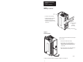
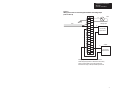
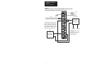
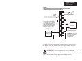
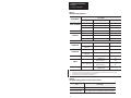
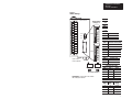
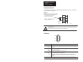
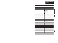
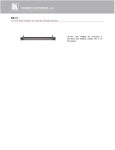
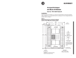
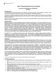
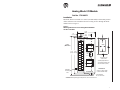
Analog Block I/O Module
Cat. No. 1791-N4C2
Installation
Mount the block I/O module in a vertical (recommended) or horizontal position.
Allow sufficient room around the block for cooling air flow through the block
module. Refer to Figure 1.
Figure 1
Mounting Dimensions for the Analog Block I/O Module
Cat. No. 1791-N4C2
2.710
(68.8)
1.71
(43.4)
0.5
(12.7)
1791-N4C2
1
ANALOG BLOCK
OUTPUT
Inches
(Millimeters)
Block
0
1
6.95
6.60
(176.5) (167.6)
POWER
COMM
FAULT
2.0 (50.8) air gap
on all 4 sides.
INPUT
0
Operating temperature in
air gap below module must
not exceed 60oC (140oF).
1
2
3
Dimensions
Equipment
Grounding
Stud
30
6.95H x 2.710W x 3.85D
(176.5H x 68.8W x 98D)
ALLENBRADLEY
2 mounting holes
for 1/4–inch screws
CAUTION: When tightening grounding stud nut, do not exceed 15 in-lbs.
1
Installation Instructions
Block I/O
Cat. No. 1791-N4C2
Figure 2
Mounting on a DIN Rail
Block
1. Hook top of slot over DIN rail.
2. While pressing block against rail,
pull down on locking lever.
3. When block is flush against rail,
push up on locking lever to secure
block to rail.
DIN Rail
A-B Pt. No. 199-DR1
46277-3
EN 50022
(35 x 7.5mm)
Locking Lever
12382–I
Figure 3
Inserting Labels
Labels for the front door and terminal strip are supplied
with your module.
1. Remove die-cut labels from package.
2. Remove plastic cover on terminal strip by
flexing in middle. Slip terminal designation label
into built-in holders in terminal strip cover. Flex
cover to install.
3. Open clear front door. Insert module designation
label into slots that secure it to the door.
2
3
12383–I
Connect wiring as shown in Figure 4, Figure 5 or Figure 6.
2
Installation Instructions
Block I/O
Cat. No. 1791-N4C2
Figure 4
Wiring Connections for the Analog Block Module with Voltage Input
(refer to Table A)
1
GND
RIO
NOT
USED
N
NOT
USED
BLU
SHD
CLR
RET
in0
GND
in0
RET
in1
+
User Analog
Input Device
in I0
in V1
in I1
in V2
GND
in2
RET
in3
in V3
RET
out1
Voltage Input
in V0
GND
in1
RET
in2
GND
in3
RET
out0
L2/N
L1
L1
–
in I2
in I3
+24
Vdc
out0
Output
+
User Analog
Output Device
out1
NOT
USED
30
–
Analog signals must be within the +10V common
mode voltage range which is referenced to the analog
system common (GND). If an input channel floats
outside of this range, invalid input readings will result.
3
Installation Instructions
Block I/O
Cat. No. 1791-N4C2
Figure 5
Wiring Connections for the Analog Block Module with Current Input
and Customer-Supplied Loop Power (refer to Table A)
1
GND
NOT
USED
RIO
N
NOT
USED
BLU
SHD
CLR
RET
in0
Analog signals must be within the
+10V common mode voltage range
which is referenced to the analog
system common (GND). If an input
channel floats outside of this range,
invalid input readings will result.
Output
–
User Analog
Output Device
+
GND
in1
RET
in2
in V2
GND
in2
RET
in3
in V3
NOT
USED
30
4
User Analog
Input Device
in I0
in V1
RET
out1
Current Input
+
in V0
GND
in0
RET
in1
GND
in3
RET
out0
L2/N
L1
L1
in I1
–
in I2
in I3
+24
Vdc
out0
out1
User +24V
User GND
ATTENTION: The 249 ohm
input current shunt is rated
at 0.25 Watts. Do not
exceed this rating.
Installation Instructions
Block I/O
Cat. No. 1791-N4C2
Figure 6
Wiring Connections for the Analog Block Module with Current Input
and Block-Supplied Loop Power (refer to Table A)
1
GND
NOT
USED
RIO
L2/N
L1
L1
N
NOT
USED
BLU
SHD
CLR
RET
in0
Analog signals must be within the
+10V common mode voltage range
which is referenced to the analog
system common (GND). If an input
channel floats outside of this range,
invalid input readings will result.
Output
–
User Analog
Output Device
in V1
GND
in1
RET
in2
in V2
GND
in2
RET
in3
in V3
GND
in3
RET
out0
NOT
USED
30
Loop Powered
Current Input
in I0
GND
in0
RET
in1
RET
out1
+
in V0
in I1
in I2
in I3
+24
Vdc
out0
out1
i
i
User Analog
Input Device
+24V loop power supplied
from terminal 25 on block.
ATTENTION: The 249 ohm
input current shunt is rated
at 0.25 Watts. Do not
exceed this rating.
The block I/O module has an equipment grounding stud on the lower left side of
the module. Connect this grounding stud to your equipment ground. Torque the
nut to 15 in-lbs maximum when connecting to your equipment ground.
ATTENTION: Do not overtighten the nut on the grounding stud
when connecting the wire. Damage to the module could result.
Refer to “Programmable Controller Wiring and Grounding Guidelines”
(1770-4.1) for further information.
5
Installation Instructions
Block I/O
Cat. No. 1791-N4C2
Table A
Wiring Block Designations
1791–N4C2
Connections
C
ti s
Power Connections
Designation
Description
Terminal No.
L1
ac hot
1
N
ac neutral
3
Chassis ground
21
GND
Transducer Power2
+24V
For current input only
25
Remote I/O
Connections
BLU
Blue wire – RIO
6
CLR
Clear wire – RIO
8
SHD
Shield – RIO
7
I/O Connections
inV0 thru inV3
Voltage Input 0 through 3
9, 13, 17, 21
Voltage Input
RET in0 thru
RET in3
Input Return 0 through 3
10, 14, 18, 22
inI0 thru inI3
Current Input 0 through 3
11, 15, 19, 23
Current Input
RET in0 thru
RET in3
Input Return 0 through 3
10, 14, 18, 22
Input Ground
GNDin0–GNDin3
Channels 0–3 ground
12, 16, 20, 243
out 0 – RET out 0
Output 0 (+)
Return output 0 (–)
27
264
out 1 – RET out 1
Output 1 (+)
Return output 1 (–)
29
284
Not used
For internal test only; not for
customer use.
4, 5, 30
Output
1
2
3
4
Connect chassis ground to equipment grounding stud. These are not internally connected.
20-28V dc (nominal 24V, 100mA) voltage source for accommodating loop-powered current transducer inputs.
Terminals 12, 16, 20, and 24 are internally connected together.
Terminals 26 and 28 are internally connected together.
Table B
Acceptable Wiring Cables for Block I/O Connection
Use
Cable Type
Remote I/O link
Belden 9463
Input and output wiring
Up to 14AWG (2mm2) stranded with 3/64 inch insulation
6
Installation Instructions
Block I/O
Cat. No. 1791-N4C2
Figure 7
Switch Settings
1791-N4C2
POWER
Default Switch
Settings = 0
1 2 3 4 5 6 7 8
ANALOG BLOCK
1
SW2
COMM
FAULT
SW1
30
Open cover to
access switches
0
Position = 0
1
Position = 1
End View of Switch
ATTENTION: Cycle power to the module
after setting the switches.
SW2–7
Not
Used
SW2–6
0
1
SW2–5
1
1 2 3 4 5 6 7 8
0
SW2–8
Not
used
0
1
Last I/O Group
Not last rack
Last rack
Processor
Restart/Lockout (PRL)
Processor Restart
Processor Lockout
SW2–4
0
1
Hold Last State
Reset Outputs
Hold Last State
SW2–3
0
1
Transfer Type
Block Transfer
Discrete Transfer
Communication Rate
SW2–2 SW2–1
Bits/s
0
0
57.6 K
0
1
115.2 K
1
0
230.4 K
1
1
230.4 K
Starting Quarter
Module
SW1–2 SW1–1
Group
0
0
0 (1st)
0
1
2 (2nd)
1
0
4 (3rd)
1
1
6 (4th)
7
Installation Instructions
Block I/O
Cat. No. 1791-N4C2
1747-SN
R
Rack
Number
1771-SN
R
Rack
Number
PLC–2
R
Rack
Number
PLC–5
R
Rack
Number
PLC–5/250
R
Rack
Number
PLC–3
R
Rack
Number
8
7
6
5
4
3
Rack 0
Rack 1
Rack 1
Not Valid
Rack 0
Rack 0
0
0
0
0
0
0
Rack 1
Rack 2
Rack 2
Rack 1
Rack 1
Rack 1
0
0
0
0
0
1
Rack 2
Rack 3
Rack 3
Rack 2
Rack 2
Rack 2
0
0
0
0
1
0
Rack 3
Rack 4
Rack 4
Rack 3
Rack 3
Rack 3
0
0
0
0
1
1
Rack 5
Rack 5
Rack 4
Rack 4
Rack 4
0
0
0
1
0
0
Rack 6
Rack 6
Rack 5
Rack 5
Rack 5
0
0
0
1
0
1
Rack 7
Rack 7
Rack 6
Rack 6
Rack 6
0
0
0
1
1
0
Rack 7
Rack 7
Rack 7
0
0
0
1
1
1
Rack 10
Rack 10
Rack 10
0
0
1
0
0
0
Rack 11
Rack 11
Rack 11
0
0
1
0
0
1
Rack 12
Rack 12
Rack 12
0
0
1
0
1
0
Rack 13
Rack 13
Rack 13
0
0
1
0
1
1
Rack 14
Rack 14
Rack 14
0
0
1
1
0
0
Rack 15
Rack 15
Rack 15
0
0
1
1
0
1
Rack 16
Rack 16
Rack 16
0
0
1
1
1
0
Rack 17
Rack 17
Rack 17
0
0
1
1
1
1
Rack 20
Rack 20
Rack 20
0
1
0
0
0
0
Rack 21
Rack 21
Rack 21
0
1
0
0
0
1
Rack 22
Rack 22
Rack 22
0
1
0
0
1
0
Rack 23
Rack 23
Rack 23
0
1
0
0
1
1
Rack 24
Rack 24
Rack 24
0
1
0
1
0
0
Rack 25
Rack 25
Rack 25
0
1
0
1
0
1
Rack 26
Rack 26
Rack 26
0
1
0
1
1
0
Rack 27
Rack 27
Rack 27
0
1
0
1
1
1
Rack 30
Rack 30
0
1
1
0
0
0
Rack 31
Rack 31
0
1
1
0
0
1
Rack 32
Rack 32
0
1
1
0
1
0
Rack 33
Rack 33
0
1
1
0
1
1
Rack 34
Rack 34
0
1
1
1
0
0
Rack 35
Rack 35
0
1
1
1
0
1
Rack 36
Rack 36
0
1
1
1
1
0
Rack 37
Rack 37
0
1
1
1
1
1
Rack 40
1
0
0
0
0
0
Rack 41
1
0
0
0
0
1
Rack 42
1
0
0
0
1
0
Rack 43
1
0
0
0
1
1
Rack 44
1
0
0
1
0
0
Rack 45
1
0
0
1
0
1
Rack 46
1
0
0
1
1
0
Rack 47
1
0
0
1
1
1
Rack 50
1
0
1
0
0
0
8
SW1 Switch Position
Installation Instructions
Block I/O
Cat. No. 1791-N4C2
1747-SN
Rack
Number
1771-SN
Rack
Number
PLC–2
Rack
Number
PLC–5
Rack
Number
PLC–5/250
Rack
Number
PLC–3
Rack
Number
8
7
6
5
4
3
Rack 51
1
0
1
0
0
1
Rack 52
1
0
1
0
1
0
Rack 53
1
0
1
0
1
1
Rack 54
1
0
1
1
0
0
Rack 55
1
0
1
1
0
1
Rack 56
1
0
1
1
1
0
Rack 57
1
0
1
1
1
1
Rack 60
1
1
0
0
0
0
Rack 61
1
1
0
0
0
1
Rack 62
1
1
0
0
1
0
Rack 63
1
1
0
0
1
1
Rack 64
1
1
0
1
0
0
Rack 65
1
1
0
1
0
1
Rack 66
1
1
0
1
1
0
Rack 67
1
1
0
1
1
1
Rack 70
1
1
1
0
0
0
Rack 71
1
1
1
0
0
1
Rack 72
1
1
1
0
1
0
Rack 73
1
1
1
0
1
1
Rack 74
1
1
1
1
0
0
Rack 75
1
1
1
1
0
1
Rack 76
1
1
1
1
1
0
Not Valid
1
1
1
1
1
1
SW1 Switch Position
Rack address 77 is an illegal configuration.
PLC-5/11 processors can scan rack 03.
PLC-5/15 and PLC-5/20 processors can scan racks 01–03.
PLC-5/25 and PLC-5/30 processors can scan racks 01–07.
PLC-5/40 and PLC-5/40L processors can scan racks 01–17.
PLC-5/60 and PLC-5/60L processors can scan racks 01–27.
PLC-5/250 processors can scan racks 00–37.
The SLC 500 controllers communicate with the block I/O using an I/O Scanner
module (cat. no. 1747-SN series A). Refer to the user manual for the 1747-SN/A
Scanner module for more information.
Note: This block I/O module is not compatible with the 1747-DSN Distributed
I/O Scanner module.
9
Installation Instructions
Block I/O
Cat. No. 1791-N4C2
Termination Resistor
A termination resistor must be installed on the last block in a series. Connect the
resistor as shown in Figure 8.
Figure 8
Installing the Termination Resistor
Connect termination resistor across
terminals 6 (BLU) and 8 (CLR).
BLU
150 ohm – 57.6K and 115.2K baud
82 ohm – 230.4K baud
CLR
SHD
Termination
Resistor
10835–I
ATTENTION: Devices that are operating at 230.4K baud must have
82 ohm terminators in place for proper operation.
Indicators
POWER
COMM
FAULT
Indication
Description
Power
OFF
ON
No power
Power okay
COMM
OFF
ON
Flashing
Communication not established
Communication established
Reset commands being received in Program mode
FAULT
OFF
ON
Flashing
Normal
Error (hardware or software), block power low
COMM FAIL – remote I/O wire disconnected, 100ms between valid frames, no more
than 255 valid frames between valid frames addressed to block, 20ms idle time
exceeded.
COMM and FAULT will alternately flash when processor restart lockout is selected, a fault has occurred and the processor is
communicating with the block.
10
Installation Instructions
Block I/O
Cat. No. 1791-N4C2
1791-N4C2 Specifications
Input Specifications
Inputs per Block
4 Selectable
Type of Input
+10V (14 bit)
+5V (14 bit)
0–10V (14 bit)
0–5V (14 bit)
0–20mA (14 bit)
+20mA (14 bit)
Update Rate per Channel
108ms
Input Impedance
Voltage: 10 megohm
Current: 249 ohm
Absolute Accuracy
0.1% @ 25oC
Linearity
0.05% @ 25oC
Common Mode Rejection
–75db
Normal Mode Rejection
–18db @ 50Hz
–20db @ 60Hz
Output Specifications
Outputs per Block
2
Output Current Range
0–20mA (13 bits)
Output Impedance
Greater than 1 megohm
Internal Update Rate per Channel
10ms
Drive Capability
20mA into loads of 1K ohms or less
Short Circuit Protection
Indefinite
Absolute Accuracy
0.1% @ 25oC
Linearity
0.05% @ 25oC (over 4-20mA range)
Overall Accuracy Drift
75 ppm/oC
Specifications continued on next page
11
Installation Instructions
Block I/O
Cat. No. 1791-N4C2
1791-N4C2 Specifications
General Specifications
Number of Channels Input
Output
4
2
Resolution
14 bits full scale inputs
13 bits full scale outputs
Input Band Width
5Hz
Overvoltage Protection
Input
Output
ATTENTION: The 249 ohm input
current shunt is rated at 0.25 Watts.
Do not exceed this rating.
140V ac
140V ac
External Power
Voltage
Current
85–132V ac, 47–63Hz
150mA
Dimensions
Inches
Millimeters
6.95H X 2.7W X 3.85D
176.5H X 68.8W X 98D
Isolation Inputs to Outputs
Power and Chassis to I/O
RIO and Chassis to world
500V ac
1000V ac
1000V ac
Power Dissipation
16.9 Watts
Maximum
Thermal Dissipation Maximum
57.63 BTU/hr
Environmental Conditions
Operational Temperature
Storage Temperature
Relative Humidity
0 to 60oC (32 to 140oF)
–40 to 85oC (–40 to 185oF)
5 to 95% noncondensing
Conductors
14 gauge (2mm2) stranded maximum
3/64 inch insulation maximum
11
Wire Size
Category
1 You use this conductor category information for planning conductor routing as described in the
system level installation manual.
WORLD HEADQUARTERS
Allen-Bradley
1201 South Second Street
Milwaukee, WI 53204 USA
Tel: (414) 382-2000
Telex: 43 11 016
FAX: (414) 382-4444
With offices in major cities worldwide
Publication 1791-2.12 – March 1994
Supersedes publication 1791-2.12 – December 1992
12
PN 955117–58
Copyright 1994 Allen-Bradley Company, Inc. Printed in USA