1
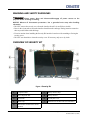
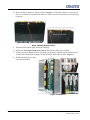
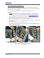
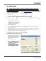
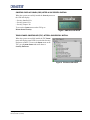
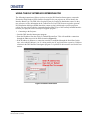
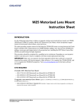
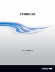
Security Kit Interface Board
Instruction Sheet
INTRODUCTION
Use the following instructions when installing the Security Kit interface board in CP2000/M/MR,
CP2000-h/i, S/SB, X/XB and CP2000-ZX models. The purpose of the Security Kit is to ensure the
content on the interface board is protected. Image decryption keys on the Security Kit interface board
are erased if it is tampered with in any way. The Security Kit interface board is constantly monitored
even when it is not installed in a projector.
SECURITY KIT PART NUMBERS
All previous boards have been upgraded to the new Gore enclosure, which contains the glue cable.
They are all now Type 5 boards.
Security Kit Part
Number
Description
003-120460-05
NEW HDCP-1TK SEC Kit “Glue Cable board” (Type 5
004-120460-05
Refurb HDCP-1TK SEC Kit “Glue Cable board” (Type 5)
004-120383-11
Upgrade SEC Kit - 1CP (HDCP) “Glue Cable board” (Formerly Type 4)
004-100031-11
Upgrade SEC Kit -1SR (Secure Ready) “Glue Cable board” (Formerly Type 2)
004-100170-11
Upgraded SEC Kit -1S (Upgraded 1SR) (Secure) “Glue Cable board”
(Formally Type 3)
004-100171-11
Upgraded SEC Kit -1RH (RoHS Hybrid) (Formally Type 3)
004-100119-11
Upgraded SEC Kit - 1R (RoHS) “Glue Cable board” (Formally Type 3)
NOTE: Type 2, 3 and 4 listed above have been upgraded to security kit.
Security Kit Interface Board Instruction Sheet
020-100300-04 Rev. 1 (10-2010)
1 of 10
WARNING AND SAFETY GUIDELINES
WARNING Always power down and disconnect/disengage all power sources to the
projector before servicing or cleaning.
NOTICE: Observe all electrostatic precautions. Use a grounded wrist strap when handling
electronics.
• DO NOT remove the security cover from the interface board. It is not field serviceable.
• Press in the ejector tabs to insert the interface board from the cardcage. During insertion ensure the
tabs are pressed inline with the hinge.
• Exercise caution when installing the Security Kit interface board to avoid scratching or flexing the
security cover.
• DO NOT use chemicals to clean the security cover. If necessary, only use a dry cloth.
OVERVIEW OF SECURITY KIT
Figure 1 Security Kit
2 of 10
A
Component Side
F
Battery Harness Tape
B
Non-component Side
G
Battery Harness
C
Ejector Tab
H
Security Kit Cover
D
Metal Clips
I
Manufacturer and Electronic Serial Numbers
E
Manufacturer and Electronic Serial
Numbers
Security Kit Interface Board Instruction Sheet
020-100300-04 Rev. 1 (10-2010)
INSTRUCTIONS
Make sure you have read and understood all instructions before handling and installing the Security
Kit Interface Board.
UNPACKING
WARNING! Remove all hand jewelry before handling the board. Ensure all packaging
is saved for shipping non-secured interface boards back to the factory.
INSTALLATION
FOR CP2000-ZX, CP2000-M/MR MODELS ONLY
1. BEFORE removing the non-secure interface board, upgrade the
DLP® projector software to v14.2.50 (or higher). This is required to
run the projector with the new Security Kit interface board. PCM 3.0
(or higher) is mandatory to ensure the proper status reports are
logged. For software upgrade instructions, refer to Software
Upgrade, on page 6.Remove the PCM cover, unlock and remove the
projector’s front lid and remove the PCM PCB.
2. Wearing a grounded wrist strap, remove the non-secure interface
board. First release the ejector tabs on board, then gently pull on the
tabs to remove the board slightly from the cardcage. Handling the
board along its taped edges only, carefully remove it from the
cardcage and place it into a protective ESD sleeve. (Figure 2).
NOTE: Pack the non-secure board using the shipping material that Figure 2 Board Removal
came with the new board. Send it back to the factory according to
standard RMA procedures.
3. Following the safe handling details provided in the Warning and Safety Guidelines section,
remove the Security Kit interface board from its packaging. NOTE: Record the Manufacturers
Serial Number (MSN), Electronic Serial Number (ESN) of the board, and the serial number of the
projection head. These numbers must be added to the Network Operator Center (NOC) ticket call
log.
Security Kit Interface Board Instruction Sheet
020-100300-04 Rev. 1 (10-2010)
3 of 10
4. Ensure the battery harness is routed, as shown in Figure 3. If the battery harness is not routed in
this way, coil the wire and position the harness as shown, and secure the harness to the metal clips
using tape.
Figure 3 Routing Battery Harness
5. Align the board with the guide rails in the cardcage.
6. Push on the outer edge of both ejector tabs to fully seat the board in the cardcage.
7. Visually inspect the alignment of the ejector tabs on the newly installed security interface board
with the other boards in the cardcage. All tabs should be flush with each other. (Figure 4)
8. Reinstall the PCM cover, front
lid and the PCM PCB.
Figure 4 Install Board
4 of 10
Security Kit Interface Board Instruction Sheet
020-100300-04 Rev. 1 (10-2010)
FOR CP2000-h,i,S/SB,X/XB MODELS ONLY
Installing the Security Kit interface board in CP2000-h, i, S/SB, X/XB models is similar to the
procedure for the CP2000-ZX, with the only difference being the cardcage is accessed from the top of
the projector instead of the operator side.
Refer to Installation for CP2000-ZX for complete installation/handling instructions.
In general,
1. BEFORE removing the non-secure interface board, upgrade the DLP® projector software to
v14.2.50 (or higher). Install TPC 2.9 (or higher). This is mandatory to ensure the proper status
reports are logged. For software upgrade instructions, refer to Software Upgrade, on page 6
2. Remove the light engine lid and cardcage lid. Refer to the CP2000 Service Manual.
3. Wearing a grounded wrist strap, remove the existing non-secure interface board. Handling the
board along its taped edges only, place it into a protective ESD sleeve.
4. Hold the Security Kit interface board from both the ejector tabs and insert into the cardcage guide
rails (Figure 5, #1).
5. Carefully, slide the board into the cardcage (Figure 5, #2).
6. Press on both ejector tabs until the board is properly seated in the cardcage (Figure 5, #3). Ensure
the tabs are inline with the hinges.
7. Replace the light engine lid and cardcage lid.
Line-up with guide rails
Slide into cardcage
Seat board in cardcage
Figure 5 Install Security Kit Interface Board
Security Kit Interface Board Instruction Sheet
020-100300-04 Rev. 1 (10-2010)
5 of 10
SOFTWARE UPGRADE
DLP® Software v14.2.50 (or higher) is required to run the projector with the Security Kit
Interface Board. TPC 2.9 (or higher) and PCM 3.0 (or higher) are mandatory to ensure the
proper status reports are logged. For details, contact Christie Technical Support (1-800-221-8025).
For the most current listings, refer to the website at www.christiedigital.com, click on the Contact Us
tab and select Technical Support.
To upgrade projector software to v14.2.50 or higher:
1. Power-up the projector.
2. Open DLP Cinema® Firmware Installation Program V3.01(28) or higher.
3. Enter the projector’s IP Address and connect via the Ethernet Port. NOTE: Default IP Addressing
for the Security Kit as follows:
• IP Address: 192.168.100.2
• Subnet Mask: 255.255.255.0
• Default Gateway: 192.168.100.1
• DNS Server: 192.168.100.1
4. Log on to the projector.
5. Click Select Release Installation File, locate the Release 14 (or higher) folder and select the
Release.dlpcinema file.
6. Confirm the correct release version is displayed in the window installation program; click the
Start Auto-Install button to begin the installation. This process could take several minutes.
7. Exit the DLP Cinema® Firmware Installation Program.
8. Reset the IP address. For details, refer to the User Manual.
CONFIRMING A SUCCESSFUL INSTALL
1. Open the latest DLP Cinema® Control Program.Enter the projector’s
IP Address and connect via the
Ethernet Port.
2. Log on to the projector.
3. Click the Sys-Status tab and check
the Status window (Figure 6) for
the following entries:
• Security Enclosure Present
• Security Enclosure Armed
Figure 6 Status Window - Successful Install Messages
6 of 10
Security Kit Interface Board Instruction Sheet
020-100300-04 Rev. 1 (10-2010)
CONTROL DISPLAY PANEL (CDP) AFTER A SUCCESSFUL INSTALL
When the system successfully installs the Security menu on
the CDP will display:
• Security Installed: Yes
• Security Armed: Yes
• Security Tamper: No
To access the System menu on the CDP go to
Menu>Status>Security.
Figure 7 CDP Successful Install
TOUCH PANEL CONTROLLER (TPC) AFTER A SUCCESSFUL INSTALL
When the system successfully installs the TPC Status
menu will display green LEDs for each of the Security
Enclosure variables. To access the Status menu on the
TPC, go to System>Status and scroll down to
Security Enclosure.
Figure 8 TPC Successful Install
Security Kit Interface Board Instruction Sheet
020-100300-04 Rev. 1 (10-2010)
7 of 10
UNSUCCESSFUL INSTALL - TAMPERED SECURITY KIT
If installation was unsuccessful and a tamper is detected, it is recommended you record the Electronic
Serial Number from the security kit and contact Christie Technical Support for further action. You may
also install a new Security Kit interface board if available. If a board is not available at the time,
reinstall the existing non-secure interface board and replace it once a new Security Kit interface board
is available.
You will see the following messages if there has been a tamper.
• Security Enclosure Tampered Messages
In the Sys-Status window the following
message appears if the security enclosure
has been tampered (Figure 9).
Figure 9 System Status - Tamper Messages
• Security Enclosure Tamper Detected
When the system detects a tampered Security Kit, the image
shown in Figure 10 is projected on screen when playing
secured content.
Figure 10 CineLink Snow
CONTROL DISPLAY PANEL (CDP) WHEN TAMPER DETECTED
When a tampered Security Kit is detected the CDP displays
Security Tamper Yes (Figure 11).
Figure 11 CDP Security Menu
8 of 10
Security Kit Interface Board Instruction Sheet
020-100300-04 Rev. 1 (10-2010)
USING THE DLP INTERFACE INTERROGATOR
The following instructions will show you how to use the DLP Interface Interrogator to extract the
Electronics Serial Number (ESN) from the Security Kit for your projector as well as identify the
Interface Board Type. The ESN of the Security Kit may be required by distribution sources so they
may reference security information in the Trusted Device Lists (TDL) that are required to generate
Key Distribution Messages (KDM) that allow content to play back through a specific projection
system. You may also be asked to extract the Interface Board Type of the currently installed Interface
board in your projector for the Security Kit Upgrade program.
1. Connecting to the Projector
• Load the DLP Interface Interrogator program.
• Enter the IP address first, then click on ‘Default Ethernet Port’. This will establish a connection
through the Ethernet port of the DLP electronics (Figure 12).
• If the IP address is unknown, a connection can also be established through the Serial Port. In this
case, select which COM port (1 or 2) is being used by the PC and click on the respective COM port
selection in the DLP Interface Interrogator program. A 9-pin RS232 cable must be used for this connection
Figure 12 Ethernet Connection
Security Kit Interface Board Instruction Sheet
020-100300-04 Rev. 1 (10-2010)
9 of 10
2. Logging In to the Interrogator
Once a connection is established in Step 1, simply connect on the ‘Login’ button. Do not modify the
login credentials as they are already pre-set (Figure 13).
Figure 13 Interrogator Login
3. Extracting ESN and Interface Board Type
Once the Login is complete, all the Version and Serial Number information should be populated in the
dialog windows. See Figure 14 for ESN and Interface Board type information.
Figure 14 Board Information
10 of 10
Security Kit Interface Board Instruction Sheet
020-100300-04 Rev. 1 (10-2010)