1
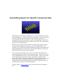
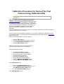
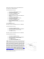
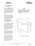
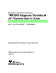
User Manual For Surface Mount Chip Component Test Fixture -- Series-Thru Configuration Test Fixture Overview Surface Mount chip capacitors (single or multi-layered), inductors or resistors can be measured on Inter-Continental Microwave's (ICM) Surface Mount Chip Component Test Fixture. The Test Fixture is designed as a solution for making measurements in a Series-Thru test configuration. Input and output launches are on Microstrip lines. (Customer determines what type of Microstrip is used, 25 mil Alumina is standard.) Adjustable guides on the fixture ensure accurate and repeatable placement of the chip. Deembedding with TRL / LRM or TOSL Calibration Standards removes the effect of the test fixture from your measurements. For custom sized devices, please contact the factory . Electrical Specifications SPECIFICATIONS: For Surface Mount Chip Component Test Fixtures: (25 mil Alumina Substrate) Type of RF Connector on Bolt-On Transition: APC-7 APC-3.5mm (f) Super SMA DC - 18 GHz DC - 26.5 GHz DC - 26.5 GHz Insertion Loss (each Transition): Uncalibrated < 0.5 dB < 0.5 dB < 0.5 dB Return Loss (each Transition): Uncalibrated > 20 dB > 20 dB > 20 dB Isolation: Uncalibrated, Typ. @ 18 GHz > 30 dB > 30 dB > 30 dB Room Temp (25 °C) Room Temp (25 °C) -55 °C to +125 °C Frequency Range: Temperature Range: Configuring Fixture for Specific Component Size When configuring the Test Fixture for a Specific Component Size (such as an 0805) there are only two things you need to do: Select and install the correct spacer (0805 size) Position the guides to fit the new component After doing each of these steps you are ready to begin testing your components! Assembling Spacer for Specific Component Size When testing a new specific component size, you need to select the correct corresponding spacer. This ensures that the component will make contact at the correct area on the microstrip line of the launches. If this is not accomplished, the reference planes set up by the calibration kit will be at a different location than where the dut leads are touching. This will introduce errors into your measurements. With the spacers and screwdrivers there is a small, nickel plated tool that has the slots that match up to the spacers for each component size. For example, if you wanted to test 0805 components, use the tool slot that reads 0805 and match that up to the spacer with the same thickness. (The spacer should slide into the slot of the tool snuggly.) After you have selected the correct spacer, you need to disassemble the fixture and replace the spacer that is currently in there. There are four 4-40 screws that hold the two halves of the fixture together. Simply remove the screws and take the fixture halves apart. (One half is connected to the fixture plate.) Take the spacer currently in the fixture and place it in the tool kit for safe keeping. Align the new spacer to the fixture holes and reassemble the two halves together again. Be careful to align the two halves so that the microstip lines are in-line and planar. You now need to align the guides on the fixture for the new component size. Positioning Guides for Specific Component Size When testing a new device size, you must first postion the correct spacer into the fixture. After having completed that task, you are now ready to Install the correct Guide device onto the microstrip lines of the substrate. These guides will help to hold the device during testing, and allow repeatable measurements of same sized devices. After the guides have been positioned and tightened, you may need to adjust the Press Assembly portion of the Fixture, by slightly loosening the screws under the plate bottom supporting the Press assembly and centering the spring loaded Push Pin to the center of the Guide Device, Once centered tighten all screws. You are ready to begin testing your devices. Testing Components Testing components with this test fixture is a simple and straightforward manner. After installing the correct spacer and aligning the guides on the fixture you are ready to test your components. Simply place your component into the test fixture, using the guides as alignment tools. There should be very little slop in the placement of the device in order to insure accurate and repeatable testing. After the device is properly seated in the fixture, activate the press handle to move the dielectric pusher down onto the device. This spring loaded pusher should come down and push onto the component to hold it in place with a consistent amount of pressure. The device is now in place, and ready for whatever electrical test you need to run. When finished with the test, raise the pusher up with the handle, and remove the device, and then repeat the above steps. Calibration Procedure For Series-Thru Test Fixtures Using Calibration Kits The first step in Calibrating the Test Fixture is to remove the transitions from the Test Fixture. First, you need to connect the cables from the Network Analyzer to the Transition Assemblies and install the Calibration Coefficients into the Analyzer. After connecting the cables to the Transition Assemblies you do NOT want to unattach the cables until after the testing is completed in order to ensure a consistent calibration. If the cables are removed, the calibration procedure must be redone in order to ensure that the Transitions are accurately calibrated. Turn off the calibration if one is on; set frequency, power level, attenuation, and other variables as required. Delete "cal set" if necessary. If you are using an HP 8510 Network Analyzer you can load the Calibration Coefficients from the supplied Disk or Tape. For the HP 8753 or HP 8720 Models you will need to enter the coefficients from the front panel. Perform the following steps to setup the Analyzer: Push the CAL hard key Push the proper CAL soft key (CAL 1 or CAL 2) Press the SET FREQ (LOW PASS) if required Press the TRL-2 PORT soft key Attach the Transitions to the Short Standard without disconnecting the cables from the Transitions. Push Parameter S11 hard key. Push Response AUTO hard key Uncorrected S11 should be displayed No big discontinuities should be visible Push Parameter S22 hard key Push Response AUTO hard key Uncorrected S22 should be displayed Push S11 REFLECT ICM SHORT soft key Push S22 REFLECT ICM SHORT soft key Push ISOLATION soft key Either push OMIT ISOLATION soft key or push FWD ISOL'N ISOL'N STD soft key and push REV ISOL'N ISOL'N STD soft key the push ISOLATION DONE soft key Push LINE ICM LINE soft key Remove the Transitions from the Short Standard, and move them to the Match Standard. Push Parameter S11 hard key. Push Response REF VALUE hard key Push Entry 0 x 1 hard keys Push Response SCALE hard key Push Entry 20 x 1 hard keys Return Loss should be greater than 20 dB up to 2.0 GHz Push Parameter S22 hard key Push Response REF VALUE hard key Push Entry 0 x 1 hard keys Push Response SCALE hard key Push Entry 20 x 1 hard keys Return Loss should be greater than 20 dB up to 2.0 GHz Push the MATCH soft key Move the Transition Assemblies to the Line 1 Standard. Push Parameter S21 hard key. Push Response AUTO hard key Uncorrected Insertion Loss should be displayed No big discontinuities should be visible Push LINE 1 soft key Move the Transition Assemblies to the Line 2 Standard. Push Parameter S21 hard key. Push Response AUTO hard key Uncorrected Insertion Loss should be displayed No big discontinuities should be visible Push LINE 2 soft key Push LINE ICM LINE DONE soft key THRU Calibration For Series-Thru Test Fixture Only: In order to achive the highest accuracy use the Test Fixture with the center spacer removed. After removing the center spacer reconnect the the Transitions to the fixture. Make sure that the two microstrip lines are located in the same plane so that the lines come together in the center of the Test Fixture. Use the Thru Standard Kit A3131858 to make the connection between the input and output microstrip and perform the Thru Calibration. Please refer to the Thru Calibration Instructions drawing (ICM P/N B6131852) for further details. (You will need to take the Press Assembly off the Test Fixture by unscrewing the thumb screw to get at the microstrip lines easier.) Now push Parameter S21 hard key. Push Response AUTO hard key Uncorrected insertion loss should be displayed No big discontinuities should be visible Push THRU ICM THRU soft key NOTE: DO NOT PRESS LOWBAND REFLECTION Push SAVE TRL 2 PORT soft key Push appropriate CAL SET soft key This will load the cal set and turn on the correction After the Calibration is complete and the Transitions are still on the Thru Standard, turn on S21. The Insertion Loss should be zero. While still set up with the Thru Standard and S21 you can check the phase. It should also read zero. When done with the Calibration, move the Transitions to the Test Fixture that you are using. Again, do NOT remove the cables from the Transitions during this move, or the cal will be inaccurate. Make sure that the RF Pins are centered on the microstrip line and that there is enough pressure between the RF Pin and the substrate. Use caution not to damage either of these parts. Inter-Continental Microwave 6501 W. Frye Road Chandler, AZ 85226 480-940-0740 fax 480-961-4754 www.icmicrowave.com [email protected]