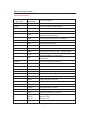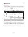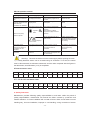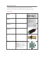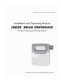
1
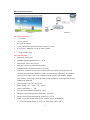
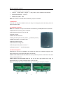
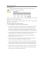
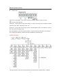
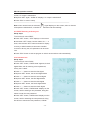
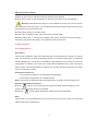
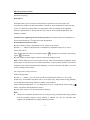
Operating manual of Controller SR1128
For split pressurized solar hot water system
SR1128 operation manual
Content
1. Safety information .................................................................................................... 3
1.1 Installation and commissioning ............................................................................... 3
1.2 About this manual ................................................................................................... 3
1.3 Liability waiver ........................................................................................................ 3
1.4 Important remark .................................................................................................... 4
1.5 Description of symbols ........................................................................................... 4
2. Overview .................................................................................................................. 4
2.1 Introduction of controller ......................................................................................... 4
2.2 Scope of delivery .................................................................................................... 5
2.3 Technical data ........................................................................................................ 5
3. Installation ................................................................................................................ 6
3.1 Installing controller .................................................................................................. 6
3.2 Wire arrangement ................................................................................................... 6
3.3 Wire connection...................................................................................................... 7
3.4 Menu structure ....................................................................................................... 8
3.5 Menu description .................................................................................................... 9
3.6 System description ............................................................................................... 10
1 collector array- 1tank -1 circuit pump-back-up heater ............................................... 10
4. Function operation and parameter setup (user grade) ............................................. 11
4.1 Set time/week ........................................................................................................ 11
4.2 tHET Timing Heating ............................................................................................. 11
5. Function operation and parameter setup (engineer grade) ...................................... 15
5.1 Access main menu ............................................................................................... 15
5.2 DT Temperature difference ................................................................................... 15
5.3 TEMP Temperature............................................................................................... 16
5.3.1 EMOF Collector maximum switch-off temperature (for collector emergency close
function) ..................................................................................................................... 17
5.3.2 EMON Collector maximum switch-on temperature (for collector emergency close
function) ..................................................................................................................... 18
5.3.3 CMX Maximum limited collector temperature (collector cooling function) ........... 18
5.3.4 CMN low temperature protection of collector...................................................... 19
5.3.5 CFR frost protection of collector ......................................................................... 20
5.3.6 REC Storage re-cooling function ........................................................................ 20
5.3.7 Maximum temperature of tank 1 ........................................................................ 21
5.4 PUMP circuit pump speed adjust set .................................................................... 22
5.4.1 DTS Standard temperature difference for circulation pump 1 (speed adjusting) . 22
5.4.2 RIS Gain for circulation pump 1 (speed adjusting) ............................................. 23
~1~
SR1128 operation manual
5.5 OHQM Thermal energy measuring ....................................................................... 23
5.5.1 FMAX Flow rate ................................................................................................. 24
5.5.2 MEDT Type of heat transfer liquid ...................................................................... 25
5.5.3 MED% Concentration of heat transfer liquid ...................................................... 25
5.6 INTV Pump interval function ................................................................................. 25
5.6.1 ISTAR Turn-on time set for pump interval running function ................................. 26
5.6.2 IEND Turn-off time set for pump interval running function .................................. 26
5.6.3 ISTP Pump interval time .................................................................................... 26
5.6.4 IRUN Pump running time ................................................................................... 27
5.7 FUN Auxiliary function .......................................................................................... 27
5.7.1 DVWG Anti legionnaires' function ...................................................................... 27
5.8 OSDC SD card data save function ........................................................................ 28
5.8.1 OSDC Card function switch-on and off............................................................... 28
5.8.2 LOGI Data save intervals ................................................................................... 28
5. 9 UNIT Display unit oC and ̧ switches .................................................................. 29
5.10 HND Manual control ........................................................................................... 29
5.11 REST Recovery to factory set ............................................................................. 30
5.12 Password set ...................................................................................................... 30
6. Button function ....................................................................................................... 31
6.1 Holiday function .................................................................................................... 31
6.2 Manual heating ..................................................................................................... 32
6.3 Temperature query function .................................................................................. 32
7 Protection function................................................................................................... 33
7.1. Memory protection ............................................................................................... 33
7.2 Screen protection ................................................................................................. 33
7.3 pump idling protection .......................................................................................... 33
8. Trouble shooting ..................................................................................................... 34
8.1 Trouble protection ................................................................................................. 34
8.2 Trouble checking .................................................................................................. 34
9. Quality Guarantee .................................................................................................. 35
10. Accessories .......................................................................................................... 36
~2~
SR1128 operation manual
1. Safety information
1.1 Installation and commissioning
x
When laying cables, please ensure that no damage occurs to any of the constructional
fire safety measures presented in the building.
x
The controller must not be installed in rooms where easily inflammable gas mixtures are
present or may occur.
x
The permissible environmental conditions can’t be exceeded at the site of installation.
x
Before connecting the device, make sure that the energy supply matches the
specifications that controller requires.
x
All devices connected to the controller must conform to the technical specifications of
the controller.
x
All operations on an open regulator are only to be conducted cleared from the power
supply. All safety regulations for working on the power supply are valid.
x
Connecting and /or all operations that require opening the regulator (e.g. changing the
fuse) are only conducted by specialists.
1.2 About this manual
This manual describes the installation, function and operation of a solar thermal controller.
When installing the remaining components e.g. the solar collectors, pump assemblies and
the storage unit, it should be sure to observe the appropriate installation instructions
provided by each manufacturer. Only trained professional personnel may perform
installation, electrical connection, commissioning and maintenance of the device. The
professional personnel must be familiar with this manual and follow the instructions
contained herein.
1.3 Liability waiver
The manufacturer cannot monitor the compliance with these instructions or the
circumstances and methods used for installation, operation, utilization and maintenance of
this controller. Improper installation can cause damages to material and person. This is the
reason why we do not take over responsibility and liability for losses, damages or cost that
might arise due to improper installation, operation or wrong utilization and maintenance or
that occurs in some connection with the aforementioned. Moreover we do not take over
liability for patent infringements or infringements – occurring in connection with the use of
this controller- on third parties rights. The manufacturer preserves the right to put changes
to product, technical date or installation and operation instructions without prior notice. As
soon as it becomes evident that safe operation is no longer possible (e.g. visible damage).
~3~
SR1128 operation manual
Please immediate take the device out of operation. Note: ensure that the device cannot be
accidentally placed into operation.
1.4 Important remark
We have carefully checked the text and pictures of this manual and provided the best of our
knowledge and ideas, however inevitable errors maybe exist. Please note that we cannot
guarantee that this manual is given in the integrity of image and text, they are just some
examples, and they apply only to our own system. Incorrect, incomplete and erroneous
information and the resulting damage we do not take responsibility.
1.5 Description of symbols
Safety instruction:
The safety instructions in the manual are marked with a warning triangle. They
indicate measures, which can lead to personal injury and safety risks.
Operation steps: small triangle “►”is used to indicate operation step.
Notes: Contains important information about operation or function.
2. Overview
2.1 Introduction of controller
x
LCD display
x
4 sensor inputs
x
1 relay output
x
1 PWM output for speed control of pump
x
Data saved on SD card ( Picture 1, 2, 3)
x
RS485 remote control( Picture 4)
x
Timing and temperature set point control function
x
Energy saved on/off operation model
Picture 1
Picture 2
~4~
SR1128 operation manual
Picture 3
Picture 4
2.2 Scope of delivery
x
1 x controller
x
1 x user manual
x
2 x screw and dowel
x
1 x PT1000 sensor (φ6*50mm,length of cable 1.5 meter˅
x
2 x NTC10K˄φ6*50mm, length of cable 3 meter˅
x
1 x bag of strain relief
2.3 Technical data
x
Material of cases: ABS
x
Available ambient temperature: 0 ... 40 oC
x
Dimensions: 188 x 138 x 43 mm
x
Mounting: on wall or in the electrical cases
x
Operation button: 6 operation buttons on panel
x
Functions: controller used in solar hot water system and solar heating system, has
functions like temperature difference control, thermal energy measuring, accumulated
running time of solar circuit pump, collector interval function, thermostator, storage
layer heated , priority logic, back-up heating, heat transferring, Anti-Legionella function,
PWM pump speed etc.
x
Communication port: SD card groove.
x
Power supply: 100 ... 240V ~, 50 ... 60 H z
x
Power consumption :˘ 1W
x
Accuracy of temperature measuring : ±2 oC
x
Range of collector temperature measuring: -10- 200oC
x
Range of tank or pipe temperature measuring: 0-110oC
x
Inputs: 1 x Pt1000 sensor (≤500oC) for collector (silicon cable≤280oC),
3
x NTC10K, B3950 sensor (≤ 135oC) for tank, (PVC cable ≤105oC),
~5~
SR1128 operation manual
1 x RS485 remote control connection
x
Outputs˖1 PWM output˄≤200W˅; 1 relay output ( each available power≤300W˅
x
Ambient temperature˖-10-50 oC
x
Water proof grade˖IP40
Note: SD card isn’t included within the delivery scope of controller.
3. Installation
Controller can only be installed indoors, far away from dangerous place and away from the
electromagnetic field.
3.1 Installing controller
Note: the controller can only be mounted in an area having an adequate level of protection.
► Determine the mounting site of controller.
► Drill the upper fixing hole on the wall.
► Fasten a screw.
► Move the terminal cover
► Hang the base plate on the position ķ( showed in picture)
► Mark the position of 2 bottom holes ĸ
► Remove the base plate
► Drill the bottom fixing hole
► Re-hang the base plate on screw ķ
► Fasted screw on ĸ and fix base plate.
3.2 Wire arrangement
Depending on the type of installation, the cables may enter the controller through the rear
hole of the case A or the lower side hole of the case B.
Cable comes from the rear hole A: Remove the plastic flaps from the rear side of the case
using an appropriate tool.
Cable comes from the below hole B: Cut the left and right plastic flaps using an
appropriate tool (e.g. knife) and break them out of the case.
Notes: the flexible wire must be fastened on the case using the clamps C provided.
~6~
SR1128 operation manual
3.3 Wire connection
Before opening the terminal, please be sure to switch-off the power and pay
attention to the local electricity supply rules.
Input Ports:
Inputs T1˖For PT1000 temperature sensor, used for measuring the temperature of collector
and measuring the produced thermal energy.
Inputs T2 ̚ T4 ˖ for NTC10K, B=3950 temperature sensor, used for measuring the
temperature of storage or pipe.
VBus (485): for RS485 remote control connection.
z
Advice regarding the installation of temperature sensors
¾
Only original factory enclosed Pt1000 temperature sensors are approved for use with
the collector, it is equipped with 1.5meter silicon cable and suitable for all weather
conditions, the temperature sensor and cable are temperature resistant up to 280 oC,
not necessary to distinguish the positive and negative polarity of the sensor connection.
¾
Only original factory enclosed NTC10K, B=3950 temperature sensors are approved for
use with tank and pipe, it is equipped with 1.5meter PVC cable, and they are
temperature resistant up to 105oC, not necessary to distinguish the positive and
negative polarity of the sensor connection.
¾
All sensor cables carry low voltage, and to avoid inductive effects, must not be laid
close to 230 volt or 400-volt cables (minimum separation of 100mm)
¾
If external inductive effects are existed, e.g. from heavy current cables, overhead train
cables, transformer substations, radio and television devices, amateur radio stations,
microwave devices etc, then the cables to the sensors must be adequately shielded.
¾
Sensor cables may be extended to a maximum length of ca. 100 meter, when cable’s
2
length is up to 50m, and then 0.75mm cable should be used. When cable’s length is
2
up to 100m, and then 1.5mm cable should be used.
~7~
SR1128 operation manual
z
Output ports
Input Ports: Input ports L, N is power connection terminal, please connect correctly.
is Ground line terminal.
Output P1˖Semiconductor relay (SCR relay), for solar circuit pump, also suitable for RPM
(speed) control; Max. Switching current: 1A.
Output H1˖for by-pass circuit pump or valve, electromagnetic relay, max. switching current
3.5A, R1 ports are always open
Note: Depending on the solar system selection, pump and sensors should be connected to
the controller are different, all wires should be installed in protection pipe.
3.4 Menu structure
Submenu:
Through submenu, user can set the parameter as desired value, please check it carefully.
~8~
SR1128 operation manual
3.5 Menu description
Code
˄Main menu˅
Code
(Submenu)
Menu Description
DT
For set the operation temperature difference
TEMP
For set correlative temperatures
EMOF
The maximum switch-off temperature of collector
EMON
The maximum switch-on temperature of collector
CMX
The maximum temperature of collector
(Collector cooling function)
CMN
Low temperature protection of collector
CFR
Frost protection of collector
REC
Tank recooling function
SMX1
Maximum temperature of tank1
PUMP
For set the speed parameters of circuit pump
nMIN
DTS
RIS
OHQM
Speed adjust of circuit pump (RPM control)
Standard temperature difference of pump
(for speed adjust of circuit pump )
Increase scale of pump (for speed adjust of
circuit pump )
For thermal energy measuring
FMAX
Flow rate
MEDT
Type of heat transfer liquid
MED%
ISTAR
Concentration of heat transfer liquid
For timing function
Switch-on time of timing function
IEND
Switch-off time of timing function
IRUN
Pump interval run-on time
ISTP
Pump interval run-off time
INTV
FUN
Auxiliary functions
DVWG
OSDC
Anti legionnaires' function
SD card function
LOGI
Data save interval ( in minute)
NOCRD
FAT16
FAT32
No card in groove
Memory < 2G
Memory > 2G
RTIME
left time available for saving data ( in day)
~9~
SR1128 operation manual
FSYS
LOGG
Error on system files
Possible to log
UNIT
Celsius and Fahrenheit temperature switch
HDN
Manual controlling
REST
Recovery to factory set
PASS
Password set
3.6 System description
Note: storage temperature sensor T3 is optional sensor, if this sensor is not installed on the
upper part of the storage, controller will adopt the temperature signal from sensor T2
installed on the bottom part of storage to control back-up heater or circuit pump.
1 collector array- 1tank -1 circuit pump-back-up heater
System description:
Controller compares the temperature between collector T1 and storage T2 ( bottom part), if
the temperature difference ˄DT˅ rises up to the preset switch-on (ΔT1)or is over it, circuit
pump P1 is triggered , and then storage is heated until DT drops to the switch-off DT or
when the storage temperature T3 rises up to its preset maximum temperature. Then circuit
pump P1 is ceased.
Back-up heating: ( see details at tHET timing heating menu)
With the preset heating time section, if tank temperature (T3) drops to the switch-on
temperature of heating, then back-up heat resource H1 is triggered automatically, when
tank temperature T3 rises up to the preset switch-off temperature, then output H1 is ceased.
T1: Temperature sensor on collector
T2: Temperature sensor on the bottom
part of tank
T3: Temperature sensor on the top part
of tank (optional)
T4˖Sensor for thermal energy
measuring function, installed on the flow
pipe to collector(not included within
delivery scope)
P1: Solar circuit pump
H1˖Back-up heater
~10~
SR1128 operation manual
4. Function operation and parameter setup (user grade)
4.1 Set time/week
►Press “SET” button, “TIME” displays on the screen,
►Repress “SET” button, hour selection area “00” blinks on the display screen.
►Press “+” “-” button to set hour of clock
►Press “SET” button again; minute area“00”blinks
►Press “+” “-” button to set minute of clock.
►Press “SET” again, week area “MO” blinks
►Press “+” “-” button to set week.
►Press “SET” again, “DAY/MONTH/YEAR” area “Year” blinks
►Press “+” “-” button to set year.
Code
Meaning
►Press “SET” again, “Month” blinks
MO
Monday
►Press “+” “-” button to set month.
TU
Tuesday
►Press “SET” again, ĀDAY” blinks
WE
Wednesday
TH
Thursday
FR
Friday
SA
Saturday
SU
Sunday
►Press “+” “-” button to set day.
►Press “ESC” button to exit set program, or wait for 20 seconds to
exit program automatically. The set parameter values of time and
week are saved automatically,
4.2 tHET Timing Heating
Description:
Electrical heater, gas boiler or oil boiler can be integrated into solar system used as back-up
of system, and they can be triggered automatically at preset schedule by preset
temperature. Within a preset schedule, when the temperature (T3) of top part of tank
drops below the preset switching-on temperature of this function, back-up heating H1 starts
to work, when T3 rises up to the preset turning off temperature, back-up heating is stopped.
Within 24 hours, three time sections can be set with this controller.
Factory set:
The first schedule: back-up heating function starts at 4:00 and ends at 5:00 am. Within this
time section, default switch-on temperature is 40oC; default switch-off temperature is 45oC.
The second schedule: starts at 10:00 and ends also at 10:00 am, it means no back-up
heating in this time.
The third schedule: back-up heating function starts at 17:00 and ends at 22:00 pm. Within
this time section, default switch-on temperature is 50oC; default switch-off temperature is
~11~
SR1128 operation manual
55oC.
The switch-on temperature adjustable range: 10 oC ~ (OFF-2 oC)
The switch-off temperature adjustable range: (ON+2 oC) ~ 80 oC
If you want to shut off one timing heating, then you can set the turning on time and turning
off time with a same value (for example, the second time section no this function, then you
can set turning on/off time is 10:00 ~ 10:00)
When time is outside of the preset schedule, back-up heating doesn’t work automatically
even when the tank temperature drops to the switch –on temperature of heating.
Note:
x
When there is no sensor installed in the top part of tank (no T3 sensor), controller will
take the signal of T2 (sensor in bottom of tank) automatically to control this function.
x
The time in this controller is 24 hours model, when you set schedule, the switch-off
time of heating should be larger than switch-on time. For example: if you set the
switch-on time of heating is at 17:00, but switch-off time of heating is 6:00, then this
setting doesn’t take effect, that means within this time section, heating function doesn’t
work.
The correct set is like flowing: it should be divided into two time sections, one
time section is from 17:00 to 23:59, the other time section is from 00:00 to 06:00.
Setup steps: under standby,
► Press “SET” button, “tHET” displays on the screen.
► Repress “SET” button to access “tHET” program
menu.
► Repress “SET” button again, to set parameters of
“tHET”, “tH 1o 04:00” displays on the screen, “04” of
hour time blinks on screen, the switch-on time and
temperature for the first schedule of heating function
can be set.
►Press “+” “-” button to adjust hour of time.
►Repress “SET” button again, “00” of minute time
blinks on screen.
►Press “”“”button to adjust minute of time.
►Repress “SET” button, temperature “40ć” blinks on
screen.
►Press “”“”button, to set the switch-on temperature
of heating.
►Then, press “ESC” to exit this submenu.
~12~
SR1128 operation manual
►Press “+” button, “tH 1F 05:00” displays on the screen, to access the submenu of the
switch-off time and temperature for the first schedule of heating function.
► Press “SET” button again, “05” of hour time blinks on screen.
►Press “+” “-” button to adjust hour of time.
►Repress “SET” button again, “00” of minute time blinks on screen.
►Press “”“”button to adjust minute of time.
►Repress “SET” button, temperature “45ć” blinks on screen.
►Press “”“”button, to set the switch-off temperature of heating.
►Then, press “ESC” to exit this submenu, or wait for 20 seconds to exit automatically, the
parameter valves are saved automatically.
--------------------------------------------------------------------------------------------------------------------------
►Press “+” button, “tH 2o 10:00” displays on the screen, to access the submenu of the
switch-on time and temperature for the second
schedule of heating function.
► Press “SET” button again, “10” of hour time blinks on
screen.
►Press “+” “-” button to adjust hour of time.
►Repress “SET” button again, “00” of minute time blinks on screen.
►Press “”“”button to adjust minute of time.
►Repress “SET” button, temperature “50ć” blinks on screen.
►Press “”“”button, to set the switch-on temperature of heating.
►Then, press “ESC” to exit this submenu.
►Press “+” button, “tH 2F 10:00” displays on the screen, to access the submenu of the
switch-off time and temperature for the second
schedule of heating function.
► Press “SET” button again, “10” of hour time blinks
on screen.
►Press “+” “-” button to adjust hour of time.
►Repress “SET” button again, “00” of minute time
blinks on screen.
►Press “”“”button to adjust minute of time.
►Repress “SET” button, temperature “55ć” blinks on screen.
►Press “”“”button, to set the switch-off temperature of heating.
►Then, press “ESC” to exit this submenu, or wait for 20 seconds to exit automatically, the
parameter valves are saved automatically.
~13~
SR1128 operation manual
--------------------------------------------------------------------------------------------------------------------------
►Press “+” button, “tH 3o 17:00” displays on the screen, to access the submenu of the
switch-on time and temperature for the third schedule of heating function.
► Press “SET” button again, “17” of hour time blinks
on screen.
►Press “+” “-” button to adjust hour of time.
►Repress “SET” button again, “00” of minute time
blinks on screen.
►Press “”“”button to adjust minute of time.
►Repress “SET” button, temperature “50ć” blinks on screen.
►Press “”“”button, to set the switch-on temperature of heating.
►Then, press “ESC” to exit this submenu.
►Press “+” button, “tH 3F 22:00” displays on the
screen, to access the submenu of the switch-off time
and temperature for the third schedule of heating
function.
► Press “SET” button again, “22” of hour time blinks on screen.
►Press “+” “-” button to adjust hour of time.
►Repress “SET” button again, “00” of minute time blinks on screen.
►Press “”“”button to adjust minute of time.
►Repress “SET” button, temperature “55ć” blinks on screen.
►Press “”“”button, to set the switch-off temperature of heating.
►Then, press “ESC” to exit this submenu, or wait for 20 seconds to exit automatically, the
parameter valves are saved automatically.
-------------------------------------------------------------------------------------------------------------------------Note: when no gas or oil boiler is connected to solar system, electrical heater can be
installed as back-up device, when electrical heater is in operation status, signal
on screen, and LED light is on.
Application sample:
1
2
3
~14~
blinks
SR1128 operation manual
If customer uses electrical heater as back-up, please according to the power of electrical
heater to equip corresponding safety devices like contactor and breaker with this controller,
we strongly recommend equipping with SR802 device with this controller, (SR802 detailed
technical data see paragraph spare parts)
5. Function operation and parameter setup (engineer grade)
5.1 Access main menu
Under standby, doing like following to access main menu.
►Press “SET” button, then press “+” button 3 times and wait for “PWD 0000” appears on
the screen, then repress “SET” button, the left first
digital blinks, ask for entering password, factory
default set password is “0000”
►Press “+” “-” button to enter first digital of password.
►Repress “SET” button, the second digital blinks
►Repress “+” “-” button, to enter second digital of password.
►Repeat press “SET” button, the third digital blinks
►Repress “+” “-” button, to enter third digital of password.
►Repeat press “SET” button, the forth digital blinks
►Repress “+” “-” button, to enter forth digital of password.
►Repress “SET” button, to access the main menu.
►Press “+” “-” button, select any menu you wanted.
►Press “ESC” button, you can exit main menu.
Note: default factory set password is “0000”, if you don’t set new password, just press “SET”
four times, then you can access main menu interface
5.2 DT Temperature difference
Description:
Solar circuit pump P1 is triggered by the temperature difference function, so long as the
temperature difference between collector and storage reaches the switch-on DT, solar circuit
pump is triggered.
For example: the switch-on DT is 8oC, switch-off DT is 4oC, if the temperature on the bottom
part of storage is 20oC, then just when collector temperature rises up to 28 oC, pump is
triggered, and when collector temperature drops to 24 oC, pump is ceased.
o
o
Note: the switch-on/off DT of 8 C and 4 C are standard system setting according to many
~15~
SR1128 operation manual
years’ experience, only in special application cases it needs to be changed, (e.g. far
distance heat transferring), normally we recommend using default set. Switch-on and
switch-off DT are alternating set. To avoid mistake the minimum difference between two
temperature differences (ΔTon –ΔToff) is set as 2 oC.
Setup temperature difference:
Under standby, following steps descript in paragraph 6.1 to access main menu DT
►Press “SET” button, to access settings program of main menu DT, “DT 1o 08 oC” displays
on
screen,
“08
o
C”
blinks,
the
first
switch-on
temperature difference can be set.
►Press “+” “-” button, to adjust the value of switch-on
DT, adjustable range (OFF+2 oC ˅ ̚ 20 oC, factory
setting is 8 oC
►Press “ESC” button to exit this setting, parameter is saved automatically.
►Press “+” button, “DT 1F 04 oC” displays on screen,
the first switch-off temperature difference can be set.
►Press “SET” button, “04 oC” blinks.
►Press
“+” “-” button to adjust the value of switch-off
DT, adjustable range 0 oC̚˄ON-2 oC˅ˈfactory set is 4
o
C.
►Press “ESC” to exit menu, or wait for 20 seconds to exit automatically, the setup
parameters are saved automatically.
5.3 TEMP Temperature
For solar system, the factory set parameters are for the best operation condition, which is
fully integrated into the entire solar system. But these parameters can also be set
individually to cater the special requirements, please carefully observe the operation data of
system components after setting.
Note: Parameters that can be set rely on the system design, not all the parameters can be
Following submenu can be access though TEMP main menu.
~16~
SR1128 operation manual
Tem.
Code
Function of temperature
Adjustable range
Factory
set
EMOF
Collector maximum switch-off temperature
(ON+3 oC)~ 200 oC
130 oC
o
o
EMON
Collector maximum switch-on temperature
80 C ~ (OF-3 C)
CMX
Maximum limited collector temperature
(collector cooling function)
70 C ~190 C
CMN
Low temperature protection of collector
CFR
Frost protection of collector
REC
Tank re-cooling function
SMX1
Maximum temperature of tank 1
o
o
o
o
0 C~90 C
o
o
-10 C~10 C
Function
exit tem.
5.3.1
o
120 C
o
110 C
5.3.2
o
107 C
o
2 C~95 C
5.3.3
---
5.3.4
---
5.3.5
OFF
o
Paragraph
o
60 C
5.3.6
o
58 C
5.3.7
5.3.1 EMOF Collector maximum switch-off temperature (for collector emergency close
function)
Function description:
When collector temperature rises up to this maximum switch-off limited temperature (EM),
collector emergency function is activated, solar circulation pump is stopped in order to avoid
the damage of system’s other components caused by high temperature. The adjustable
range of EMOF temperature is ˄ON+3 oC˅̚200 oC, factory set is 130 oC. If the temperature
of collector rises up to EMOF limited temperature, solar circuit pump is ceased, but when
collector temperature drops to the collector maximum switch-on temperature EMON˄factory
set is
120oC˅, solar circuit pump will be reset, and collector emergency close function is
deactivated.
Setup steps:
To access main menu TEMP, then select submenu EMOF, “EMOF 130oC” displays on the
screen
►Press “SET” button, parameter “130 oC” blinks.
►Press “+” “-” button, to adjust this maximum
switch-off temperature, adjust range (ON+3 oC˅̚200
o
C, factory set is 130 oC
►Repress “SET” button to activate and deactivate this function, if deactivate the function,
“EMOF - - -” displays on the screen.
► Press “ESC” button to exit menu or wait for 20 seconds to exit automatically, set
parameters are saved automatically.
~17~
SR1128 operation manual
5.3.2 EMON Collector maximum switch-on temperature (for collector emergency
close function)
Setup steps:
To access main menu TEMP, then select submenu
EMON, “EMO 120oC” displays on screen
o
►Press “SET” button, parameter “120 C” blinks.
►Press “+” “-” button, to adjust this maximum
switch-on temperature, adjust range 80 oC ~ (OF-3 oC),
factory set is 120 oC
►Repress “SET” button to activate and deactivate this function, if deactivate the function,
“EMON - - -” displays on screen.
► Press “ESC” button to exit menu or wait for 20 seconds to exit automatically, set
parameters are saved automatically.
When these two signals of EM blink on the screen, it indicates collector
emergency close function is activated, and at this moment temperature of
tanks reaches to its maximum limited temperature
When only this signal of EM blinks on the screen, it indicates collector emergency
close function is also activated, but temperature of tank doesn’t reach to its
maximum limited temperature
5.3.3 CMX Maximum limited collector temperature (collector cooling function)
Function description:
If hot water in tank isn’t used for long time, then the capacity that solar system absorbs solar
irradiation reduces, when tank temperature rises to its preset maximal temperature, solar
circuit pump is ceased compulsively even the temperature difference is satisfied. then when
more solar irradiation shines in, as a result collector temperature will rise continuously,
temperature of collector maybe rise up to the evaporated temperature of heat fluid, this
phenomenon names collector
- overheat, it should be avoided. Through set the Maximum
limited collector temperature˄collector cooling function˅ it can delay the vaporization of the
heat transfer fluid. Shortly before reaching the maximum temperature of the collector, the
solar pump starts working to cool down the heat transfer fluid using the heat losses
occurring in pipelines and storage cylinder.
When collector temperature rises up to its maximal temperature, solar pump will be
triggered again even at the case that tank temperature is already to its maximal temperature.
And solar pump works until the temperature of collector drops because of this reversed
~18~
SR1128 operation manual
circulation or when tank temperature rises its emergency temperature (95 oC).
When
displays, and
blinks on the screen, it indicates that tank emergency
temperature reaches, tank temperature is ≥95ć
Setup steps:
To access main menu TEMP, then select submenu CMX, “CMX 110 oC” displays on screen
o
►Press “SET” button, “110 C” blinks.
►Press “+” “-” button to adjust collector limited
o
maximum temperature , adjust range ˄70
:
C̚190 oC˅,
o
Factory set is 110 C
►Press “SET” button to activate and deactivate this
function, if deactivate the function, “CMX - - -” displays on screen.
► Press “ESC” button to exit menu or wait for 20 seconds to exit automatically, set
parameters are saved automatically.
CMX signal displays on screen, it indicates that collector cooling function is activated.
5.3.4 CMN low temperature protection of collector
Description:
When the actual temperature of collector is below the preset CMN temperature, solar circuit
pump is ceased, even when the temperature difference between collector and storage
exceeds switch-on temperature difference, solar pump doesn’t work yet. When the
temperature of collector is 3 oC higher than the preset CMN temperature, solar circuit pump
is standby to work, controller exits this program.
Setup steps:
To access main menu TEMP, then select submenu CMX, “CMN - - -” displays on screen,
default set is OFF.
►Press “SET” button, default off signal “- - -” blinks on
screen.
►Repress “SET” button to activate and deactivate this
function.
►Press
“+” “-” button to adjust the low protection temperature of collector CMN, adjustable
o
range (00 C ̚90 oC ), after activate the function, factory set is 10 oC
► Press “ESC” button to exit the menu or wait for 20 seconds to exit automatically,
parameters are saved automatically.
~19~
SR1128 operation manual
CMN signal displays on screen, it indicates that this function is activated.
5.3.5 CFR frost protection of collector
Description:
In winter when the temperature of collector is below the preset frost protection temperature
(factory set is 4 oC), solar circuit pump is triggered to transfer hot water from tank to collector
and to heat collector by this reversed circuit. And when tank temperature (T2) drops to 6oC,
electrical heater is triggered automatically and it keeps running until tank temperature T2
raises up to 21 oC or it is stopped when program of CFR is exited. When collector
temperature rises up to 7 oC, solar circuit pump is ceased, program of CFR exits
automatically.
This function is used in system, which uses water as heat transfer liquid, to avoid the
freezing of solar heat transfer fluid.
Setup steps:
To access main menu TEMP, then select submenu CFR, “CFR ----” displays on screen,
default set is off.
►Press “SET” button, default off “- - -” blinks.
►Repress “SET” button to activate or deactivate this
function
►Press “+” “-” button to adjust the temperature of frost
protection function, adjustable range is ˄-10 oC̚10 oC˅ˈ after function activated, default
o
set is 4 C
► Press “ESC” button to exit the menu or wait for 20 seconds to exit automatically,
parameters are saved automatically.
CFR signal displays on screen, it indicates that this function is activated.
Note: this function is only available in special solar system which using no-anti-freezing
liquid; this kind of system is only suitable in area where the ambient temperature is near to
0oC only for a few days. If safety requirement is very high, then anti-freezing is necessary,
we suggest using suitable anti-freezing liquid to avoid frost problem.
5.3.6 REC Storage re-cooling function
Description:
If storage temperature rises up to its maximum temperature, and at the same time, collector
temperature is 5oC lower than storage temperature, then solar pump can be triggered,
~20~
SR1128 operation manual
through this reversed circulation, storage temperature is reduced by heat loss occurs in
collector, solar pump keeps in working until storage temperature drops below its maximum
temperature.
Setup steps:
To access main menu TEMP, then select submenu REC, “REC OFF” displays on screen,
default set is off.
►Press “SET” button, parameter “OFF” blinks on
screen
►Repress “SET” button to activate or deactivate this
function; after function activated, factory set is “REC
ON”
► Press “ESC” button to exit the menu or wait for 20 seconds to exit automatically,
parameters are saved automatically.
REC signal displays on screen, it indicates that this function is activated.
5.3.7 Maximum temperature of tank 1
Description:
When the DT between collector T1 and tank 1 caters the switch-on DT of circulation, solar
pump is triggered, but in order to avoid the high temperature inside tank, controller will
check whether the temperature (T3) of the top part of tank is higher than the maximum
temperature of tank, when T3 is higher than the preset maximum tank temperature SMX,
solar pump is ceased even at the case that DT caters condition. When tank temperature
drops and is 2oC below the SMX temperature, solar pump restarts when DT caters
condition.
Setup steps:
To access main menu TEMP, then select submenu SMX1, “SMX1 60 oC” displays on
screen.
►Press “SET” button, parameter “60 oC” blinks
►Press “+” “-” button to adjust the value of maximum
o
o
temperature of tank1, adjustable range is˄2 C̚95 C˅,
default set is 60 oC
►Repress “SET” button to activate and deactivate this function, if function deactivated,
“SMX1 - - -” displays on the screen.
► Press “ESC” button to exit the menu or wait for 20 seconds to exit automatically,
parameters are saved automatically.
~21~
SR1128 operation manual
SMX signal displays on screen, it indicates that this function is in activated.
5.4 PUMP circuit pump speed adjust set
Description:
P1 output can be configured to function either as RPM controlled output or simple switch
output.
When nMIN is set as 30-90%, P1 output used as RPM output.
When nMIN is set as 100%, it means P1 output used as switch output.
Normal switch output: circuit pump speed control˄RPM˅is deactivated, pump is operated
with a fixed speed, and flow rate is not changed.
RPM control output: (speed control is activated), the
control system attempts to maintain a constant
temperature difference between collector and tank.
The pump performance is continuously adjusted,
based on the temperature difference flow rate of pump is increased or reduced.
Setup steps:
To access main menu PUMP, “PUMP” displays on the screen, press “SET” to access the
menu, then “nMIN 100” displays on screen.
►Press “SET” button, parameter” 100” blinks on the
screen.
►Press “+” “-” button, to adjust pump speed.
adjustable range: (30̚100%˅, factory set is 100%.
►Press “ESC” button to exit the menu or wait for 20 seconds to exit automatically,
parameters are saved automatically.
5.4.1 DTS Standard temperature difference for circulation pump 1 (speed adjusting)
Description:
The preset default minimum pump speed in this controller is 30%. When the switch-on
temperature difference (ƸTON) reaches, solar pump is triggered, and then within 10
seconds, pump speed increases to its minimum speed (30%). Thereafter, controller checks
temperature continuously, when a standard temperature difference (DTS) reaches, the
speed of pump increases one grade (10%), temperature difference RIS increases every 1oC,
speed of pump increases 10% until it reaches to its maximum speed 100%. Through setting
the temperature difference increase rate (RIS) can achieve the controlling of pump speed. If
temperature difference drops to the switch-off temperature difference (ƸT OFF), circuit
pump is ceased.
~22~
SR1128 operation manual
Setup steps:
To access PUMP, then select submenu DTS “DTS 08 oC” displays on screen.
►Press “SET” button, parameter “08oC” blinks on the
screen
►Press “+” “-” button, to adjust the standard DTS,
adjustable range ˄2 oC̚30 oC˅, factory set is 08oC
►Press “ESC” button to exit the menu or wait for 20
seconds to exit automatically, parameters are saved automatically.
5.4.2 RIS Gain for circulation pump 1 (speed adjusting)
Setup steps:
To access menu PUMP, then select submenu RIS,
“RIS 01 oC” displays on screen.
o
►Press “SET” button, parameter “01 C” blinks on the
screen
►Press “+” “-” button, to adjust standard RIS,
adjustable range ˄1 oC̚20 oC˅, factory set is 1oC
►Press “ESC” button to exit the menu or wait for 20 seconds to exit automatically,
parameters are saved automatically.
5.5 OHQM Thermal energy measuring
Description:
Controller has function for measuring the thermal energy; it can measure the energy which
is transferred from collector to tank. For the sake of measuring, the temperature on flow and
return pipe should be checked, and an extra flow meter should be installed on the
circulation pipe, it is used for measuring the flow rate.
The thermal energy transferred by solar system is calculated with measured parameters
flow rate and temperature T0 (installed on the return pipe). Thermal energy got in the
current day displays in DkWh, accumulative thermal energy displays in kWh or MWh. The
amount of 2 values is the total energy output.
Note: when T0 input is used, (for example, used in east/west collector), OHQM thermal
energy measuring function will be deactivated. Factory set of OHQM is off.
Setup steps:
To select menu OHQM, “OHQM” displays on the
screen,
►Press “SET” button, parameter “OHQM OFF”
appears on the screen
~23~
SR1128 operation manual
►Press “SET” button, parameter “OFF” blinks on the screen
►Repress “SET” button to activate this function, then
“OHQM ON” appears on the screen
► Press “ESC” button to exit the menu or wait for 20
seconds to exit automatically, parameters are saved
automatically.
Thermal energy got in current day, accumulative thermal energy and operation time of pump
can be reset, doing like following.
Operation steps: under standby status,
►Press “+” “-” button, select the thermal energy of current day, “DKWH XX” “SET” displays
on the screen.
►Press “SET” button for 3 seconds, buzzer makes 3 times “du-----“, the daily thermal
energy is cleared, and daily thermal energy is reset to “00”.
►Press “+” “-” button, select to check accumulative thermal energy, “KWH XX” or “MWH
XX”
“SET” displays on the screen.
►Press “SET” button for 3 seconds, buzzer makes 3 times “du-----”, the sum thermal
energy is cleared, and accumulative thermal energy is reset to “00”.
►Press“+” “-” button, select the operation time of pump, “hP XX” “SET “displays on the
screen.
►Press “SET” button for 3 seconds, buzzer makes 3 times “du-----”, the operation time of
pump is cleared, and it is reset to “00”.
Note˖
˖Only when the thermal energy measuring function is activated, operation time of
circulation pump function just can be triggered.
5.5.1 FMAX Flow rate
FAMX: Flow rate L/min. adjustable range: (0.1̚20) L/min, increase rate 0.1L per button
press, factory set is 2.0L/min
Setup steps:
To select submenu FMAX, “FMAX 2.0” displays on the screen.
►Press “SET” button, parameter “2.0” blinks on the
screen
►Press “+” “-” button to adjust parameter of flow rate.
adjustable range˄0.1̚20˅
► Press “ESC” button to exit the menu or wait for 20
seconds to exit automatically, parameters are saved automatically.
~24~
SR1128 operation manual
5.5.2 MEDT Type of heat transfer liquid
MEDT: type of heat transfer liquid, adjustable range (00̚03)ˈ factory set ˖01
Type of heat transfer liquid:
00˖Water
01˖Propylene glycol
02˖Glycol
03˖Tyfocor LS/G-LS
Setup steps:
To select submenu MEDT, “MEDT 01” displays on screen.
►Press “SET” button, parameter “01” blinks on the screen
►Press “+” “-” button, to adjust type of heat transfer liquid, adjustable range (00̚03˅
► Press “ESC” button to exit the menu or wait for 20 seconds to exit automatically,
parameters are saved automatically.
5.5.3 MED% Concentration of heat transfer liquid
MED% Concentration of heat transfer liquid (volume percentage %), depending on the type
of heat transfer liquid, adjustable range (20 ~70), factory set 40
Setup steps:
To select submenu MED%, “MED% 40” displays on screen.
►Press “SET” button, parameter “40” blinks on the
screen
►Press “+” “-” button to adjust concentration,
adjustable range (20̚70˅
► Press “ESC” button to exit the menu or wait for 20
seconds to exit automatically, parameters are saved automatically.
Note: When MEDT is set as 00 or 03, then its MED% concentration doesn’t appear.
5.6 INTV Pump interval function
Description:
This function is useful when collector sensor isn’t installed on collector (sensor installed on
the outlet pipe of collector). In order to measure the actual temperature of collector, when
circuit pump is in standby, every 30 minutes (this parameter is set at ISTP menu), solar
pump is triggered to run for 15 seconds (this is set at the IRUN menu), so that the hot water
inside the collector can flow into the pipe, where sensor is mounted, as the result, the actual
temperature of collector is measured. It is unnecessary to activate this function in all time,
you can use it within a preset time section, default set time is 07:00 ~18:00; this time can set
~25~
SR1128 operation manual
at ISTAR and IEND submenu.
Setup steps:
To select submenu INTV, “INTV” displays on the
screen.
► Press “SET” button to access menu, “INTV OFF”
displays.
► Repress “SET” button, parameter “OFF” blinks,
factory set is “OFF”
► Press “SET” button, to activate this function, then
“INTV ON” displays on the screen.
► Press “ESC” button to exit the menu or wait for 20
seconds to exit automatically, parameters are saved automatically.
5.6.1 ISTAR Turn-on time set for pump interval running function
Setup steps:
To select submenu ISTAR, “ISTAR 07:00” displays on the screen.
► Press “SET” button, parameter “07:00” blinks,
► Press “+” “-” button, to adjust turn-on time.
► Press “ESC” button to exit the menu or wait for 20
seconds to exit automatically, parameters are saved
automatically.
5.6.2 IEND Turn-off time set for pump interval running function
Setup steps:
To select submenu IEND, “IEND 18:00” displays on the screen.
► Press “SET” button, parameter “18:00” blinks,
► Press “+” “-” button, to adjust turn-off time.
►Press “ESC” button to exit the menu or wait for 20
seconds to exit automatically, parameters are saved
automatically.
5.6.3 ISTP Pump interval time
Setup steps:
To select submenu ISTP, “ISTP 30” displays on the
screen.
► Press “SET” button, parameter “30” blinks; factory
~26~
SR1128 operation manual
set is “30 minute”
► Press “+” “-” button, to adjust time, adjustable range (2~ 60 minutes).
► Press “ESC” button to exit the menu or wait for 20 seconds to exit automatically,
parameters are saved automatically.
5.6.4 IRUN Pump running time
Setup steps:
To select submenu IRUN, “IRUN 15” displays on the screen.
► Press “SET” button, parameter “15” displays and blinks, factory set is “15 seconds”
► Press “+” “-” button, to adjust time, adjustable
range (5~ 120 seconds).
► Press “ESC” button to exit the menu or wait for 20
seconds to exit automatically, parameters are saved
automatically.
5.7 FUN Auxiliary function
The auxiliary functions of this controller can be set under “FUN” menu; it is possible to
activate several auxiliary functions at the same time.
5.7.1 DVWG Anti legionnaires' function
Description:
In order to avoid occurring bacteria in water tank when the temperature of tank is lower for a
long time, controller will check the temperature of tank every 7 days in a period
automatically, if the temperature of tank is never over 70 oC during this period, then at the
factory default time of 01:00 on Sunday of the period auxiliary heating system is triggered
automatically to heat water until it rises up to 70oC˄ this is factory default set, impossible to
reset˅, bacteria is killed by high temperature, thereafter function is deactivated.
Setup steps:
To select submenu DVWG, “DVWG ----” displays on
screen. Default set is “----”.
►Press “SET” button, parameter“----” blinks on the
screen.
►Repress “SET” button, function is triggered. And then
“70oC” blinks on the screenDŽ
►Press “+” “-” button to adjust this temperature,
adjustable range is˖˄5̚95ć˅.
~27~
SR1128 operation manual
►Press “ESC” button to exit the menu or wait for 20 seconds to exit automatically,
parameters are saved automatically.
5.8 OSDC SD card data save function
Description:
Put the SD card in the groove, data is logged immediately. Then under menu of the OSDC
card, “OSDC ON” displays automatically, it means data is logging, the interval of data log
can be set. If card is full, then data logging is stopped, and CFULL displays on the screen.
5.8.1 OSDC Card function switch-on and off
Setup steps:
To select menu OSDC “OSDC” displays on the screen.
►Press “SET” button, “OSDC OFF” appears, in this
case, data isn’t saved.
►Repress “SET” button, “OFF” blinks on the screen,
factory default set: “OFF”.
►Repress “SET” button again to activate this function,
and “OSDC ON” displays on the screen, start to save
data now.
► Press “SET” button to exit the menu or wait for 20
seconds to exit automatically, parameters are saved
automatically.
5.8.2 LOGI Data save intervals
Description:
By this function, SD card can save data in every 60 seconds (factory default time 60
seconds).
Setup steps:
To select menu LOGI “LOGI 60” displays on the
screen.
►Press “SET” button to access program, “LOGI 60”
appears and “60” blinks.
►Press “+” “-” button to adjust data save interval, adjustable range: 01~1200 seconds.
► Press “ESC” button to exit the menu or wait for 20 seconds to exit automatically,
parameters are saved automatically.
Note: if SD card is used,
card signal will appears on the screen, if SD card is full,
~28~
SR1128 operation manual
then data log is stopped, and
card signal blinks.
Short message Code
Description
FSYS
File system error
NOCRD
NO card
FAT16
Memory of card is less than 2G
FAT32
Memory of card is larger than 2G
RTIME
Left log time (in days)
LOGI
Data save interval( in minutes)
LOGG
LOG is possible
WRITR
Card written protection
5. 9 UNIT Display unit oC and ̧ switches
Setup steps:
To select menu UNIT, “UNIT” displays on the screen.
►Press “SET” button to access program, “UNIT oC”
appears and “oC” blinks.
o
o
►Press “+” “-” button to switch unit between C and F,
factory set is oC.
► Press “ESC” button to exit the menu or wait for 20
seconds to exit automatically, parameters are saved
automatically.
5.10 HND Manual control
When using this controller first time or when debugging this controller, output of this
controller(P1, H1˅can be triggered manually with “On, OFF” control.
Setup steps:
To access main menu HND,
------------------------------------------------------------------------------------------------------------------------►Press “SET” button, “HND1 off” displays on the screen, P1 output manually set
►Repress “SET” button, “HND1 on” displays on the
screen, P1 output is switched-on
►Repress “SET” again, “HND1 off” displays, P1
output is switched-off
►Press “ESC” to exit P1
setup.
--------------------------------------------------------------------------------------------------------------►Press “+” button, “HND2 off” displays on the screen,
P2 output manually set
►Press “SET” button, “HND2 on” displays on the
~29~
SR1128 operation manual
screen, H1 output is switched-on
►Repress “SET” again, “HND2 off” displays, H1 output is switched-off
►Press “ESC” to exit H1 setup.
-------------------------------------------------------------------------------------------------------------Note: when manual mode is activated,
signal displays on the screen, after 15 minutes
all outputs are switched-off, controller exits manual mode automatically.
5.11 REST Recovery to factory set
Setup steps:
To access main menu REST,
►Press “SET” button, “YES” displays on the screen.
►Hold down “SET” button, buzzer makes “du-----“ 3
times, then release “SET” button and wait for display
recovery to initial interface, that means controller
recovers to factory set, new paramters can be reset
now.
►Press “ESC” button to exit set program or wait for 20 seconds to exit automatically.
5.12 Password set
Setup steps:
To access main menu PASS,
►Press “SET” button, “PWDC 0000” appears, the left
digital blinks, ask for entering current password,
factory set is “0000”
►Press “+” “-” button to enter the first digital
►Repress “SET” button, the second digital blinks
►Press “+” “-” button to enter the second digital
►Repress “SET” button, the third digital blinks
►Press “+” “-” button to enter the third digital
►Repress “SET” button, the fourth digital blinks
►Press “+” “-” button to enter the fourth digital
►Press “SET” button, “PWDN 0000” displays on the
screen, ask for entering a new password, doing like
above to enter the new password
►Press “SET” button, “PWDG 0000” displays on the
screen, ask for reentering the new password, doing
like above to reenter the new password, “PWOK”
~30~
SR1128 operation manual
displays on the screen to indicate reentering password successfully.
►Press “ESC” button to exit set program or wait for 20 seconds to exit automatically.
Warning If the password is forgot, it is not possible to recover, but you can recover
the password to factory set, then you can reedit a password like above descript steps, doing
like following to recover to factory set.
►Switch-off the power of controller firstly,
►Press “SET” and hold it down, then reconnect the power supply.
►Buzzer makes “du-----“ 3 times, then release “SET” button. Controller recovers to factory
set( factory set possword is 0000), a new password can be reset now.
6. Button function
6.1 Holiday function
Description:
This function activates in night, solar liquid will flow from storage tank to collector to cool the
tank, and therefore to prevent overheating problem of the solar system due to completely
heated storage tank. The function is activated at night between 10 pm and 6 am, when the
temperature of collector is 8 oC below the storage tank temperature (T2), solar circuit pump
starts to work until the temperature of collector is 2 oC below the tank temperature, and then
solar circuit pump is ceased.
Activate this function if:
x
You intend to be absent for an extended period (holiday)
x
No hot water is required for an extended period.
Note: The function is deactivated when the temperature on bottom of tank is below 35 oC.
Activate/ deactivate this function:
►Press
button for a long time until the signal of holiday function displays on the
screen, and then holiday function is activated.
►Repress
button, signal disappears, holiday function is deactivated.
Note:
This function is only activated when you are not at home for long time, when you come back;
please make sure to deactivate it.
~31~
SR1128 operation manual
6.2 Manual heating
Description:
Electrical heater, gas or oil boiler can be as back-up devices in a solar system, this
controller can achieve constant temperature controlling, when temperature of top part tank
(T3) is 3 oC below the preset switch-on temperature, back-up heating will be triggered.
When the temperature on the top part tank (T3) rises up to the preset temperature, then
heating is ceased.
Conditions for triggering manual heating function: the preset switch-on temperature of
this function should be 3 oC higher than tank temperature.
Activate/deactivate the function:
►Press “Heating” button, temperature “60 oC” blinks on the screen.
►Press “+” “-” button to adjust switch-on temperature, adjustable range 10 oC̚80 oC,
o
factory set is 60 C.
After 20 seconds, this function is activated, signal
signal
displays on the screen, and heating
blinks also.
►Press “Heating” button again, to switch-off manual heating function.
Note: manual heating can only heat tank one time, after manual heating is triggered, when
temperature of tank rises up to the preset temperature, manual heating ceases, and manual
heating function will be deactivated automatically, if customer wants to heat again, you need
redo according to above steps.
6.3 Temperature query function
Under standby status,
►Press “+” “-” button , you can check the value of temperature sensors T1~ T4, pump
speed (n%), accumulative operation time of circuit pump (Hp), daily thermal energy (DKWH),
accumulative thermal energy (KWH) or (MWH), time and date.
When checking temperature, T1 – T4 displays one by one, corresponding sensor signal
blinks. TST means the temperature of tank 1.
►Press “ESC” button, TST: tank temperature displays.
Note:
z
Value of accumulative operation time of circuit pump (hp), Daily thermal energy (DKWH)
and accumulative thermal energy (KWH) or (MWH) can only be checked after
triggering of OHQM thermal energy measuring function.
~32~
SR1128 operation manual
7 Protection function
7.1. Memory protection
In case power failure occurs, controller keeps the parameter settings unchanged.
7.2 Screen protection
When no any press on button for 3 minutes, screen protection is activated automatically,
and then LCD lighting lamp is switched-off. Through press any button to light LCD lamp
again.
7.3 pump idling protection
Pump station monitors that no flow is in the circuit pipe within 3 minutes, then system pump
is ceased, "P1" blinks on the screen, through this function, pump is prevented from
damaging caused by pump idling.
˖reasons for no flow :
z leakage problem in the system circuit pipe.
z
block occuring on the blade of digital flow counter
z
Switch-off the power supplier of controller to exit circuit pump protection function,
recovery P1to standby status.
~33~
SR1128 operation manual
8. Trouble shooting
8.1 Trouble protection
a. When there is a break or short circuit between the connection of temperature sensors,
controller switches off the corresponding functions and no more output signals are given, at
the same time error signals
show on the display. If controller does not work
correctly, please check following points.
►Press “+” “-” button to check error code,
Error message
signal displays on the LCD screen
CODE Meaning
T1 - - -
Cause of error
Error rectification
T1 sensor problem
Sensor wiring
or open
short
Check resistance value or
replace
T2 sensor problem
Sensor wiring
or open
short
Check resistance value or
replace
T4 sensor problem
Sensor wiring
or open
short
Check resistance value or
replace
OHQM function is
activated
T4
sensor
connected
T2 - - -
T4 - - -
not
Connect
T4
sensor,
deactivate
functions( OHQM˅
8.2 Trouble checking
The controller is a qualified product, which is conceived for years of continuous trouble-free
operation. If a problem occurs, the most of causes is from the peripheral components but no
relation with controller itself. The following description of some well-known problems should
help the installer and operator to isolate the problem, so that the system can be put into
operation as quickly as possible and to avoid unnecessary costs. Of course, not all possible
problems can be listed here. However, most of the normal problems encountered with the
controller can be found in the list below, only return the controller to seller when you are
absolutely sure that none of the problems listed below is responsible for the fault.
~34~
SR1128 operation manual
Symptoms
Secondary symptoms
Controller does not
appear any functions at
all
The solar pump doesn’t
operate, despite the fact
that switch-on
conditions are satisfied
Display shows nothing,
no display illumination
Possible cause
Procedure
Controller power supply is
interrupted or program is out
of work
Pump power supply is
interrupted
Check the controller power
cable and fuse
The maximum storage tank
temperature (SMX1) has been
reached
The maximum collector
temperature (EM) has been
reached.
No fault
Sensor fault (short circuit or
open circuit)
Check values of every
connected sensor; replace
all defective sensors and
/or cabling.
The pump symbol on the
display blinks.
Holiday function or Frost
protection function or tank
re-cooling function is
activated.
No problem, it is normal. If
necessary to deactivate
the corresponding
functions.
no function selected in
submenu
All inputs and outputs are
used; inputs and outputs can’t
be used doubly.
No fault on controller
The pump symbol on the
display blinks
The pump symbol in the
display doesn’t blink.
Lighted or
blinks
Solar circuit pump
doesn’t operate
Tn - - Error message displays
on the screen
The solar pumps
operated, despite the
fact that the switch-on
conditions are not
satisfied
One function can’t be
activated
Check the pump power
cable
Warningʽ Remove the device from the mains supply before opening the case
A potentially defective sensor can be checked using an ohmmeter. To do this, the sensor
must be disconnected, its resistance measured, and the value compared with the figures in
the table below, small deviation (±1%) is acceptable.
PT1000 resistance value
ć
0
10
20
30
40
50
60
70
80
90
100
110
120
Ω
33620
20174
12535
8037
5301
3588
2486
1759
1270
933
697
529
407
NTC 10K B=3950 resistance value
ć
0
10
20
30
40
50
60
70
80
90
100
110
120
Ω
1000
1039
1077
1116
1155
1194
1232
1270
1309
1347
1385
1422
1460
9. Quality Guarantee
Manufacturer provides following quality responsibilities to end-users: within the period of
quality responsibilities, manufacturer will exclude the failure caused by production and
material selection. A correct installation will not lead to failure. When a user takes incorrect
handling way, incorrect installation, improper or crud handling, wrong connection of sensor
~35~
SR1128 operation manual
in system and incorrect operation, the quality responsibility is invalid for them.
The warrantee expires within 24 months after the date of purchasing the controller.
10. Accessories
A01: sensor for
collector
PT1000ˈФ6*50mm
A02: sensor for tank
and pipe
NTC10KˈB=3950ˈФ6*50
A05˖
˖stainless steel
thermowell
Parameter˖1/2’ OTˈФ8*200
USB to RS485
Converter
Digital flow meter
˄1-20L/min˅
SR802: unit for high pow Dimension:100mmx100mmx65
mm
Power supply˖AC180V ~ 264V,
50/60Hz
Suitable power: ≤ 4000W
Available ambient temperature:
-10 ~ 50oC
Waterproof grade: IP43
~36~
SR1128 operation manual
SR802 connection diagram:
Note˖
˖switch-off powerˈand perform by profession installer
~37~