1
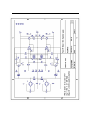
Placid BP Power Supply
User Manual
Revision 1.0
For PCB Revision 2.1.2
Twisted Pear Audio
Overview
The Placid BP is a shunt regulated bipolar DC power supply designed for low noise and excellent line and
load regulation. It is primarily intended for ±12-15VDC supplies using transformers with dual 12-15VAC
secondaries. It is important your read the manual prior to trying to use this power supply. Make sure you
understand how to adjust the output voltage and current before you do anything else. You could easily
destroy something if you do not know what you are doing. So be careful, and read the schematic and this
manual. This is not a difficult circuit to use, but it is not trivial so be careful. You can learn a lot from the
schematic. Take advantage of it. There is no shame in asking questions. Please ask them before you do
anything you might regret later.
Default Configuration
The supply is designed to be fed by either a single dual secondary transformer or a pair of single secondary
transformers. For the purposes of this manual we will assume you are aiming for ±15VDC rails and
~200mA per rail load current. The kit included parts are suitable for this setup. If you need more
current/voltage you may need to change some parts. This is covered later. We will also assume you have a
transformer with dual 15VAC secondaries rated at 15VA or more.
The 200mA supply current configuration should fit projects like powering the analog rails of a Buffalo32S
very well. It is very easy to configure the supply for other current demands by simply adjusting a few part
values. As always you can ask us for help if you have a special need. If you need more or less current I will
explain how to achieve it.
First Steps
The simplest and most accurate way to setup the supply is by using the provided variable resistors.
Populate the PCB as you normally would, stuffing components from shorted to tallest. Mount the TO-220
transistors to the large heat sinks with the included thermal paste and mounting hardware prior to soldering
them. You only need a thin film of thermal paste on the back of each transistor. The included packet should
be enough for more than ten transistors.
IMPORTANT!!! Prior to applying power or even wiring the transformers, adjust the CCS pots so
that the resistance across the CCS R positions (VR1 and VR2) is about 15Ω (caution: do not over-turn
the adjustor). Then adjust the VOUT pots (VR3 and VR4) to close to their maximum resistance which
should be ~2K.
It is easy to check the resistance of the pots by placing your DMM probes on the outer pads of the
potentiometers with the board turned upside down. Be careful adjusting the potentiometers. Do not turn the
adjustment screws beyond their stops.
Once you have completed the above steps, leave the outputs of the supply unconnected to any load. Now
connect it to the transformer secondaries: one secondary to AC1 and the other to AC2. Then apply power
and you should see some nice glowing LEDs and no smoke. You will need to adjust the output voltage next.
Adjust the potentiometers (VR3/VR4) for VOUT until the voltage at the output terminals is as desired. We
will assume 15V rails.
Now adjust the CCS pots (VR1/VR2) until the measured voltage across R1 and R2 are ~ 0.25V. The Placid
BP is now ready to supply current of up to 250mA.
You are now ready to connect the supply to your load. Power down, connect it to the load, and then power
up. Now re-check the output voltage. There should be no voltage sag. If there is some you may need to
increase the output current. The output current per rail is calculated as Voltage across RE divided by value
of RE where RE is either R2 for the positive rail and R1 for the negative rail. The supplied values for R1
and R2 are 1Ω making the calculation pretty easy. Every millivolt across those resistors is 1 milliamp of
supply current.
Now you are ready to fine tune the current sources. In the case of the IVY-III and most other Twisted Pear
analog stages 50-60mA of current headroom (the amount of current shunted by the shunt elements) is a very
good operating point. It is very easy to adjust and measure the amount of current being shunted. This is
current not used by the load. To measure the shunted current you simply carefully measure the voltage
across R13 and R14. With the load powered and operating adjust VR1 and VR2 and carefully measure the
voltage across R13 and R14. Adjust until this voltage is between .05VDC and .06VDC. I try to keep these
adjusted to the same point. Congratulations. You should now have your Placid BP running well.
Some Helpful Setup Tips
The voltage reference (VREF) used to regulate the supply normally is ~4V and in my prototype I am
measuring 4.06VDC. A little variation is normal because of variances in the LEDs and supply voltages after
rectification. You must measure the actual voltage at the output before you proceed to the use the supply.
The more gain you use the more the VREF variation will be apparent. The LED VREF will vary a small
amount with temperature. For this reason I tend to adjust the voltage to just under my desired maximum
output voltage. The VREF will tend to decrease voltage a bit as it warm so it will start slightly high and then
settle down little as it warms to a steady state. So if I know I want a maximum VOUT of 15VDC I will set the
supply VOUT to around 14.90VDC when warm to allow for the slightly higher value at startup.
The formula for the output voltage is this:
= ∗ 1 + where RF is R7 and R8 and RG is R3 and R4.
Here are some possible configurations using a fixed resistor to set VOUT. These assume the feedback
resistor value is 2K. When using a fixed output voltage you would omit VR3 and VR4.
RG (R3 & R4)
Approximate VOUT
Open
~ 4V
8.06K
~5V
4.02K
~6V
2K
~8V
1K
~12V
732R
~15V
A Few Advanced Tips
Advanced users who want to do something other than the default configuration should understand the
provided schematic. If you don't understand something then please ask for help before you go forward. If
you do understand the circuit well enough to be confident in changing things around a bit then here are
some tips.
If you need to supply > 500mA per rail you will want to make sure you use adequate heat sinks.
You can also substitute fixed resistors for the CCS potentiometers. Just do the calculations before hand or
temporarily install and measure the resistance across the potentiometers, and once your happy with the
current you can remove them and substitute .25W metal film fixed resistors. I would not try any output
current where the emitter resistors would need to be larger than .25W types.
If you are going to use transformers other than dual 12-15VAC secondaries, you will likely need to adjust
R11 and R12. You should aim for 5-10mA across them.