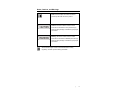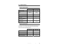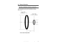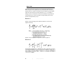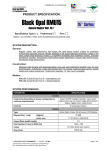
1
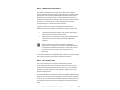
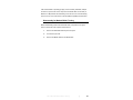
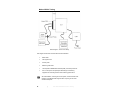
Model 7605 / Model 7606
Radiating Loop
&
Loop Sensor
User Manual
For MIL-STD-461D Tests
In Accordance With
Method RS101 of MIL-STD-462D
ETS-Lindgren L.P. reserves the right to make changes to any product described
herein in order to improve function, design, or for any other reason. Nothing
contained herein shall constitute ETS-Lindgren L.P. assuming any liability
whatsoever arising out of the application or use of any product or circuit
described herein. ETS-Lindgren L.P. does not convey any license under its
patent rights or the rights of others.
© Copyright 1999–2010 by ETS-Lindgren L.P. All Rights Reserved. No part
of this document may be copied by any means without written permission
from ETS-Lindgren L.P.
Trademarks used in this document: The ETS-Lindgren logo is a trademark of
ETS-Lindgren L.P.
Revision Record
MANUAL MODEL 7605/7606 MILSTD 461D RS101 | Part # 399222, Rev. B
ii
Revision
Description
Date
A
Initial Release
April, 1999
B
Rebrand
July, 2010
|
Table of Contents
Notes, Cautions, and Warnings ................................................ v About This Manual ................................................................... vii 1.0 Introduction .......................................................................... 9 About Model 7605 ........................................................................................ 10 About Model 7606 ........................................................................................ 10 References .................................................................................................. 11 ETS-Lindgren Product Information Bulletin ................................................. 12 2.0 Maintenance ....................................................................... 13 Annual Calibration ....................................................................................... 13 Service Procedures ..................................................................................... 13 3.0 Specifications..................................................................... 15 Electrical Specifications ............................................................................... 15 Physical Specifications ................................................................................ 15 4.0 Theory of Operation........................................................... 17 Schematic of 7605/7606 in Calibration Configuration.................................. 17 Model 7605 .................................................................................................. 18 Equation 1............................................................................................ 18 Equation 2............................................................................................ 18 Model 7606 .................................................................................................. 19 Equation 3............................................................................................ 19 Equation 4............................................................................................ 19 Equation 5............................................................................................ 20 Equation 6............................................................................................ 20 Equation 7............................................................................................ 20 Conversion Factors for Model 7606..................................................... 21 Equation 8............................................................................................ 22 5.0 MIL-STD-462D Method RS101 Testing ............................. 23 Operational Cautions ................................................................................... 23 Assembly for Calibration .............................................................................. 24 Method RS101 Calibration ........................................................................... 25 Required instrumentation..................................................................... 25 |
iii
About the Signal Source ...................................................................... 26 About the Measuring Instruments ........................................................ 27 About the Current Probe ...................................................................... 27 Calibration Steps ................................................................................. 28 Disassembly for Method RS101 Testing ..................................................... 29 Method RS101 Testing ................................................................................ 30 Start the EUT ....................................................................................... 31 Select Test Frequencies ...................................................................... 31 Equation 9 ................................................................................... 33 Testing the EUT ................................................................................... 34 Equation 10 ................................................................................. 34 Model 7606 Calibration Calculations ........................................................... 34 Calibration by Calculation .................................................................... 35 Equation 11 ................................................................................. 35 Equation 12 ................................................................................. 35 Equation 13 ................................................................................. 36 Equation 14 ................................................................................. 36 Traceability to NIST ............................................................................. 37 Appendix A: Warranty ............................................................. 39 iv
|
Notes, Cautions, and Warnings
Note: Denotes helpful information intended to
provide tips for better use of the product.
Caution: Denotes a hazard. Failure to follow
instructions could result in minor personal injury
and/or property damage. Included text gives proper
procedures.
Warning: Denotes a hazard. Failure to follow
instructions could result in SEVERE personal injury
and/or property damage. Included text gives proper
procedures.
See the ETS-Lindgren Product Information Bulletin for safety,
regulatory, and other product marking information.
|
v
This page intentionally left blank.
vi
|
About This Manual
Numbers enclosed in square brackets correspond to the references
listed in References on page 11.
•
This manual explains the theory of operation of the Model 7605
Radiating Loop and Model 7606 Radiating Sensor, and the use of the
set for MIL-STD-462D [1] electromagnetic interference (EMI) testing.
•
The scope of this manual includes only the theory of operation,
calibration, and use of Model 7605 and Model 7606 for EMI testing in
accordance with Method RS101 [2] of MIL-STD-462D.
•
The use of Model 7605 and Model 7606 for other purposes in
electromagnetic compatibility (EMC) testing is limited only by the
ingenuity of the user, but uses in addition to MIL-STD-462,
Method RS101 EMI testing are not included.
•
The international system of units (SI) is used throughout this manual.
Refer to IEEE Std 268 [3] for correct abbreviations and their proper
use, and IEEE Std 260 [4] for the proper use of units with the decibel
symbol (dB).
•
In general, definitions of EMC terms are contained in ANSI C63.14 [5]
and other electrical terms in IEEE Std 100 [6].
|
vii
This page intentionally left blank.
viii
|
1.0 Introduction
The ETS-Lindgren Model 7605 Radiating Loop and Model 7606 Radiating
Sensor are provided as a set, and are used together for the test equipment
calibration described in Method RS101 of MIL-STD-462D. Model 7605 is used
separately during susceptibility (immunity) testing of Equipment Under
Test (EUT).
Use the included nylon bolt to connect the Model 7605 and
Model 7606 together. Do not use a metallic bolt or calibration will be
inaccurate.
Shown unassembled
Shown assembled
Introduction
|
9
About Model 7605
•
Model 7605 is a 20-turn coil of AWG-12 enamel-insulated copper wire.
It is wound in a groove on a coil form made of a polytetrafluoroethylene
(PTFE) material. The average diameter of the coil is 12 cm (120 mm).
•
The coil form is extended to provide a built-in 5-cm spacer to keep the
coil at the required distance from the EUT. A slot with a threaded
screw hole is cut into the end of the spacer to attach the Model 7606.
•
The coil is used to expose EUT to magnetic fields in the range of 30 Hz
to 100 kHz. It produces a magnetic field that has a flux density of
7
9.5 x 10 picotesla per ampere (pT/A) of current flowing in it at an axial
distance of 5 cm (50 mm) from the center. In decibels, this is
160 dB(pT/A). The coil can carry 15 A rms (root mean square) of
alternating current with only ambient cooling.
About Model 7606
•
Model 7606 is a 4-cm (40-mm) diameter, electrostatically-shielded loop
antenna with 51 turns of 7-strand AWG-41 litz wire.
•
The Model 7606 is used to calibrate the Model 7605 and associated
instrumentation. It has a phenolic holder which mounts to the
Model 7605 to hold both windings parallel and coaxial to each other
with their centers precisely 5 cm apart. The holder of the Model 7606
has a 1/4–20 threaded hole to mount to a standard tripod.
•
The Model 7606 is terminated in a BNC connector near the end of the
holder. For test setup calibration, the Model 7605 and Model 7606 are
fastened together with a 3/8–16 nylon bolt.
10
|
Introduction
References
[1]
MIL-STD-462D, 11 January 1993, Military Standard Measurements of
Electromagnetic Interference Characteristics.
[2]
Method RS101, "Radiated Susceptibility, Magnetic Field, 30 Hz to
100 kHz," MIL-STD-462D, 11 January 1993, pp 103–108.
[3]
IEEE Std 268–1992, American National Standard for Metric Practice.
(ANSI)
[4]
IEEE Std 260–1978 (Reaffirmed 1985), IEEE Standard Letter Symbols
for Units of Measurement. (ANSI)
[5]
ANSI C63.14–1992, American National Standard Dictionary for
Technologies of Electromagnetic Compatibility (EMC), Electromagnetic
Pulse (EMP), and Electrostatic Discharge (ESD).
[6]
IEEE Std 100–1992, Standard Dictionary of Electrical and Electronics
Terms. (ANSI)
[7]
Ramo, Simon, and John R. Whinnery, Fields and Waves in Modem
Radio, Second Edition, John Wiley & Sons, Inc. NY, 1953, (©General
Electric Company 1944, 1953), pp 90–91.
[8]
Jasik, Henry, Editor, Antenna Engineering Handbook. McGraw-Hill, 1961,
p 6–2.
[9]
MIL-STD-461D, 11 January 1993, Military Standard Requirements for the
Control of Electromagnetic Interference Emissions and Susceptibility,
pp 40–41.
[10]
MRP-P 1990:8, Testing Visual Display Units, Draft, National Council for
Metrology and Testing, Sweden.
Introduction
|
11
ETS-Lindgren Product Information Bulletin
See the ETS-Lindgren Product Information Bulletin included with your shipment
for the following:
12
•
Warranty information
•
Safety, regulatory, and other product marking information
•
Steps to receive your shipment
•
Steps to return a component for service
•
ETS-Lindgren calibration service
•
ETS-Lindgren contact information
|
Introduction
2.0 Maintenance
Before performing any maintenance,
follow the safety information in the
ETS-Lindgren Product Information
Bulletin included with your shipment.
Maintenance of the Model 7605 and Model 7606 is limited to external
components such as cables or connectors. If you have any questions concerning
maintenance, contact ETS-Lindgren Customer Service.
Annual Calibration
See the Product Information Bulletin included with your shipment for information
on ETS-Lindgren calibration services.
Service Procedures
For the steps to return a system or system component to ETS-Lindgren for
service, see the Product Information Bulletin included with your shipment.
Maintenance
|
13
This page intentionally left blank.
14
|
Maintenance
3.0 Specifications
Electrical Specifications
Frequency Range:
Wire:
Model 7606
30 Hz–100 kHz
30 Hz–100 kHz
AWG-12
7-41
Enameled Copper
Litz Copper
20
51
15 A Continuous
NA
Banana Jack (Pair)
Type BNC Female
40 mΩ
3.9 Ω
71.8 µH
175 µH
Number of Turns:
Maximum Input Current:
Connector:
Model 7605
Resistance of Winding
(Approximate):
Inductance
(Approximate):
Physical Specifications
The windings on both models have square cross sections with dimensions of
approximately 12 mm for the Model 7605 Radiating Loop and approximately
3.175 mm for the Model 7606 Radiating Sensor.
Model 7605
Model 7606
5.89 cm (2.32 in)
13.46 cm (5.30 in)
Base Width:
NA
5.08 cm (2.00 in)
Base Depth:
NA
1.90 cm (0.75 in)
12.0 cm
4.0 cm
Height:
Mean Loop Diameter:
Specifications
|
15
This page intentionally left blank.
16
|
Specifications
4.0 Theory of Operation
Schematic of 7605/7606 in Calibration Configuration
The following illustration shows the Model 7605 Radiating Loop and the
Model 7606 Radiating Sensor as loops or coils separated by a calibration
distance of 5 cm.
Theory of Operation
|
17
Model 7605
Model 7605 is used alone to produce an AC magnetic field to test Equipment
Under Test (EUT) for susceptibility (immunity) to magnetic fields in the frequency
range from 30 Hz to 100 kHz. It consists of 20 turns of AWG-12 enamel-insulated
copper wire close-wound with an average diameter of 12 cm. It is capable of
carrying 15 A rms, but if this level of coil current is sustained for long periods, the
coil will become warm. It has a coil resistance of approximately 40 mΩ and an
inductance of approximately 71.8 µH.
EQUATION 1
Equation 1 derived from [7] gives the relationship between coil current and
magnetic flux density.
Equation 1 may be simplified for computation as shown in equation 2.
EQUATION 2
18
|
Theory of Operation
Model 7606
Model 7606 is used with Model 7605 to calibrate the 7605 and other
instrumentation used in tests. With 51 turns of wire in a 4-cm diameter loop, it
2
has an effective area of 640 cm (an effective diameter of 28.6 cm), improving
the sensitivity of measurements with a given instrument by more than 30 dB over
a small, single-turn loop. The response is tabulated in the Conversion Factors for
Model 7606 table on page 21 (and is proportional to the frequency shown in
Figure RS101-1 in Method RS101 of MIL-STD-462D).
The voltage induced in the loop, ei, is proportional to the area of the loop, the
number of turns, the frequency, and the average flux density within the area of
the loop. Equation 3 derived from [8] gives this relationship.
EQUATION 3
For the Model 7606, the open-circuit loop-terminal induced voltage in microvolts
for a magnetic flux density in picotesla is given in equation 4.
EQUATION 4
The general equation for the conversion factor is given by equation 5 and
equation 6, and includes the effects of loop impedance and load impedance.
Theory of Operation
|
19
EQUATION 5
EQUATION 6
For the Model 7606, equation 6 becomes equation 7.
EQUATION 7
The values in the following table were calculated from equation 5 and equation 7
using a 50 Ω load and a 600 Ω load. (These values are the same as in
Figure RS101-1 in MIL-STD-462D.)
20
|
Theory of Operation
CONVERSION FACTORS FOR MODEL 7606
This table shows that below 15 kHz there is less than 1 dB difference between
the values of the conversion factors for the loop loaded in 50 Ω and in 600 Ω
(open circuit), and over most of the range the difference is less than 0.6 dB. To
find values of the correction factor between these values, use the interpolation in
equation 8.
Conversion Factor, dB(pT/µV)
Frequency (kHz)
50 Ω
600 Ω
0.03
99.01
98.41
0.1
88.56
87.96
1
68.56
67.96
3
59.03
58.42
7
51.41
51.06
10
48.73
47.96
13
46.57
45.68
15
45.42
44.44
17
44.44
43.35
20
43.20
41.94
23
42.18
40.73
27
41.07
39.34
30
40.39
38.43
35
39.46
37.09
40
38.72
35.94
45
38.13
34.92
50
37.66
34.01
70
36.46
31.13
100
35.66
28.10
Theory of Operation
|
21
EQUATION 8
22
|
Theory of Operation
5.0 MIL-STD-462D Method RS101 Testing
Before connecting any components, follow the
safety information in the ETS-Lindgren
Product Information Bulletin included with your
shipment.
The normal design application of the Model 7605 Radiating Loop and
Model 7606 Radiating Sensor is the MIL-STD-462D Method RS101 EMI testing.
Additional applications are possible, but only the application to Method RS101 is
discussed here.
Method RS101 requires two distinct activities: test setup calibration and exposure
of the Equipment Under Test (EUT) to specified magnetic flux densities.
Operational Cautions
Large magnetic fields are produced during
testing, particularly at low frequencies. They are
capable of affecting calculators and watches,
and at the RS101 worst-case limits, they exceed
the levels which the Swedish government [10]
has set for video display terminals. Therefore,
take these precautions:
•
Keep all calculators, watches, rings, and
other metallic objects at least one meter
from the Model 7605 during testing.
•
Keep your head and torso at least 90 cm
from the Model 7605 during testing below
400 Hz.
The Model 7606 may be damaged by large
currents, so do not connect it to the
signal source, and do not leave it in place
during testing.
MIL-STD-462D Method RS101 Testing
|
23
Assembly for Calibration
For test setup calibration, Model 7605 and Model 7606 are assembled together.
When assembled, the two loops are parallel to each other and coaxial with their
centers precisely 5 cm apart.
Do not over tighten the nylon bolt. Tighten it to
only finger tight; do not use a wrench.
Over tightening may cause the bolt to break,
blocking the bolt hole and making calibration
impossible.
1. Place the Model 7606 into the slot
in the body of the Model 7605, with
the BNC connector positioned
outside Model 7605 and pointing
upward.
2. Insert the 3/8–16 nylon bolt. Tighten
to finger tight.
24
|
MIL-STD-462D Method RS101 Testing
Method RS101 Calibration
Mount the Model 7605/Model 7606 assembly on a non-metallic tripod. This helps
prevent interaction between the assembly and the surroundings, and allows the
operator to be hands-free near the instrumentation.
Block Diagram – Calibration Test Setup
During calibration, keep the assembly several diameters away from metal
objects. Space the current probe and other instrumentation at least one meter
from the assembly to keep it from the influence of the Model 7605.
REQUIRED INSTRUMENTATION
•
Model 7605/Model 7606 assembly
•
Signal source—see page 26 for more information
•
Two measuring instruments—see page 27 for more information
•
Current probe—see page 27 for more information
MIL-STD-462D Method RS101 Testing
|
25
ABOUT THE SIGNAL SOURCE
The signal source may be a signal generator followed by a power amplifier or
current amplifier. The signal generator may be a manual signal generator, a
tracking generator (part of a spectrum analyzer or EMI meter), or a
computer-controlled signal generator. A 30 W power amplifier with an output
impedance of 0.5 Ω will drive the Model 7605 to about 15 A and produce up to
183 dB(pT) at the end of the built-in 5 cm spacer. When the amplifier is set to the
30 W output level, it produces a current of almost 15 A in the Model 7605, but the
actual amplifier power output is only about 9 W; the 30 W amplifier is needed to
be able to provide enough current from a 0.5 Ω source.
At the lower end of the frequency range, it would be better to use an amplifier
with output impedance lower than 0.5 Ω. For example, if the amplifier had a
source impedance of only 0.125 Ω, the power output capability would need to be
only 9.5 W. However, amplifiers and matching transformers to provide an output
impedance of 0.125 Ω are not readily available in the EMC test equipment
marketplace, but those providing 0.5 Ω are; they are typically found in an
EMC laboratory equipped for MIL-STD-462 testing.
The power amplifier and coupling transformer used for Method CS101 tests may
be used for RS101 tests, but the amplifier does not need as much power for
RS101 tests. Higher impedance amplifiers may be practical at the higher
frequencies where much less current is needed to produce the flux densities
required in the RS101 EMI susceptibility tests.
26
|
MIL-STD-462D Method RS101 Testing
ABOUT THE MEASURING INSTRUMENTS
The measuring instruments can be radio-noise or EMI meters, calibrated
receivers, spectrum analyzers, or other tunable (narrowband) voltmeters. These
instruments must be accurately calibrated with appropriate correction factors
available across the frequency range. A number of possible instruments are
available. Some instruments, for example, certain automatic spectrum analyzers,
may require no correction factors, since they self-calibrate and internally
generate and apply a correction factor at each frequency.
A single instrument can be used for both Measuring Instrument A and
Measuring Instrument B indicated in the illustration on page 25. If this is done:
•
The Model 7606 should be loaded by a 50 Ω dummy load while the
output of the current probe is being measured.
•
More importantly, the output of the current probe must be loaded by a
50 Ω dummy load when the output of the Model 7606 is being
measured.
Failure to load the current probe in 50 Ω while the measuring
instrument is not connected to it may result in unpredictable changes
in the impedance inserted into the line by the current probe. This may
then cause an unknown change in the current flowing in the
Model 7605.
For convenience during the susceptibility testing of the EUT, a spectrum analyzer
with a tracking generator may be used for measuring instrument A.
ABOUT THE CURRENT PROBE
The current probe may be a low-frequency EMI measuring clamp-on
current probe designed to cover the frequency range from 30 Hz to 100 kHz;
several manufacturers offer this type of probe. The accuracy of the individual
calibration is important because it is a key element in setting the test current
during EMI measurements.
The transfer admittance (or impedance) should be individually calibrated over the
frequency range. Usually, the probe calibration by the manufacturer is adequate,
but do not rely on a probe that has a calibration reported at a single frequency or
has a single conversion factor that is to be applied across the entire frequency
range.
MIL-STD-462D Method RS101 Testing
|
27
CALIBRATION STEPS
1.
Set the signal source to a frequency of 1 kHz and adjust the output to
provide a magnetic flux density of 110 dB(pT) as determined by the
reading obtained on instrument A and the relationship
B = 160 dB(pT/A). This requires a current of -50 dB(A) or 3.16 mA.
To determine the current, algebraically add the current probe
correction factor in dB(S) to the reading in dB(mV) on instrument A; for
example:
2.
Measure the voltage output in dB(µV) from the Model 7606 on
instrument B.
3.
Verify that the output from the Model 7606 is 42 dB(µV) ±3 dB, and
record this value.
If the output from Model 7606 is not within ±3 dB of 42 dB(µV), verify the source
current is set correctly, and then look for other causes. Some possible causes
are:
•
Inaccuracy in either or both measuring instruments.
•
Malfunction of either or both measuring instruments.
•
Inaccuracy in the current probe.
•
Loose clamping or other malfunction of the current probe.
•
Damage to the current probe.
•
Magnetic-field coupling between Model 7605 and the current probe or
measuring instruments.
•
Loose fit between Model 7605 and Model 7606, or other incorrect
assembly.
•
•
Damage to Model 7605 or Model 7606.
Metallic objects, particularly magnetic materials, in close proximity to
Model 7605 and Model 7606.
28
|
MIL-STD-462D Method RS101 Testing
If all instrumentation is operating properly and is accurately calibrated, readjust
the source to produce the correct output from the Model 7606. Use the ratio (or
difference in dB) between the initial setting of the source to the corrected setting
of the source as a correction factor in the later EMI susceptibility measurements.
Disassembly for Method RS101 Testing
Before disassembling Model 7605 and Model 7606, verify that the test signal
source is turned off or the output is reduced to zero.
1.
Remove the 7605/7606 assembly from the tripod.
2.
Unscrew the nylon bolt.
3.
Remove the Model 7606 from the Model 7605.
MIL-STD-462D Method RS101 Testing
|
29
Method RS101 Testing
Block Diagram – RS101 Test Setup
This diagram shows EUT and these items of instrumentation:
•
Model 7605
•
Test signal source
•
Current probe
•
Measuring instrument
•
Line Impedance Stabilization Network (LISN) in the EUT power line
•
One or more pieces of input/output stimulating and monitoring
equipment for exercising the EUT and monitoring performance
All instrumentation, including the current probe, must be outside of the
influence of the Model 7605 magnetic field. A spacing of one meter
should be adequate.
30
|
MIL-STD-462D Method RS101 Testing
Testing EUT for susceptibility (immunity) consists of three processes: starting the
EUT, selecting test frequencies (may be done semi automatically), and testing
the EUT at the selected frequencies (done manually).
START THE EUT
Turn on the EUT, allow it to stabilize, and then verify it is operating properly.
Make sure the input/output stimulation and monitoring equipment is operating
satisfactorily.
SELECT TEST FREQUENCIES
Testing – Showing Application of Model 7605
1.
Position the Model 7605 so that the built-in spacer is flat against one
surface of the EUT. This places it parallel to and 5 cm from the EUT.
MIL-STD-462D Method RS101 Testing
|
31
2.
Drive the Model 7605 with sufficient current to produce a magnetic flux
density 10 dB greater than the applicable limit in MIL-STD-46ID [9], but
do not exceed 15 A; for example, 183 dB(pT). The following chart
shows the Model 7605 coil current at the RS101 limits.
3.
Scan the frequency range from 30 Hz to 100 kHz. The scan rate may
be three times faster than the rates specified in Table III of
MIL-STD-462D.
In the 30 Hz to 100 kHz range the specified rates are 0.02f0
per second for analog scans and 0.01f0 steps (1% steps) for stepped
scans; so for these frequency selecting scans, the scan rates can be
0.06f0 per second for analog scans and 3% steps for stepped scans.
32
|
MIL-STD-462D Method RS101 Testing
Stepped scans must dwell at each frequency for one second. f0 is the
tuned frequency, not the starting frequency. Usually, for analog scans,
the frequency range is broken into octave or decade bands and the
scan rate is changed at each band. The following table shows
suggested bands and analog scan rates. For stepped scans, the
frequencies may be computed using equation 9.
Frequency Band
Analog Scan Rate
Total Scan Time
30 Hz–100 Hz
2 Hz/s
35 s
100 Hz–200 Hz
8 Hz/s
12.5 s
200 Hz–400 Hz
17 Hz/s
11.8 s
400 Hz–700 Hz
32 Hz/s
9.3 s
700 Hz–1.5 kHz
61 Hz/s
13.1 s
1.5 kHz–3 kHz
127 Hz/s
11.8 s
3 kHz–6 kHz
250 Hz/s
12 s
6 kHz–10 kHz
460 Hz/s
8.7 s
10 kHz–20 kHz
850 Hz/s
11.8 s
20 kHz–40 kHz
1.7 kHz/s
11.8 s
40 kHz–100 kHz
3.8 kHz/s
15.9 s
Suggested Scan Rates for Analog Scanning
EQUATION 9
4.
If susceptibility is noted, select three or more test frequencies per
octave at frequencies where susceptibilities are present. For example,
if five frequencies within an octave show susceptible responses, select
at least three of them for further testing. The three selected should be
those with the maximum indication of susceptibility.
MIL-STD-462D Method RS101 Testing
|
33
5.
Reposition the Model 7605 successively to a location in each 30 cm by
30 cm area on each surface of the EUT and repeat the previous steps.
6.
From the total set of data where susceptibility was noticed, select three
frequencies in each octave of the frequency range from 30 Hz to
100 kHz where susceptibility was found.
TESTING THE EUT
At each frequency determined as a result of selecting test frequencies, apply the
current to the Model 7605 that corresponds to the applicable limit in
MIL-STD-461D. For accuracy in this process, calculate the required loop current
using equation 10. Move the loop to search for all possible locations of
susceptibility, including cables, connectors, cabinet seams, vents, and so on.
EQUATION 10
Model 7606 Calibration Calculations
The Model 7606 is designed to conform to MIL-STD-462D. This sensor is
electrically very small, which permits performance calculation based on
geometry. In the table on page 21 the performance is shown in the form of a
conversion factor which is used to convert the output voltage, in dB(µV), to the
magnetic flux density, in dB(pT), of the field in which the coil is immersed.
The tolerances in manufacturing are a maximum of 0.05 mm (0.002 inches).
These tolerances in worst-case combination cause a maximum error of ±0.06 dB.
The best accuracy with which the conversion factor can be measured is ±1 dB,
and larger errors are probable. Therefore, the conversion factor is not measured,
but is instead calculated to provide the best possible accuracy (absolute error
≤0.06 dB).
34
|
MIL-STD-462D Method RS101 Testing
CALIBRATION BY CALCULATION
Following are the equations used in calculation of Model 7606 performance,
along with a sample calculation.
The absolute value of the ratio of the magnetic flux density to the voltage across
the connected load, BVL, is given by equation 11.
EQUATION 11
The coil resistance, Rc, is found from the length of wire in the coil and the unit
resistance of the wire; or, it can be measured with a low-resistance bridge. The
length of the wire is the product of the average circumference of the winding and
the number of turns. This is shown in equation 12.
EQUATION 12
The coil inductance, L, is found from equation 13.
MIL-STD-462D Method RS101 Testing
|
35
EQUATION 13
The ratio |B/VL| is put in decibels by equation 14 to become the correction factor,
CF.
EQUATION 14
Sample Calculation:
The maximum uncertainty because of dimensional tolerances is ±0.06 dB;
therefore, this calculated correction factor has a range of 98.95 dB to 99.07 dB.
For ordinary measurement work, such as the measurements for RS101, it is
reasonable to round this correction factor to 99.0 dB.
36
|
MIL-STD-462D Method RS101 Testing
TRACEABILITY TO NIST
The traceability to NIST is through the mechanical measurements and
mechanical calibration of the tools used to manufacture the Model 7606. It can
be proven mathematically that for such an electrically small sensor, the
performance can be accurately calculated based on the dimensions of the
sensor. Thus, the traceability of the manufacturing tools to NIST provides
traceability of the electrical performance of the sensor to NIST.
MIL-STD-462D Method RS101 Testing
|
37
This page intentionally left blank.
38
|
MIL-STD-462D Method RS101 Testing
Appendix A: Warranty
See the Product Information Bulletin included with your shipment for
the complete ETS-Lindgren warranty for your Model 7605 Radiating
Loop and Model 7606 Radiating Sensor.
DURATION OF WARRANTIES FOR MODEL 7605 / MODEL 7606
All product warranties, except the warranty of title, and all remedies for warranty
failures are limited to two years.
Product Warranted
Duration of Warranty Period
Model 7605 Radiating Loop
2 Years
Model 7606 Radiating Sensor
2 Years
Warranty
|
39