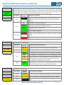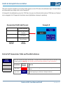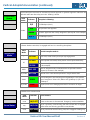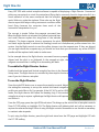
1
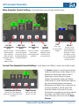
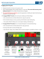
GRT Autopilot
WARNING: See GRT Autopilot Installation Manual and Autopilot Checkout Procedure for information on
wiring and switch configurations and post-installation testing. This guide details use of the autopilot when
a GRT pitch servo, roll servo, engage/disengage switch and external servo power switch are installed.
General Color Coding
Yellow - The AP is not following a navigation source. Examples: Heading Mode (HDG), all Autopilot OFF
indications, Vertical Speed or Heading Hold.
Red - Critical labels are red. Examples: AP emergency functions (S&L and 180° turn), GPS signal or glideslope
is lost while on approach, missed approach mode without a defined target altitude, pitch suspended (SUSP)
and pitch servo disengaged with excessive bank angle.
Green - Labels and bearing pointers associated with GPS navigation
White- Labels and bearing pointers associated with primary VHF radio; VOR, Localizer, or ILS
Cyan - Labels and bearing pointers associated with a secondary VHF radio if installed
Black - Annunciator labels for items that are pending
Magenta- GPS course, waypoint balloons
Dark Magenta- Heading bug when coupled to autopilot (HDG mode)
Vertical
Autopilot
Annunciators
Lateral
Autopilot
Annunciators
Autopilot navigation and mode softkeys appear across the bottom.
Horizon HXr User Manual Draft
Revision A1
GRT Autopilot Operation
Main Autopilot Control Softkeys- (Press Right Knob to access from HOME screen)
LAT A/P
VERT A/P
ARM
Lateral Autopilot Vertical Autopilot
Select Approach
Modes
Modes
Type
Choose what a/p
Choose whether to Tells a/p to expect
follows laterally
use Vertical Speed,
and capture
HDG- Heading
Airspeed or Vertical selected approach
ENAV-Electronic Command/Glideslope
guidance
Navigation (GPS or for climbs/descents
VOR/LOC)
GNAV-IFR GPS
SAP
EXIT
SEL ALT
Synthetic
Approach
Choose ARM to
load SAP. System
will then ask for
runway selection.
Press to go
back to HOME
softkeys
Turn knob to set
Altitude Bug and
Altitude Select box.
Push knob to Enter
and adjust vertical
rate to climb/descend
to selected Altitude.
(see Second Tier)
Second-Tier Autopilot Control Softkeys- (Press Right Knob TWICE to access from HOME screen)
Climb/Descent Presets
Flight Director
Choose one of the displayed
preset rates to execute the climb
or descent.
Press to turn Flight
Director on or off.
The preset airspeed or vertical speed choices
change as vertical a/p modes change. In this
example, an altitude was dialed in that is
higher than current altitude, so these
softkeys automatically display the default
climb presets. If a lower altitude was dialed in,
they would display descent rate presets.
Alternatively, turn Right Knob to manually set
a custom airspeed or vertical speed. See
Autopilot Presets in this section for more
information on programing and using vertical
a/p presets. See Flight Director section for
more information on how to use the Flight
Director.
Horizon HXr User Manual Draft
Revision A1
GRT Autopilot Operation
Engaging the Autopilot
1. Engergize servo(s) by turning on servo power switch.
2. Press engage/disengage switch, typically located on control stick. The aircraft will maintain present
heading and pitch and the softkeys illustrated below will appear.
3. To engage the Emergency functions, press the appropriate red softkey and adjust throttle setting as
necessary to maintain level flight.
3. To engage HDG/ALT function (fly to and capture Heading and Altitude Bugs):
a. Enter desired altitude into Altitude Selection Box using the right knob;
b. Enter desired heading by turning or pressing the left knob to adjust Heading Bug;
c. Press yellow HDG/ALT softkey to fly to and capture heading and altitude bugs.
4. To engage NAV/ALT function (fly to and capture Navigation Course and Altitude Bug):
a. Enter desired altitude into Altitude Selection Box using right knob;
b. Intercept NAV radial or activate GPS flight plan
c. Press NAV/ALT softkey–This is GREEN if GPS is the active navigation and WHITE if VOR/LOC is active.
Left Knob:
Push to sync
heading bug
with current
heading.
Turn to adjust
heading bug.
HDG/ALT:
Follow selected
heading and
altitude. Set
bugs before
pressing.
NAV/ALT:
S&L HOLD ALT
Press to fly to
& HDG:
active NAV or
Engages a/p to
GPS course and
roll wings level,
selected altitude. then pitch to hold
Set course and
present altitude.
bugs before
Unusual attitude
pressing.
recovery.
Horizon HXr User Manual Draft
180° ALT HLD:
Press to hold
present altitude
and enter a 180
degree turn. For
level exit from
inadvertent IMC.
Revision A1
GRT Lateral Autopilot Operation
When the servos are powered on and A/P is engaged, use the following procedures from any HOME screen.
Follow a Heading
1. Turn Left Knob to adjust heading bug to desired heading; Or press Left Knob to set heading bug to
current heading.
If LA/P is already in HDG mode, the aircraft will bank to follow the heading bug.
If A/P is in ENAV mode:
2. Press Right Knob to activate A/P softkeys.
3. Press LAT A/P softkey to highlight HDG. Press EXIT to engage and exit back to HOME screen. Autopilot
will enter HDG MODE and follow the heading bug.
4. Adjust heading using the Left Knob to guide the aircraft using the heading bug, such as for ATC vectors.
TIP: The autopilot will always bank in the direction of the shortest distance to the
selected heading. Make all heading bug adjustments that are more than 180 degrees in
two or more smaller increments to “guide” it in the correct direction.
Heading Bug
position
Heading mode
LA/P indication
In this example, the heading
bug is set to 124° and the
Lateral A/P is engaged in
heading mode. The aircraft
is about to initiate a turn
toward the heading bug.
(Demo unit screnshot; The
turn is instantaneous in
actual flight.)
Heading Bug is
dark magenta
when A/P is in
HDG mode;
otherwise white.
Press to select
HDG mode
Horizon HXr User Manual Draft
Revision A1
GRT Lateral Autopilot Operation
Track a GPS Course (Internal Flight Plan)
1. For best results, start off in HDG mode to avoid abrupt course changes when flight plan is activated.
1. Enter GPS waypoint(s) using a Direct-To or Sequence Mode, creating an internal flight plan.
2. Press OBS/CDI softkey to activate Navigation Source selection softkeys.
3. Press softkey beneath the appropriate Nav Source (GPS1 or GPS2). The source driving the autopilot
is underlined in green. GPS1 (or 2) will appear in the LA/P Nav Source annunciator box. GPS course
will appear as a Course Selection Needle on the HSI.
4. Press Right Knob to go to HOME page, then again to activate A/P menu.
5. If A/P is in HDG mode, press LAT A/P softkey to highlight ENAV. Press EXIT to engage and exit back
to HOME screen. Autopilot will enter ENAV or EFIS Navigation mode and follow the GPS flight plan.
TIP: For smooth operation, make sure the aircraft is on the GPS course before engaging ENAV mode, as it may
roll rapidly to intercept the course.
GPS WaypointAirport ID
ENAV mode
LA/P indication
In this example, the
LA/P is set for ENAV
mode, following the
synthetic approach for
Runway 08 at Big Bear
City, CA (L35).
Note white
Heading Bug in
ENAV mode;
set to missed
approach
heading.
Press to select
ENAV mode
Horizon HXr User Manual Draft
Revision A1
GRT Lateral Autopilot Operation
Track a VOR/LOC Course
1. For best results, engage HDG mode of autopilot. (This will allow smooth adjustment of OBS course.)
2. Tune VOR or ILS frequency into the Nav radio.
3. Press OBS/CDI softkey to activate Navigation Source selection softkeys.
4. Press softkey beneath the Nav source to be tracked (NAV1, NAV2). For a VOR, adjust OBS course by
turning Right Knob. ILS inbound courses are automatically tuned on the HSI.
5. Press Right Knob to return to Home, then press it again to access Autopilot control softkeys.
6. Press LAT A/P softkey to highlight ENAV. The autopilot will fly to and capture the selected radial. Note
that the ILS CDI replaces the horizontal bars of the attitude indicator if the selected frequency is a localizer.
TIP: For smooth operation, make sure the aircraft is on a shallow intercept course before engaging
ENAV mode, as it may roll rapidly to intercept the course.
Localizer
Frequency
Nav source indication.
Note Synthetic Approach
for Runway 5 (SAP05) in
standby window. Load the
synthetic approach for the
runway to display HITS
boxes on the ILS course.
Horizon HXr User Manual Draft
Revision A1
Autopilot Presets
Setting Up the Presets
The HXr can store and recall preset airspeeds and rates for autopilot-coupled altitude changes.
Customize your autopilot with 2 values for each of the following:
Ÿ Climb IAS
Ÿ Climb VS
Ÿ Descent IAS
Ÿ Descent VS
Before using the autopilot, set a gentle cruise climb/descent and a more aggressive rate for each.
1. Press MORE > Set Menu > Primary Flight Display
2. Scroll to Climb IAS Preset #1 and begin entering speed/rate settings appropriate for your aircraft.
3. SAVE your settings.
Flying the Autopilot Using Presets
In flight, choose which presets to use during climbs and descents. The default setting, AUTO, presents
airspeed (IAS) presets for climbs and Rate (VS) presets for descents. To change this:
1. From the HOME screen, press the right knob to access the autopilot softkeys shown below.
Alternatively, turn the right knob, which will also begin the process of changing the altitude bug.
2. Press the VERT A/P softkey to manually select AUTO, VS (vertical speed), ASPD (airspeed), or VNAV
(vertical navigation/approach).
Horizon HXr User Manual Draft
Revision A1
Autopilot Presets
To Climb/Descend With Autopilot Engaged:
1. From the HOME screen, turn the right knob to enter a new altitude into the Altitude Preselect
Window/Altitude Bug.
2. Press the knob to set it.
3. If the new altitude is higher than the present altitude, a message will appear on the PFD screen asking
if you would like to climb at the suggested (last used climb) airspeed. If the new altitude is lower, it
will ask if you would like to descend at the suggested (last used descent) vertical speed. Then perform
one of the following actions:
a. Press the right knob to accept the displayed airspeed/vertical speed and begin the altitude change.
b. Press one of the preset airspeed/vertical speed softkeys displayed on the bottom of the screen,
then press the right knob to acknowledge and begin the altitude change.
c. Turn the right knob to set a any airspeed/vertical speed, then press it again to begin the altitude
change.
d. Press CANCEL to abandon the altitude change and go back to the HOME screen softkeys.
Descent Rate Presets
Press Knob to Begin Altitude Change
Horizon HXr User Manual Draft
Revision A1
Lateral Autopilot Annunciators
The LA/P (lateral autopilot) annunciator fields appear on the PFD above the airspeed tape. The field labels
are illustrated here, along with a color Example A.
Example A
Annunciator Field Label Format
Target
Navigation Source
A/P Mode
Servo Status
Pending
Column
Active
Column
Lateral A/P Annunciator Fields and Possible Indications
Target
or “Steer-To.” Where the lateral A/P is going. This can be a heading, GPS waypoint, airport identifier,
VHF frequency, etc. Possible indications include:
LA/P Mode
Indicator
Example
HDG HLD
---°
HDG
166°
KGRR
Steer To:
No steer-to target is defined.
Selected heading (166° in Example A above)
Active GPS Waypoint ID
166°
Reversion to last GPS course after passing last waypoint in the
flight plan
119.1
VHF NAVAID frequency before ILS or VOR approach is armed
ENAV
GRR
VHF NAVAID frequency after ILS or VOR approach is armed
Horizon HXr User Manual Draft
Revision A1
Lateral Autopilot Annunciators (continued)
Navigation
Source
The navigation source the A/P is tracking. This can be VOR, ILS, LOC, GPS, or SAP (synthetic approach).
Synthetic Approach indication will also display the runway number. Inactive or armed nav source labels
in the Pending column are black with white lettering. If a Nav source is selected on the OBS/Nav Source
page but the A/P is in heading mode, that source will appear in the Pending column.
LA/P Mode
Indicator
Example
Lateral A/P is tracking:
LOC
(Pending column only) Armed approach activates when aircraft is in
range; LA/P mode automatically switches to ENAV when approach is
captured.
LOC
VHF NAVAID (can also be VOR or ILS).
HDG
SAP05
Lateral portion of GPS-derived Synthetic Approach. Note runway
designation. (This example is SAP for Runway 5.)
GPS1
Flight plan or Direct-To GPS course
ENAV
LPV
GS Lost
any mode
GPS1 Lost
GPS LPV precision approach
VHF signal lost during approach. Appropriate label is displayed for each
flagged or inop VHF component (GS, LOC, VOR, etc). Displays in Pending
column.
GPS signal lost. Displays in Pending column.
Indicates lateral command mode.
LA/P Mode
LA/P Mode
Indicator
Example
Lateral A/P mode definitions are:
–
HDG HLD
Heading Hold- Holds current heading upon a/p engagement.
HDG
HDG
ENAV
”EFIS Navigation.” A/P follows active GPS course (Internal Flight Plan).
ENAV
“EFIS Navigation.” A/P follows active VHF course as displayed on EFIS.
CRS
Mode is ENAV but no valid GPS flight plan or VHF course exists. A/P
holds last known course track, which can be adjusted using right
knob (OBS) when CDI/OBS menu is activated.
ENAV
GNAV
Heading Mode. A/P follows Heading Bug.
GNAV
GPS Navigation (meaning External GPS, or “not” the EFIS). This is a
“pass-through” mode in which a connected external GPS navigator
controls the autopilot directly using an External Flight Plan.
Indicates servo activation level.
Servo Status
LA/P Mode
Indicator
Example
Servo power & activation:
none
LA/P-OFF
Power to the servo is disconnected. Emergency modes unavailable.
any
LA/P-ON
Servo is powered, communicating with the EFIS; LA/P is engaged.
none
LA/P-Stby
Servo powered & communicating; LA/P NOT engaged. Pending
only.
Horizon HXr User Manual Draft
Revision A1
Vertical Autopilot Annunciators
The VA/P (vertical autopilot) annunciator fields appear on the PFD above the altimeter tape. The field labels
are illustrated here, along with a color Example B.
In Example B, the altitude bug is set for 7500 feet, the a/p is in Altitude Hold mode at 7500 feet, and Vertical
a/p is engaged. An ILS approach has been armed (glideslope intercept is pending).
Example B
Annunciator Field Label Format
Target Altitude
Vertical Navigation
Source
A/P Mode
Servo Status
Pending
Column
Active
Column
Vertical A/P Annunciator Fields and Possible Indicators
Target
Altitude
Where the vertical A/P is going, MSL altitude. In VNAV mode, this field contains Decision Altitude if one
has been specified. (Warning: A/P will NOT level off at Decision Altitude–it is just a reminder.)
VA/P Mode
Indicator
Example
any mode
----
Dashes- No altitude target is defined. Color corresponds to Nav
source.
any mode
7500
Altitude Bug/Target (7,500 feet in Example A above)
Steer To:
Horizon HXr User Manual Draft
Revision A1
Vertical Autopilot Annunciators (continued)
Vertical Nav
Source
Present when pilot has armed or activated a precision approach or synthetic approach. Indicators are
black with white text when they are in the “Pending” column.
VA/P
Mode
Indicator
Autopilot is following:
G/S
ILS Glideslope (Nav 1).
LPV
LPV precision GPS approach
VNAV
SAP08
Synthetic Approach with runway designation (Runway 08 in this example)
G/S-2
ILS Glideslope (Nav 2)
Indicates whether vertical A/P is engaged and how it is controlling the airplane.
Vertical A/P
Mode
VA/P
Mode
Indicator
Vertical Autopilot mode is:
–
PIT HLD
Pitch Hold; Holds current pitch upon a/p engagement
VS HLD
Vertical Speed Hold mode; holds present vertical speed indefinitely.
VS-500
VS or Vertical Speed mode; Climbs/descends at specified rate (500 fpm
in this example).
ASPD
IAS- 125
ASPD or Airspeed mode; Climbs/descends at specified indicated
airspeed. (125 knots in this example)
any mode
ALT HLD
Altitude Hold- Holds altitude specified in Target Altitude field
VS
VNAV
VNAV
Vertical Navigation; A/P following vertical glideslope. Color specifies
type of navigation- Green=GPS, White=VHF glideslope 1, Cyan=VHF
glideslope 2
any mode
SUSP
Suspend; Pitch servo disengaged because of excessive roll angle.
Indicates servo activation level.
Servo Status
VA/P
Mode
Indicator
none
VA/P-OFF
Power to the servo is disconnected. Emergency modes unavailable.
any
VA/P-ON
Servo is powered, communicating with the EFIS and VA/P is engaged.
Yellow when not following specified course/altitude.
none
VA/P-Stby
Servo powered & communicating; VA/P NOT engaged. Pending only.
Servo status is:
Horizon HXr User Manual Draft
Revision A1
Flight Director
Every GRT EFIS with vertical autopilot software is capable of displaying a Flight Director. Commercial
pilots may recognize it as a tool for precise hand-flying that’s commonly found in larger aircraft. It is a
visual indication of the same commands that the autopilot
would follow to guide the airplane. Pilots who use the flight
director report less fatigue during instrument conditions while
hand flying because the computer does much of the
instrument interpretation for you.
The concept is simple: Follow the magenta command bars.
When the flight director is activated, the yellow horizontal bars
and small chevron replace the wing/nose of the attitude
indicator. The larger magenta chevron represents the pitch
and bank angle required to achieve the heading/course and climb/descent profile entered into the
system. Use the flight controls to nest the yellow chevron into the magenta one. If they are aligned,
you are right where the computer says you should be. Note that upon activation, any active VOR/ILS
needles will be replaced with scales to make room.
In the example above, the flight director command bars are properly
aligned and the pilot is on glidepath. In the example at right, the
magenta command bar is calling for a descending left bank.
To enable the Flight Director feature:
Enable both the Lateral and Vertical autopilot functions in the General
Setup menu. The flight director is controlled by the autopilot functions
even if you don't have an autopilot.
To use the Flight Director:
Press the right EFIS knob once to access the autopilot controls. Adjust
the settings as necessary to set up the vertical and lateral navigation
profile you would like to fly. For example, if the LAT A/P is set for HDG
mode, the flight director will follow the heading bug. If the vertical
autopilot is set up to capture a glideslope, the flight director will capture
and follow it.
From the PFD page, press the right EFIS knob twice. This brings up the second tier of autopilot controls.
Press FLT DIR softkey to highlight ON. The flight director will indicate pitch and roll as necessary to
capture the selected settings. Follow it using the flight controls. Remember to use throttle as necessary
to maintain safe airspeeds.
To quit using the flight director, press the right knob twice from the PFD page and highlight OFF with
the FLT DIR softkey.
Horizon HXr User Manual Draft
Revision A1