1
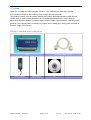
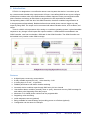
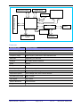
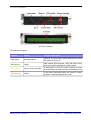
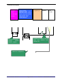
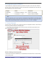
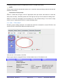
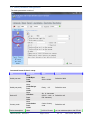
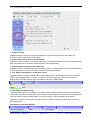
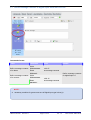
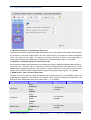
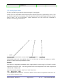
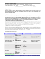
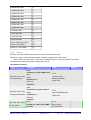
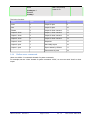
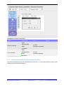
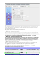
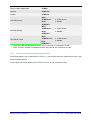
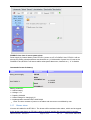
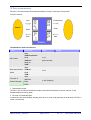
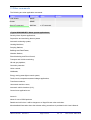
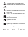
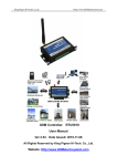
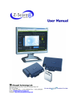
GSM Controller
RTU5011
User Manual
Ver 1.2 Date Issued: 2009-02-28
All Rights Reserved by King Pigeon Hi-Tech. Co., Ltd.
King Pigeon Hi-Tech.Co.,Ltd.
Http://www.GSMalarmsystem.com
CONTENTS
I
Preface ...................................................................................................................... .
3
RTU5011 standard pack components.............................................................................................. 3
II
Introduction................................................................................................................ .
4
Features .......................................................................................................................................... 4
Parameter........................................................................................................................................ 5
RTU5011 interface........................................................................................................................... 6
III
Configuration guide of RTU5011 ................................................................................
8
3.1 Access setup mode ................................................................................................................. 8
3.2 Add
“CS number”.................................................................................................................. 9
3.3 Basic parameter configuration............................................................................................... 10
3.4 parameters for alarm ............................................................................................................. 13
3.5 Digital input types .................................................................................................................. 15
3.6 Output types .......................................................................................................................... 16
3.7 Define message contents of digital input alarm and recover ................................................. 18
3.8 Digidal inputs alarm parameters............................................................................................ 19
3.9 Analog input alarm ................................................................................................................ 20
3.10 Define message contents of AD input alarm and recover...................................................... 23
3.11 Setting AD sensor name........................................................................................................ 24
3.12 Interlock outputs .................................................................................................................... 25
3.13 Timers ................................................................................................................................... 26
3.14 Define users commands........................................................................................................ 27
3.15 Internal temperature sensor (optional function) ..................................................................... 28
3.16 Power cut off alarm (optional function) .................................................................................. 30
3.17 Buzzer alarm ......................................................................................................................... 31
IV
V
Data transmission..................................................................................................... 33
Other commands ..................................................................................................... .
34
GSM Controller RTU5011
Page 2 of 36
Ver 1.2
Date Issued: 2009-02-28
I Preface
Thank you for using the GSM Controller RTU5011. You will know well about the functions
and operation methods of this product quickly through this User’s Manual.
This product is mainly used for remote alarming and control application based on GSM network.
Please use it according to the parameters and technical specifications in the User’s Manual.
Meanwhile, the Notes shall be considered for the usage of radio-control products, especially GSM
products. Our Company bears no liability for property loss or bodily injury arising from abnormal or
incorrect usage of this product.
RTU5011 standard pack components
Host
12V AC adapter
GSM Controller RTU5011
Serial prot cable RS232
GSM antenna
Page 3 of 36
CD
Ver 1.2
Date Issued: 2009-02-28
II Introduction
RTU5011 is designed as a cost effective remote control system alert device. It monitors up to 8
dry contacts and 8 drivable relay outputs and 4 AD input. User-defined SMS is sent to pre-configure
mobile phone numbers when a pre-defined alarm condition happens.These pre-configured mobile
phone numbers can belong to technicians or engineers who are responsible in handling
corresponding alarms. With the aid of this GSM Controller, the alarm condition brings attention to
in-charge personnel immediately. Besides it allows those mobile phone users to trigger any relay
output by using SMS. The output can be connected with alarm indication device, such as alarm, and
others.
There is a built-in microprocessor chip running on a real-time operating system. It gives immediate
response to any change in both inputs and outputs condition. A GSM modem is embedded in the
GSM Controller, user has to subscribe a SIM card for the GSM Controller. The GSM Controller can
be installed in any location under GSM coverage.
Features
z
z
z
z
z
z
z
z
z
z
z
8 digital inputs,connect dry contact device
8 relay drivable outputs(12V-24V),drive electricity <0.2A
4 Analog input, 0-53 mA,10 precision
Reliable performance with built-in double watchdog
Automatic device condition report through SMS every 24 hour interval
User-defined alarm condition (normally close or open), alarm and recovery SMS message for
each alarm point;Supporting drive relay output
Maximum of 10 mobile phone numbers can be programmable
Supporting voice monitoring
Inside temperture sensor (optional)
Being available for internal battery and providing power cut off alarm (optional)
Configuration can be done via COM port.
GSM Controller RTU5011
Page 4 of 36
Ver 1.2
Date Issued: 2009-02-28
Relay drive output
Digital inputs
GSM Engine
RS-232 Interface
Watchdog
NXP
Industrial MCU
Power
management
Battery
Audio
management
Internal temperature
sensor
DC Input
Parameter
Parameter item
Reference scope
DC Power supply
6-28V DC (Standard adapter: DC 12V/1.5A)
Power consumption
12V input
Frequency range
Dual-frequency 900/1800 or 900/1800/850/1900
SIM Card
Supporting 3V SIM Card
Antenna
50 Ω SMA Antenna interface
Serial
RS232
Temperature range
-10-+70 °C
Humidity range
Relative humidity 95%
Output drive voltage
Equal to input DC voltage
Output drive power
Drive voltage ≤35V, drive current ≤200mA
On state input current
Max. 0.33mA
Input signal
Dry contact
Exterior dimension
130×80×25mm
Weight
300 g
GSM Controller RTU5011
Max. 50mA/Average 50mA
Page 5 of 36
Ver 1.2
Date Issued: 2009-02-28
RTU5011 interface
RTU5011 interface
LED indicator discription
Indicator
Status
Indication discription
PWR (Red)
Normally light on
Indicator for power supply, which will be light on when
the system is power on
NET (Green)
Flicker
SMS module signal indicator, which will flicker slowly
after the system is registered in GSM network
SRV (Yellow)
Light on during handling
It will be light on when the system receives or sends
short messages and light off when the handling is over
ACT (Orange)
Flicker
It will flicker periodically when the system is under
operation, and the interval time is 6 sec
GSM Controller RTU5011
Page 6 of 36
Ver 1.2
Date Issued: 2009-02-28
Connector Description
4 Analog
inputs,
0-53mA,10p
recision
8 relay drivable
outputs(12V-24V),drive
electricity <0.2A
Output drive relay voltage
Equal to input DC voltage
Output power: Drive
voltage ≤35V, drive
current ≤200mA
analog
device
8 digital input
RS232
DC
9-28V
relay
Connect I/O device such as
relay, door detector, PIR
detector etc.
Connect transmitter ,
accept
0-53ma
electric signals
RS232 for configuration
GSM Controller RTU5011
Page 7 of 36
Ver 1.2
Date Issued: 2009-02-28
III Configuration guide of RTU5011
A special parameter configuration software is provided for this product, at the same time, RTU5011
provides a group of SMS commands for the user's remote product configuration and control with sms.
See the following for sms command formats:
Category
Format
Description
Configuration
% command + parameter + < CR >
Return to OK or ERROR
Inquiry
% command + ? + < CR >
Return to Result or ERROR
Note
With the commands, the user can execute his configuration through RS232 or sms without using
the configuration software. But the point is that when the input command is made through RS232,
the “%” has to be input ahead, while if it is send vis sms, no “%” or “< CR >” is needed.
3.1 Access setup mode
Connect RTU5011 with RS232 of the computer and open the configuration software, make RTU5011
access setup mode according to the following figure.
Note: Please choose the serial port No. and rate correctly, the default communication rate is
9600, default password is “000000”
Definition: Working mode and setup mode
In setup mode,all functions is disabled,only to set parameters.after set,the RTU5011 must be restart
to enter working mode.
GSM Controller RTU5011
Page 8 of 36
Ver 1.2
Date Issued: 2009-02-28
In working mode,all functions is enabled,the RTU5011 can alarm and control.
NOTE
Access setup mode,the simcard and antenna is no need,but access wording mode,the simcard and
antenna is necessary.
How to know current mode:
Method 1: Check the ACT light, if the ACT light flickers twice per second, that means it is under the
setup mode currently; The flicker period of the ACT light can be up to 6 sec under the working mode
Method 2: Check the information from the serial port, if the character string of “dtu come in setup
mode” occurs, it means that RTU5011 is under the setup mode.
3.2 Add “CS number”
RTU5011 Under working mode,the “CS number”can send sms commands to control RTU5011 and
receive RTU5011 sms(include alarm sms,report sms etc).
User can set 10 CS numbers, CS0-CS9
When inputs states is changed,RTU5011 will send alarm sms to CS numbers in turn.
Item
commands
value
Remark
n: 0 to 9
phone: handphone
number or null
CS number can control
RTU5011 vis sms and
receive alarm sms
Write number
%CS<n><phone>
Read the one of number
CS number
%CS<n>?
Read all number
%CS?
Del number
%CS<n>
GSM Controller RTU5011
Page 9 of 36
Ver 1.2
Date Issued: 2009-02-28
3.3 Basic parameter configuration
The basic parameters consist of:
Command format for basic setup:
Item
Serial port rate
Serial port parity
Device ID
Country code
Device description
commands
Write
%UB<Bps>
Read
%UB?
Write
%UP<Parity>
Read
%UP?
Write
%ID<Str>
Read
%ID?
Write
%CC<Code>
Read
%CC?
Write
GSM Controller RTU5011
value
Remark
Bps:
2400-115200
Default is 9600
Parity: 0-5
Default is none
Str: 8 characters
(ASCII code or Default is null
null character)
Code: Country
code
Default is null
UCS:UCS code
you can add description with RTU50
Page 10 of 36
Ver 1.2
Date Issued: 2009-02-28
%DESC<Ucs>
of description
Read
%DESC?
Write
%DAS<En>
11(such as install position,user
information),the description will show
in sms which RTU5011 send to you
En: 0 or 1
0: disable
1: enable
Daily report at 10 am
Write
Need alarming or not %SIGNALA<En>
when GSM signal
Read
low
%SIGNALA?
En: 0 or 1
0: disable
1: enable
GSM signal normal range is 18-30,
RTU5011 will send alarm sms to
user when the value of GSM signal
below 9
Write
Update the device’s %PRTCS<En>
clock by cs number
Read
when power up
%PRTCS?
En: 0 or 1
0: disable
1: enable
Enable this function,RTU5011 will
send sms to CS0 number to request
update clock when power up,CS0
number can send any sms to
RTU5011 to complete upate clock
En: 0 or 1
0: disable
1: enable
Enable this function,RTU5011 would
reply sms if user have sent correct
sms commands.
En: 0 or 1
0: disable
1: enable
Enable this function,RTU5011 would
reply sms if user have sent incorrect
sms commands.
Need daily report or
not
Need reply sms for
remote successful
sms commands
Need reply sms for
remote incorrect
sms commands
Read
%DAS?
Write
%RPLSUC<En>
Read
%RPLSUC?
Write
%RPLERR<En>
Read
%RPLERR?
1. Device ID
The device ID is a 8-byte ASCII characters which will be showed in the short-message received by
CS, for example:
From: +8613570810254
DTU startup
Equipment Id:12345678
Time: 9:58
Signal value: 27
Power supply: Normal
Computer temperature:30.5
Description: Machine Room
A1, Floor 4, Building 3
The device ID can be used during the data transmission process. See RTU5011 Data
Transmission manual for the detailed data formats.
2. Alarm for GSM signal low
GSM signal normal range is 18-30, RTU5011 will send alarm sms to user when RTU5011’s GSM
GSM Controller RTU5011
Page 11 of 36
Ver 1.2
Date Issued: 2009-02-28
signal value below 9
The possible reasons of RTU5011 GSM sighal low is:
·RTU5011’s GSM antenna is covered with metal box.
·RTU5011 is interfered by other radio device.
3. Update clock
The function of update clock is keeping the time of RTU5011’s os(operation system) identical with
current time.after update clock,RTU5011 can execute daily report, timing arm or disarm,timing output
at correct time.User can send any sms to RTU5011 to complete update clock when RTU5011 power
up.
4. Device description
you can add description with RTU5011 (such as install position , user information),the description will
show in sms which RTU5011 send to you
From: +8613480165874
DTU startup
Equipment Id:1234
Time: 9:58
Signal value: 27
Power supply: Normal
Computer temperature: 30.5
Description: Machine Room
A1, Floor 4, Building 3
5. Daily report
When the daily report function is used, RTU5011 will send a report sms to all CS numbers at 10:00
every morning for reporting current states, through which the user can make sure the normal
operation of RTU5011.
GSM Controller RTU5011
Page 12 of 36
Ver 1.2
Date Issued: 2009-02-28
3.4 parameters for alarm
1. Ring when alert
enable this option, RTU5011 will give CS number a ring then send sms when input alarm,but
RTU5011 have not automatic voice system
2. Auto answer call for service phonenumber
enable this option, RTU5011 can auto answer call for service phonenumber, if MIC and speaker have
been connected,user can monitor voice and make voice broadcasting.
3. Auto add basic description with alert sms
enable this option, the description (such as install position , user information) that have been defined
by user will show in sms which RTU5011 send to service phonenumber.
4. Use digital input channel 1 as defence control
enable this option, RTU5011 will be in arm mode if digital input 1 is opened and RTU5011 will be in
disarm mode if digital input 1 is closed, so user can connect a button to switch mode for arm or
disarm service number also can send command to set arm or disarm mode:
Item
commands
arm
%BF
disarm
%CF
value
5. Arm delay and disarm delay
User can define a time for Arm delay, in the time RTU5011 will ignore alarm when input is triggered,
In this way, user have a enough time to set RTU5011 in arm mode when user leave the monitor area.
User can define a time for disarm delay, in the time RTU5011 will ignore alarm when input is
triggered, In this way, user have a enough time to set RTU5011 in disarm mode when user go into
the monitor area.
Commands for alarm parameters:
Item
Continuous times for
GSM Controller RTU5011
commands
value
Write
n: 1-255 (times)
Page 13 of 36
Remark
Ver 1.2
Date Issued: 2009-02-28
alarm
%IOAT<n>
Read
%IOAT?
Write
IOAS time
%IOAS<n>
n: 0-255 (minute)
0 : disable
Read
%IOAS?
Write
IOLS time
%IOLS<n>
n: 0-255 (minute)
0 : disable
Read
%IOLS?
Write
Need or not ring when
alarm
En: 0,1
0: disable
1: enable
%ARING<En>
Read
%ARING?
Write
Need or not answer for
service number
En: 0,1
0: disable
1: enable
%ASC<En>
Read
%ASC?
Write
Need or not Show
description in sms
En: 0,1
0: disable
1: enable
%AWB<En>
Read
%AWB?
Need or not use input 1
as switch to arm or
disarm
Write
En: 0,1
0: disable
1: enable
%L1DEF<En>
Read
%L1DEF?
Write
Disarm delay
%INDLY<n>
n: 0-255 (second)
0: disable
Read
%INDLY?
Write
Arm delay
%OUTDLY<n>
Read
n: 0-255 (second)
0: disable
%INDLY?
GSM Controller RTU5011
Page 14 of 36
Ver 1.2
Date Issued: 2009-02-28
3.5 Digital input types
RTU5011 provide 8 digital inputs,input signals can be divided into two types, EDGE_IN (edge
triggering) and LEVEL_IN (state triggering).
0
Forbidden
1
Alarm when open contact (EDGE_IN)
2
Alarm for open contact (LEVEL_IN)
3
Alarm when closed contact(EDGE_IN)
5
Alarm for close contact(LEVEL_IN)
Select the type whether to alarm on open/close contact.
There are nuances between EDGE_IN input and LEVEL_IN input.
LEVEL_IN
EDGE_IN
Trigger alarm
√
√
Recover alarm
√
×
Repeat alarm in triggering status
√
×
Interlock output when alarm
√
√
Interlock output when recovered
√
×
Note: The alarm and recover sms contents corresponding to different inputs can be defined by
the user, see the following sections for the operation method.
“Urgent” option:
RTU5011 provide a “Urgent” option for each digital input, If checked, in any case, the digital input will
execute alarm action(send alarm sms, interlock etc) when it is triggered, even RTU5011 is in disarm
mode.
GSM Controller RTU5011
Page 15 of 36
Ver 1.2
Date Issued: 2009-02-28
Command format for input and output:
Item
commands
Write
%IOTP<Type str>
Type of input and
output
Read
%IOTP?
Read outputs
status
%IOOS
Read inputs status
%IOIS
value
Remark
Typestr:
nnnnnnnnxxxxxxxx
(nnnnnnnn:
eight-digit input type
string
xxxxxxxx:
eight-digit output
type string)
Default inputs are all edge_in
Default outputs are OC output
Write
%IOIP<nnnnnnnn >
Disable inputs
alarm
Read
nnnnnnnn: one-digit
or multidigit numeral
%IOIP?
Write
%IOIC<nnnnnnnn >
Enable inputs
alarm
Read
nnnnnnnn: one-digit
or multidigit numeral
%IOIC?
For example,disable input1,
command is %IOIP1,disable
input0-3,command is %IOIP0123
For example,enable input1,
command is %IOIC1,enable
input0-3,command is %IOIC0123
3.6 Output types
0
diable
8 relay drivable outputs,drive electricity <0.2A Output
1
relay drivable output
drive relay voltage Equal to input DC voltage Output
power: Drive voltage ≤35V, drive current ≤200mA
Choose this type,outputs can connect howl,In arm mode,if
2
HOWL
3
SNAPSHOOT
alarm,the howl will be screaming for one minute
Commands format for howl outputs:
Item
commands
value
Remark
En: 0-1
howl output
%BUZEN<En>
0: disable
1: enable
Commands format for control outputs:
GSM Controller RTU5011
Page 16 of 36
Ver 1.2
Date Issued: 2009-02-28
Item
Read outputs status
commands
value
Remark
%IOOS
Write
Open output contact
%IOOL<nnnnnnnn>
nnnnnnnn: one-digit
Read
or multidigit numeral
%IOOL?
For example,open all outputs
contact
command is IOOL01234567
Write
Output 1s pulse
%IOOP<nnnnnnnn>
nnnnnnnn: one-digit
Drive output open -> close ->
Read
or multidigit numeral
open ,drive time is 1.5s
%IOOP?
Write
Close output contact
%IOOH<nnnnnnnn>
Drive one or several of outputs
Read
close
%IOOH?
Remember outputs
Write
status
%IOOR<En>
En: 0-1
0: disable
1: enable
Note: Remember outputs status
RTU5011’s outputs default status is open,it is possiable closed during working. after restart,the
outputs will be reset,status is open. If checked,outputs can recover the status that before restart.
GSM Controller RTU5011
Page 17 of 36
Ver 1.2
Date Issued: 2009-02-28
3.7 Define message contents of digital input alarm and recover
Commands format
Item
commands
value
Remark
Write
Define message contents
of on alarm
%S<nn><str>
Read
n:00-07
str:message contents
%S<nn>?
Define message contents
of on recover
Define message contents
for digital input 0-7
Write
%S<nn><str>
Read
n:08-15
str:message contents
%S<nn>?
NOTE:
A necessary condition for get recover sms is Digital input type is level_in
GSM Controller RTU5011
Page 18 of 36
Ver 1.2
Date Issued: 2009-02-28
3.8 Digidal inputs alarm parameters
1. IOLS time :timespan of resend input alarm sms
After executed a alarm action(send alarm sms,interlock etc.) when digital inputs detect alarm signal,if
the duration of the alarm signal overrun the IOLS time,RTU5011 will execute a alarm action(send
alarm sms, interlock etc.) again. The purpose of setting IOLS time is alarm to user repeatedly at
regular intervals during the digital input is triggered by a continues alarm signal. “0” is disable
2. IOAS time : minimum timespan of twice alarm sms
After executed a alarm action(send alarm sms,interlock etc.)when digital inputs detect alarm signal, in
the IOAS time , RTU5011 will not execute any alarm action(send alarm sms,interlock etc.) even
digital inputs is triggered frequently. The purpose of setting IOAS time is user will not receive many
alarm sms in the time during the digital input is triggered by frequent alarm signals. “0” is disable
3. DINDLY time : time of ensure input alarm
RTU5011 will not execute any alarm action(send alarm sms,interlock etc.) in the DINDLY time even
digital inputs is triggered, if the duration of the alarm signal overrun the DINDLY time,RTU5011 will
execute a alarm action(send alarm sms, interlock etc.) “0” is disable
Item
commands
value
Remark
Write
IOLS time
%IOLS<n>
n: 0-255 (min)
0: diable
Read
%IOLS?
Write
IOAS time
%IOAS<n>
n: 0-255 (min)
0: diable
Read
%IOAS?
Write
DINDLY time
n: 0-255 (sed)
0: diable
%DINDLY<n>
Read
GSM Controller RTU5011
Page 19 of 36
Ver 1.2
Date Issued: 2009-02-28
%DINDLY?
3.9 Analog input alarm
RTU5011 provide 4 input channels that can accept 0-53 ma signals.
Analog input is a measurable electrical signal with a defined range that is generated by sensor. User
can preset a high and a low level for every AD input,if the input electriacl signal is above the high
level or below the low leve,RTU5011 should alarm.user can also send sms command to
RTU5011 to remote get current level.
NOTE
“Current” value = input electric current value / (“scale” value / 62) – “base” value
Scale default value is 62, base default value is 0, so the scale and base are assigned to default
value,the ”current” value is input electric current.
Example:
User connect a temperature transmitter which output electric current range is 4-20 ma for monitor
temperature range is 0℃-50℃, user need get alarm and current temperature value when temperature
is above 40℃ or below 10℃
User can preset the values for “high”,”low”,”scale”,”base” are:
High:
40
low: 10
In this case,the function of “scale” is transform electric current value to temperature value when the
current value is showed to user.
GSM Controller RTU5011
Page 20 of 36
Ver 1.2
Date Issued: 2009-02-28
Algorithm for “scale” and ”base”:
First, need to get the value that a 1am for temperature. (50-0)/(20-4)=3.125
“scale” value is 62/3.125, get 19.84
”base” value is 4*3.125, get
12.5
“Urgent” option:
RTU5011 provide a “Urgent” option for each AD input, If checked, in any case, the RTU5011 will
execute alarm action(send alarm sms, interlock etc) when the AD input is over normal range, even
RTU5011 is in disarm mode.
1. AINAS time : minimum timespan of twice alarm sms
After executed a alarm action(send alarm sms,interlock etc.)when AD inputs over normal range, in
the AINAS time RTU5011 will not execute any alarm action(send alarm sms,interlock etc.) even AD
inputs is over normal range frequently. The purpose of setting AINAS time is user will not receive
many alarm sms in the time during the AD input is over normal range frequently. “0” is disable
2. AINLS time :timespan of resend input alarm sms
After executed a alarm action(send alarm sms,interlock etc.) when AD inputs over normal range, if
the duration of the alarm signal overrun the AINLS time,RTU5011 will execute a alarm action(send
alarm sms, interlock etc.) again. The purpose of setting AINLS time is alarm to user repeatedly at
regular intervals during the AD input is in state of over normal range. “0” is disable
3. AINDLY time : time of ensure input alarm
RTU5011 will not execute any alarm action(send alarm sms,interlock etc.) in the AINDLY time even
AD inputs is over normal range, if the duration of the alarm signal overrun the AINDLY time,RTU5011
will execute a alarm action(send alarm sms, interlock etc.). “0” is disable
Commands fomat for AD input
Item
commands
value
Remark
n: 0-3
val: 0-255
Alarm when input signal
is below the value
n: 0-3
val: 0-255
Alarm when input signal
is above the value
Write
Preset low value for AD
input at one channel
%AIN<n>L<val>
Read
%AIN<n>L?
Write
Preset high value for AD
input at one channel
%AIN<n>H<val>
Read
%AIN<n>?
Write
Scale value
%AIN<n>SC<val>
Read
n: 0-3
val: 0-255
%AIN<n>SC?
Write
Base value
%AIN<n>ZE<val>
Read
n: 0-3
val: 0-255
%AIN<n>ZE?
Query preset rang for AD
GSM Controller RTU5011
%AIN<n>R
n: 0-3
Page 21 of 36
Ver 1.2
Date Issued: 2009-02-28
input at one channel
Query current value for
AD input at one channel
%AIN<n>C
Query current value for
for AD input
%ADS
Enable AD input alarm
Disable AD input alarm
n: 0-3
%AINON<xxxx>
xxxx:
one-digit or multidigit
numeral
%AINOFF<xxxx>
xxxx:
one-digit or multidigit
numeral
Write
AINLS time
%AINLS<n>
n: 0-255 (min)
0: diable
Read
%AINLS?
Write
AINAS time
%AINAS<n>
n: 0-255 (min)
0: diable
Read
%AINAS?
Write
AINDLY time
%AINDLY<n>
n: 0-255 (sed)
Read
0: diable
% AINDLY?
Note: The alarm and recover sms contents corresponding to different inputs can be defined by
the user, see the following sections for the operation method.
Examples configured by commands:
%AIN0L20 //preset low value at Channel 0
OK
%AIN0H30 // preset high value at Channel 0
OK
%AIN0R
//query value range at Channel 0
20-30mA
OK
%AIN0C
//query current value at Channel 0
28mA
OK
GSM Controller RTU5011
Page 22 of 36
Ver 1.2
Date Issued: 2009-02-28
3.10
Define message contents of AD input alarm and recover
Commands fomat for Define message contents of AD input alarm and recover
Item
commands
value
Remark
Write
Define message contents
of on alarm
%S<nn><str>
Read
n:16-19
str:message contents
%S<nn>?
Define message contents
for AD input 0-3
Write
Define message contents
of on recover
%S<nn><str>
Read
n:20-23
str:message contents
%S<nn>?
GSM Controller RTU5011
Page 23 of 36
Ver 1.2
Date Issued: 2009-02-28
3.11
Setting AD sensor name
User can define a name for each AD channel,this name will add in the sms automatically that
RTU5011 send the AD value to users
For example,set the AD input 0 channel name is “temperature”,the sms is
From:+8613570810254
Temperature cuttent value :21.33
AD input 1 cuttent value:60
AD input 2 cuttent value:0
AD input 3 cuttent value:0
Commands fomat for Setting AD sensor name
Item
commands
value
Remark
Write
Define AD sensor name
%A<nn><str>
Read
n:00-03
str:sensor name
%A<nn>?
GSM Controller RTU5011
Page 24 of 36
Ver 1.2
Date Issued: 2009-02-28
3.12
Interlock outputs
RTU5011’s outputs can be interlocked under some internal triggering conditions, which are:
1. Digital inputs alarm
2. Power failure alarm
3. Internal temperature sensor alarm
4. AD inputs alarm
5. Dialing in by CS number
Output0-output3 support interlock, user can configure the relationship of one output with another input
condition easily with the configuration software.
Commands fomat for output interlock:
Item
commands
value
Remark
Write
nnnn:
output 0-3 channel action on
alarm by “alarm source”
xxxx:
output 0-3 channel action on
recover by “alarm source”
output 0-3 channel
automatically close or
open when alarm or
recover
%IOOC<nnnnxxxx>
Action of output
Read
%IOOC?
Write
Alarm source for %IOOA<n><index>
output interlock
Read
%IOOA?
n:0-3
Index: the index of “Alarm
source”
Alarm soure include digital input alarm,AD input alarm,power cut off alarm etc.
Alarm source
GSM Controller RTU5011
Index
Page 25 of 36
Ver 1.2
Date Issued: 2009-02-28
0 digital input alert
0
1 digital input alert
1
2 digital input alert
2
3 digital input alert
3
4 digital input alert
4
5 digital input alert
5
6 digital input alert
6
7 digital input alert
7
0 AD input alert
8
1 AD input alert
9
2 AD input alert
10
3 AD input alert
11
Interior temperature alert
12
Power cut off alarm
13
Call in by “CS number”
14
3.13
Timers
RTU5011 can automatically execute actions at the time that set by user.
RTU5011’s timers include 6 system timers, 4 system timespan and 2 day timers
NOTE: before use the timers , user have to update RTU5011’s clock, the method of update
clock please see “Basic parameter configuration”above
Commands for timers:
Item
commands
value
Remark
Write
Set time and action
for System timers
%mtimer<n>,<HH>,<MM>,<acti
on>
Read
%mtimer<n>?
Read all
%mtimer?
n:0-5
HH:0-24 (hour)
MM:0-60 (minute)
action:0-18
Write
%mspan<n>,<span>,<action>
Set time and action
for System timerspan
Set time and action
for day timers
Read
%mspan<n>?
Read all
%mspan?
Write
%mday<n>,<day>,<HH>,<MM>,
<action>
GSM Controller RTU5011
Page 26 of 36
n:0-3
span:0-65535(minute)
action:0-18
n:0-5
day:0-6 (day)
HH:0-24 (hour)
Ver 1.2
Date Issued: 2009-02-28
Read
%mday<n>?
Read all
%mday?
MM:0-60 (minute)
action:0-18
The index of actiom:
Action
Index
Action
Index
none
0
Output 2 open
9
Arm
1
Output 3 open
10
Disarm
2
Output 0 close 1second
11
Output 0 close
3
Output 1 close 1second
12
Output 1 close
4
Output 2 close 1second
13
Output 2 close
5
Output 3 close 1second
14
Output 3 close
6
Snapshot
15
Output 0 open
7
Send daily report
16
Output 1 open
8
Export status by RS232
17
Trans status by sms
18
3.14
Define users commands
Users can define 10 commands instead of system commands.
For example,user set “close” instead of system command “IOOH”, so user can send “close” to close
output
GSM Controller RTU5011
Page 27 of 36
Ver 1.2
Date Issued: 2009-02-28
Commands for define commands
Item
commands
value
Remark
Write
System command
%Y<nn><str>
Read
n:00-09
str:system command
% Y<nn>?
Write
User command
% U<nn><str>
Read
n:00-09
str:define command
% U<nn>?
3.15
Internal temperature sensor (optional function)
The internal temperature senor can be selected for RTU5011. If your product does not support this
function, see the next section directly.
GSM Controller RTU5011
Page 28 of 36
Ver 1.2
Date Issued: 2009-02-28
User can preset a high and a low temperature value for temperature sensor, if temperature is over
normal range, RTU5011 should alarm.user can also send sms command to RTU5011 to remote
get current temperature value.
User can set “Adjust” value to calibrating temperature value
1. TMPAS time :timespan of twice alarm
After executed a alarm action(send alarm sms,interlock etc.)when temperature over normal range,
RTU5011 will not execute any alarm action(send alarm sms,interlock etc.) in the TMPAS time even
temperature over normal range frequently. The purpose of setting TMPAS time is user will not receive
many alarm sms in the time during temperature over normal range frequently. “0” is disable
2. TMPRS time : timespan of resend alarm sms
After executed a alarm action(send alarm sms,interlock etc.) when temperature over normal range,if
the duration of the alarm signal overrun theTMPRS time,RTU5011 will execut a alarm action(send
alarm sms, interlock etc.) again. The purpose of setting TMPRS time is alarm to user repeatedly at
regular intervals during temperature is in state of over normal range. “0” is disable
3. TMPDLY time : time of ensure alarm
RTU5011 will not execute any alarm action(send alarm sms,interlock etc.) in the TMPDLY time
even digital inputs is triggered, if the duration of the alarm signal overrun the TMPDLY
time,RTU5011 will execut a alarm action(send alarm sms, interlock etc.)
“0” is disable
Commands format for internal temperature sensor:
Item
commands
Remark
Preset lower limit for temperature range
%TMPL
Min. lower limit temperature: -127℃
Preset upper limit for temperature range
%TMPH
Max. upper limit temperature: +127℃
Query temperature range
%TMPR
GSM Controller RTU5011
Page 29 of 36
Ver 1.2
Date Issued: 2009-02-28
Query current temperature
%TMPC
Disable
%TMPOFF
Enable
%TMPON
Set TMPRS time
Set TMPAS time
Set TMPDLY time
Write
%TMPRS<n>
Read
%TMPRS?
Write
%TMPAS<n>
Read
%TMPAS?
Write
%TMPDLY<n>
n: 0-255 minute
0: disable
n: 0-255 minute
0: disable
n: 0-255 second
0: disable
Read
%TMPDLY?
Note: The TMP100 temperature sensor from TI Company.It is installed on PCB.
Note: The sms contents of temperature alarm and recover are not defined by user
3.16
Power cut off alarm (optional function)
The internal battery can be selected for RTU5011. If your product does not support this function, see
the next section directly.
Power supply by internal battery when RTU5011 power cut off, and alarm to user
GSM Controller RTU5011
Page 30 of 36
Ver 1.2
Date Issued: 2009-02-28
POWDLY time: time of ensure power alarm
Power supply by internal battery when RTU5011 power cut off, in POWDLY time, RTU5011 will not
execute any alarm action(send alarm sms,interlock etc.), if the duration of power cut off overrun the
POWPDLY time,RTU5011 will execut alarm actions(send alarm sms, interlock etc.) “0” is disable
Commands format for battery:
Item
commands
Query power supply
Remark
%POW
Write
Set POWDLY
%POWDLY<n>
n: 0-255S
Read
0: disable
%POWDLY?
Battery parameter:
z Lithium battery
z Voltage: 3.7V
z Capacity: 900mAh
z Limited voltage for charging 4.2V
z Implementation standard GB/T 18287-2000
Note: The sms contents of power cut off alarm and recover are not defined by user
3.17
Buzzer alarm
A buzzer is installed in the RTU5011. The buzzer will be activated when alarm, which can be stopped
by the buzzer reset button on RTU5011 panel, or through sending the command with CS number
GSM Controller RTU5011
Page 31 of 36
Ver 1.2
Date Issued: 2009-02-28
remotely.
Commands for buzzer:
Item
commands
Stop buzzer
%BUZCLR
Start buzzer
%BUZSET
Enable or disable
buzzer
%BUZEN<En>
GSM Controller RTU5011
value
Remark
En: 0 or 1
0: disable
1: enable
Page 32 of 36
Ver 1.2
Date Issued: 2009-02-28
IV Data transmission
RTU5011 can also provide RS23 data transmission function. See Data Transmission
Function manual.
Network
receiving
data
Network
sending
RS23
Serial
port
sending
Device
Serial port
receiving
data
Packet+data
GSM
data
RTU5011
Commands for data transmission:
Item
commands
value
Remark
Write
%SR<n><phone>
SR number
Read
%SR<n>?
n:0-9
phone:number
Read all
%SR?
Write
Data transmission
%TM<n>
mode
Read
%TM?
n:0-5
Write
The time of
%OT<n>
Packet idle span
Read
%OT?
n:120-5000(ms)
1. Transmission mode:
RTU5011 can provide 5 transmission modes, see Data Transmission Function manual. for the
detailed difference among them.
2. The time of Packet idle span
It determines the data package sending time when no new serial port data is received by RTU5011
within a certain time
GSM Controller RTU5011
Page 33 of 36
Ver 1.2
Date Issued: 2009-02-28
V Other commands
The following are other applicable commands:
Item
commands
Load default
%ATF
Restart
%RST
Send AT command
%AT<n>
value
Remark
n:AT command
★Typical GSM SMS RTU Alarm system applications:
Security Alarm System applications;
Supervision and monitoring alarm systems
Automatic monitoring system;
Vending Machines;
Pumping Stations;
Buildings and Real Estate;
Weather Stations;
River Monitoring and Flood Control;
Transport and Vehicle monitoring;
Oil and gas pipelines;
Corrosion protection
Valve controls;
Wellheads;
Energy saving,street lights control system;
Tanks, levels, temperatures,water leakage applications;
Transformer stations;
Unmanned machine rooms;
Automatic vehicle locations (AVL);
Control room application.etc.
Annex A:
Notes for use of GSM products
Read these brief rules. It will be dangerous or illegal if these rules are broken.
More detailed information about the relevant safety precautions is provided in this User’s Manual.
GSM Controller RTU5011
Page 34 of 36
Ver 1.2
Date Issued: 2009-02-28
Safety startup
The temporary Power Off function of the startup module shall be considered if the
mobile phone is not allowed or the use of it will cause interference or dangerousness.
Interference
All GSM signals of radio modules may be interfered and therefore the performance of
positioning module will be interfered.
Power off while refueling
Use of positioning module in petrol filling station is not allowed. The temporary
Power Off function of the product shall be considered if it is near fuels or chemicals
and the module shall be under Power Off state.
Power Off at blasting site
All relevant rules shall be abided by. No use of positioning module is allowed at
blasting site, and it shall be under temporary Power Off state.
Correct usage
Please install this product correctly according to the text. No cover of module is
allowed if it is not necessary due to signal blind.
Supporting qualified maintenance service
Only qualified maintainers are allowed for the installation or maintenance of this
positioning module.
Waterproofness
Your positioning module is not provided with waterproof performance. Please put it at
a dry position and keep it dry.
The end!
Thanks for you use our GSM Alarm System
GSM Controller RTU5011
Page 35 of 36
Ver 1.2
Date Issued: 2009-02-28
Warranty Card
Model
Product ID
Date of Purchase
Date of Production
Maintenance Record
Dealer
GSM Controller RTU5011
Page 36 of 36
Ver 1.2
Date Issued: 2009-02-28