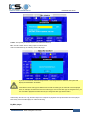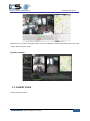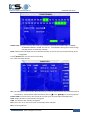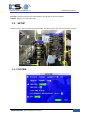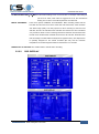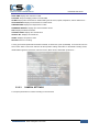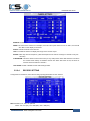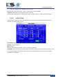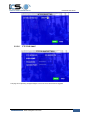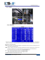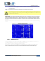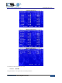
1
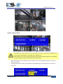
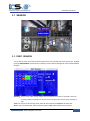
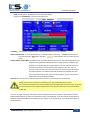
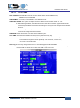
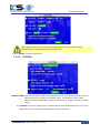
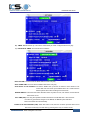
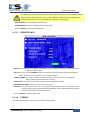
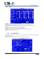
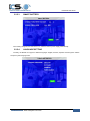
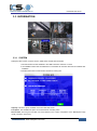
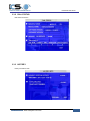
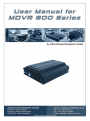
ICS-MDVR-800 Series NOTICE The information in this manual was current when published. The manufacturer reserves the right to revise and improve its products. All specifications are therefore subject to change without any notice. The purpose of this manual is to aid the user for the operation of ICS-MDVR-800 Series. The user should have a basic understanding of computer operation and a basic knowledge of making electrical connections and configurations. Copyright Under copyright laws, the content of this manual may not be copied, photocopied, reproduced, translated or reduced to any electronic medium or machine- readable form, in whole or in part, without prior written consent of Initial Concept Solutions Limited Copyright 2012-2014 More Information www.transport-cctv.com 1 ICS-MDVR-800 Series Table of Content 1 PRODUCTION CHRACTERISTICS AND OVERVIEW 4 1.1 PRODUCT OVERVIEW 1.2 REMOTE CONTROL 1.3 GUI (GRAPHIC USER INTERFACE) TREE 4 5 8 2 SYSTEM START UP 8 3 GUI CONFIGURATION 10 3.1 SEARCH 3.1.1 REC. SEARCH 3.1.2 EVENT FILES 3.2 SETUP 3.2.1 SYSTEM 3.2.1.1 DATE/TIME 3.2.1.2 OPTIONS 3.2.1.3 REGISTER INFO 3.2.1.4 FORMAT 3.2.1.5 UPGRADE 3.2.1.6 USER SECURITY 3.2.1.7 CONFIG 3.2.1.8 USER LOG 3.2.1.9 BLACKBOX FILE (optional) 3.2.1.10 GEO-FENCING 3.2.2 RECORD 3.2.2.1 OPTION 3.2.2.2 OSD OVERLAY 3.2.2.3 CAMERA SETTINGS 3.2.2.4 RECORD SETTING 3.2.2.5 SUB-STREAM 3.2.2.6 SCHEDULE 3.2.2.7 OTHER SETTINGS 3.2.3 NETWORK 3.2.3.1 LOCAL 11 11 14 16 16 17 18 20 20 21 23 24 25 26 26 27 27 29 30 31 32 33 33 35 35 More Information www.transport-cctv.com 2 ICS-MDVR-800 Series 3.2.3.2 SERVER NETWORK 3.2.3.4 MOBILE NETWORK 3.2.3.5 FTP SETTINGS 3.2.3.6 FTP FOR SNAP 3.2.4 EVENT 3.2.4.1 SENSOR 3.2.4.2 SENSOR OUTPUT 3.2.4.3 SPEED 3.2.4.4 ACCELERATION 3.2.4.5 TEMPERATURE 3.2.4.6 CAMERA 3.2.4.7 VOLTAGE 3.2.4.8 EMERGENCY EVENT 3.2.5 PERIPHERAL 3.2.5.1 PTZ 3.2.5.2 EXT.COM SETUP 3.2.5.3 SMART BATTERY 3.2.5.4 LANGUAGE SETTING 3.3 INFORMATION 3.3.1 SYSTEM 3.3.2 DIAL STATUS 3.3.3 HISTORY 3.3.4 MODULES 3.3.5 BATTERY INFO More Information www.transport-cctv.com 36 37 39 41 42 42 43 44 45 46 46 47 47 48 49 49 50 50 51 51 52 52 53 54 3 ICS-MDVR-800 Series 1 PRODUCTION CHRACTERISTICS AND OVERVIEW 1.1 PRODUCT OVERVIEW The ICS-MDVR-800 SERIES is a middle of the range MDVR model specially designed for vehicle surveillance and remote monitoring, combined with high-speed processor and an embedded operating system. The advanced H.264 video compression/decompression, wireless transmission, and GPS location make the ICS-MDVR-800 a very powerful and perfect solution for all types of transportation vehicles. MDVR Features and Capabilities Support HDD recording UPS (Uninterrupted Power Supply-not fitted as standard, must be ordered separately) provide backup power Dual streams: one for local recording/playback and one for wireless transmission (system specific) Real-time D1 at 25 fps/30fps continuous or priority video recording and live view display. Synchronized semi-transparent GUI for GUI and live display. Mirrored recoding makes the hard disk and SD card recording at the same time with same frame, same to the MDVR when the external power is cut off (for example; in the event of a serious accident) resolution and same image quality(System Specific) Maximum 1 hour pre-recording and 30 minutes post-recording Watermarking prevents any modification within the recorded file which is part of law enforcement. Better Compression rate at H.264 (50% less than MPEG4). High-fidelity, digitally, synchronized audio (System Specific) User friendly interface in playback with associated events. Automatic display timer to resume the live display if the unit is idle for a period of time. User-selectable settings for quality and audio recording (enable/disable for each channel) External power supply for multiple devices such as cameras, sensors, relays and any other accessories (System Specific), Remote Connection Capabilities PC-Based Client software for live view, playback video, playback events associated video, and download capabilities. Support CMS (Central Management System) for remote monitoring via built-in 3G module (HSPA or EVDO), Ceiba (Playback Analysis Software) for video playback, meta-data analysis. ADS by WIFI to download the video files and event files. More Information www.transport-cctv.com 4 ICS-MDVR-800 Series 1.2 REMOTE CONTROL Numeric Input Keys Use the numbers to input Values in the system setup Screen or switch through the channels in QUAD view Navigation Arrows Use the ARROW keys to move between selections, input fields and icons. Press ENTER to select And EXIT to return and enter into the OSD screen to check the MDVR working status. The next and previous buttons are also used to increase or decrease volume when in live view or within the search screens. Each MDVR includes a remote control that allows the user to transmit commands to the recording module and used to display the on-screen control menu More Information www.transport-cctv.com 5 ICS-MDVR-800 Series Remote Control Key Functions: 1) Numeric Keypad [0-9] keys: During setup, number keys are used to input number values. In QUAD view, the user can press 1, 2, 3 and 4 to switch the full screen for each channel, and press 0 to switch to quad view. During full screen view of each camera, the user can press key to adjust contrast, luminance, color and saturation, and then press + and - to make the adjustments. Pressing will navigate through the color adjustment options. 2) Setup Menu Navigation ▲, ▼: Up, down directional keys: Move selection up and down in setup menu. ►, ◄: Left, Right directional keys: Move cursor left or right in setup menu. [ENTER] key: During setup, select and save the settings 3) Other Keys Function LOGIN/ LOCK POWER You can press LOGIN / LOCK or SETUP keys to enter the GUI setup. If password enabled, you need to input the default Admin password: 88888888. To put the MDVR into sleep mode (You can press power button, and press again to wake up Switch to the full screen of one channel and also into quad view. Brightness, contrast, colour adjustment for per channel. Use [+] [-] button to change the values. To adjust the values for each channel individually. SETUP Login GUI to setup the parameters. EXIT Return to the previous menu. STOP RECORD PAUSE/STEP ▐► PLAY ► SLOW GOTO NEXT Used to stop the recording manually. Only valid when you setup the record mode as “manual”. Used to start the recording manually. Only valid when you setup the record mode as “manual”. Freezes playback to a single frame and can advance one frame at a time. To advance the frame press Pause / Step to move frame by frame. Press EXIT to return to normal playback speed. Starts/Resumes playback from any other mode (FF, RR, Frame by Frame etc.) Reduces playback speed to 1/2, 1/4, 1/8 modes. Press PLAY to return to normal playback speed. Quick search mode when you playback the recorded file from the MDVR. Press GOTO button and input the desired time, and the select button to jump to a specific time that want to playback. Increase volume while playback (if audio is recorded). More Information www.transport-cctv.com 6 ICS-MDVR-800 Series PREV Decrease volume while playback (if audio is recorded). 4) REW Rewinds the video while playback. X2 and X 4 modes available. FWD Fast forward the video while playback. X2 and X4 mode available. CF N/A [F1] Export all the event recorded files of the day to USB by pressing the F1 key. [F2],[F3],[F4] Reserved for future use. PTZ Function Key The 800 series MDVR can support PTZ cameras using the protocol PALCO-D or PALCO-P. While the MDVR is connected the PTZ camera by RS485 signal (on the RS232/485 expand box), the following commands can control PTZ: [ZOOM IN +], [ZOOM OUT -] ZOOM IN/OUT [IRIS +], [IRIS-] Brightness control [FOCUS +], [FOCUS -] Focus control PTZ Enable the PTZ function AUTO Auto run with the PTZ pattern PRESET Preset default position RECALL Recall the position that the user have setup. BRUSH Brush the glass screen Check battery is in place for the remote control (no battery is supplied) More Information www.transport-cctv.com 7 ICS-MDVR-800 Series 1.3 GUI (GRAPHIC USER INTERFACE) TREE 2 SYSTEM START UP After connecting the MDVR to the vehicles power supply, turn on the vehicle ignition and the unit will automatically start up. Power is normally supplied to the MDVR as long as the vehicle ignition is ON. The “Display only view” of the cameras is immediately available to be viewed in quad view. Normally, the power consumption for MDVR at 12V is drawing 3A, without any accessories. More Information www.transport-cctv.com 8 ICS-MDVR-800 Series System Login for Setup The MDVR GUI is semi-transparent; you can see the live view when you make GUI configurations. The user can setup the transparency percentage from the MDVR GUI. Please make sure you lock the removable hard disk caddy before connecting the power for the MDVR, The MDVR will not be able to startup unless this caddy is locked. • When the Password is set to disable, press the “SETUP” key on the handheld controller to access the setup menu directly; • If the Password is set to enable, press LOGIN/LOCK OR ENTER key on the remote control, to access the setup menu: More Information www.transport-cctv.com 9 ICS-MDVR-800 Series DEVICE NO.: The unit ID of MDVR. The user can setup the ID for the MDVR in the menu “REGISTER INFORMATION”. After setting, the ID number will appear automatically on the login screen. (It’s the number in the bracket) PASSWORD: Enter the admin password or user password. Keyboard: Press 【Enter】to use keyboard to type device ID and password. 1)0~9, number key, press【Enter】to select the number. 2)123: Input type shift key. (Number, capital, small letter) 3)【←】delete, 【 】Exit. Default Admin password is 88888888. ADMIN PASSWORD indicates full access to MDVR. 3 GUI CONFIGURATION The following information will show all the main functions of the MDVR including SEARCH, SETUP and INFORMATION. SEARCH is for searching all the regular video files and alarm files. SETUP is for all the configurations for MDVR including recording, playback, event, network setup and INFORMATION displays the MDVR and accessory working status. You must select SAVE in the GUI menu to make all the setting valid. After the user modify the settings for the network, and recording, the MDVR system will restart automatically after the system exits to Quad view The MDVR will stop recording when using the MDVR configuration GUI. More Information www.transport-cctv.com 10 ICS-MDVR-800 Series 3.1 SEARCH 3.1.1 REC. SEARCH You are able to search all the video including alarm files by the recording time and by the file type. Highlight the option REC.SEARCH and then enter into following screen. Different background colours indicate different file types : SOURCE:Source means which storage medium the recording files are stored in. Hard disk is the main recording medium for MDVR ICS. But this model can support SD card for mirror recording as well. TYPE: The type of the file including all file, alarm file and normal file. Transparent: No video files. Green: Only normal video files, without associated alarms. Red: Alarm files have been recorded. More Information www.transport-cctv.com 11 ICS-MDVR-800 Series DATE: MDVR system will display the current date automatically. Please press【SEARCH】to enter into the below menu CHANNEL:Select the first 4 channels or the following channels when you want to playback. VIDEO FILE STATUS: GREY indicates there are no video files within the channel, normal recording file, RED means alarm files, GREEN means the file is a YELLOW means the alarm files are present and are locked.. START TIME and END TIME: The MDVR device can support the video clip function. This time schedule is for both playback locally (playback on MDVR device) and export (export to USB drive and playback on PC by MINI Player or Ceiba software). The user needs to choose the channel first, and then setup the start time and end time for the video clip. For example: if the user selects the start time at 01:20:00 and the end time at 02:20:00, then selects REPLAY, the MDVR system will playback (local playback) the video file for this period of time on this channel. During playback, the user can press the ENTER key to show the OSD information. UNLOCK: the user will need to select the channel first, and then unlock the files in a certain period. Please make active the lock files in the EVENT menu. Only EVENT files can be locked. If the video file is locked, the file cannot be deleted by the automatic HDD overwrite function. Only when you unlock the files can the HDD overwrite function work. Only the HDD format command will delete locked files. The user can export the MDVR video files to external storage device for easy playback. Simply input the START TIME and END TIME for the video from selected channels for local playback, insert the external storage device by USB port and then click EXPORT, the following screen will pop up. During backing up, the external device must not be disconnected. More Information www.transport-cctv.com 12 ICS-MDVR-800 Series TOTAL: total quantity of the files that the user selected for back up. NO.: The file number which is being copied to external drive. After successful backup, the following screen will pop up. If you do not connect an external storage device or the storage device is defective, the system will display NO EXTERNAL STORAGE. If the MDVR current video type is different from the last recorded type, the video file cannot be played back, for example, the video files were set to NSTC type, and now the video type is changed to PAL, you won’t be able to playback the video file until you change the video type back to NSTC. After backup, the user can copy the video clips to the computer for playback. This exported video file can be played back easily via the ICS MINI player or Ceiba as following: By Mini player: More Information www.transport-cctv.com 13 ICS-MDVR-800 Series MINI player is a very simple video player. With it, the user can playback the video files including video, audio, GPS location, alarm information easily. By Ceiba software: 3.1.2 EVENT FILES Search all the event LOGs. More Information www.transport-cctv.com 14 ICS-MDVR-800 Series EVENT TYPE: The type of the alarm file including I/O ALARM/ACCELERATION/SPEED/TEMP ALARM/BD ALARM/MD ALARM/VL ALARM. The user can select different alarm types to search the logs and playback the corresponding video files. DATE: MDVR system will display the current date automatically. Or the user can input the date manually by the soft keyboard. Press【SEARCH】to enter into the next menu listing . FILE TYPE and DATE selected. SEL: For selecting the LOG for backup. Move the arrow key on remote control to select the LOG file that needs to be backed up. The file selected will be remarked by the icon ╳. Press 【REV.】to for reversing selection. EVENT NAME: The event name is the one that the user sets up for the events within the EVENT menu. DATE: Display the date on which the alarm is triggered. TIME: The start time when the alarm is triggered REC: If there is a red “R” this means it has corresponding alarm video files. REV.: Reversing selection. More Information www.transport-cctv.com 15 ICS-MDVR-800 Series EX LOG: Export the selected LOG to external device by USB port on the front of MDVR. EXPORT: Export the corresponding video. 3.2 SETUP Move arrow key to select SYSTEM and press ENTER. The MDVR setup screen will show the menu as below: 3.2.1 SYSTEM More Information www.transport-cctv.com 16 ICS-MDVR-800 Series 3.2.1.1 DATE/TIME DATE FORMAT: Press ENTER on remote control to select different format MM/DD/YYYY, DD/MM/YYYY,YYYY-MM-DD TIME FORMAT: 12H or 24H, Press ENTER to select different format. TIME SYNC SOURCE: The system can adjust the time in different zones via either “GPS” or “NTP”. A: While selecting the “GPS”, the MDVR device must have GPS connection (Optional GPS module and antenna) The MDVR must receive the GPS signal. The system time will synchronize with GPS time once. B: While selecting the “NTP” (Network Time Protocol), the device must have network access connection and assign the NTP IP location. TIME ZONE: Please choose the correct time zone for MDVR system. SYNC TIME: This is the time when the unit will sync the system time every day. NTP SERVER IP: Input the server IP which can support NTP protocol, in order to allow the system can have time synchronization through the network. [Example: "192.43.244.18", "129.6.15.28", "211.22.55.116", "194.88.2.60"] DST: Daylight Time. Only changes when set to on, the following options will be available. DST MODE: There are two modes: AUTO/MANUAL. Auto: According to the international DST, i.e.: valid only between 2AM on Second Sun in March and 2AM on First Sun in NOV. More Information www.transport-cctv.com 17 ICS-MDVR-800 Series While setting the DST, the former date must be earlier than the later date. If the two setting Dates are the same, the DST will be invalid and will not work. Scroll to【SAVE】to make the setting valid. 3.2.1.2 OPTIONS ON/OFF TYPE: There are three options; ignition, timer and ignition or timer. These are the modes to boot up the MDVR device (not for recording). For example, setting the TIMER from 5:00~12:00am, MDVR will startup automatically at 5:00am and shut down at 12:00am, but after the MDVR starts up. A) IGNITION: for shut down delay function. If the user sets the SHUT DOWN DELAY time to 5 min, the MDVR will shut down in 5 minutes after the ignition has been switched off. More Information www.transport-cctv.com 18 ICS-MDVR-800 Series B) TIMER: MDVR will boot up or shut down automatically at certain configured times every day. C) IGNITION OR TIMER: This includes both conditions. BOOT UP TIME: The exact time for MDVR starts to work every day. SHUT DOWN TIME: The exact time for MDVR shuts down every day. AUTO BOOT UP ON SCHDULE: ON means TIMER start up function is linked to record function. This means that if the user boots up the MDVR device at a certain time the MDVR system will to start recording at the same time. BUZZER SWITCH: ON means the buzzer will alarm when any alarm occurs, OFF means no audio buzzer when alarm occurs. IDLE TIME (SEC): How long the operation interface will switch to the QUAD view. If the user does not make any operational changes on the MDVR, the MDVR system will return back to the QUAD view automatically. EVENT FILES AUTO-EXPORT (USB): When this switch is ON, the user can back up all the alarm record files of the current day to thumb drive by pressing the F1 key on remote control. More Information www.transport-cctv.com 19 ICS-MDVR-800 Series For TIMER type, if the setting for boot up time is set at 6:00 and shut time is 11:00, the MDVR will only startup at 6:00~11:00am every day, and at 11:00 the MDVR unit will shut down “automatically. The “shutdown delay” function is only for the IGNITION / IGNITION or TIMER setup. ASPECT MODE: This is the output mode for monitor. TRANSPARENCY: Set up the brightness for the screen display Scroll to【SAVE】to make all new settings valid 3.2.1.3 REGISTER INFO UNIT S/N: The series number for MDVR. Each MDVR has only one S/N. This number is stored and read from a special encrypted chipset. UNIT ID: Device ID. Use the NUMERIC keypad on the remote control to enter the system ID from 00000 to 99999. This ID is used to login to the unit (if security is enabled) COMPANY NAME: The name of company. Press the arrow key on the remote control to highlight this Option, and then input the name of the company. VEHICLE NO.: The number of the vehicle. (usually the vehicle registration number) DRIVER/ROUTE NAME: The driver’s name and the route name DEVICE ID: This is the unique ID that can be recognized for the message server or PC software for the MDVR including CMS (Central Management Software), Ceiba (Ceiba Playback and Analysis Software) and ADS (Auto Download Software). Scroll to【SAVE】to make the setting valid. 3.2.1.4 FORMAT Select the devices to format: HDD, SD card or external storage device. More Information www.transport-cctv.com 20 ICS-MDVR-800 Series DEVICE: Please press ENTER to select the target device to format. There are 3 options: HDD, USB and MIRROR SD. Then press 【FORMAT】to format the device. FUNCTION: FAST FORMAT, SLOW FORMAT FAST FORMAT is the same as the fast format on PC. SLOW FORMAT means the MDVR system will check whether the hard disk has bad sectors, if so, the MDVR will make a record and won’t write data here again. After format success, The MDVR unit will restart automatically. 3.2.1.5 UPGRADE Upgrade to new firmware or MCU. FIRMWARE: Upgrade the firmware. MCU: Upgrade the MCU. HOW TO UPGRADE THE MDVR FIRMWARE? More Information www.transport-cctv.com 21 ICS-MDVR-800 Series 1. Please create one folder named dvrupgrade in root directory in thumb drive and then copy the firmware upgrade file to this folder. 2. Insert the thumb drive into the USB port on the front panel of MDVR. 3. From the MDVR GUI menu “UPGRADE”, select “FIRMWARE” option and press 【UPGRADE】, The MDVR will upgrade the firmware automatically. Please make sure that you do not remove the thumb drive or cut of the power during upgrading the firmware as this can very easily to damage the FLASH memory of the MDVR. 4. During the firmware upgrade, the following screen will appear. 5. After upgrade successfull, the MDVR system will restart automatically, as follows: Please check the firmware version after the MDVR reboot up and make sure that the firmware upgrade has completed successfully. Do not disconnect USB or Power off the MDVR MCU UPGRADE: The step is the same as upgrade firmware. If the FLASH is damaged or firmware crashes during upgrade, please contact technical support. More Information www.transport-cctv.com 22 ICS-MDVR-800 Series 3.2.1.6 USER SECURITY Setup the password for user and admin. PASSWORD ENABLE: To activate password access. There are 3 levels for MDVR setup, the USER, the POWER USER and ADMINISTRATOR. USER PASSWORD: the default user password is 22222222. This user level is used for the general user who can check the video files (and playback the file) and system information only and not allowed to make any configuration changes to the MDVR. Below is the GUI interface for the user password authority. Usually this level can be authorized to the driver. More Information www.transport-cctv.com 23 ICS-MDVR-800 Series POWER USER PASSWORD: the default user password is 66666666. The authorization for this password is to check the video files, playback the files and make limited settings for the MDVR, but will not allow access to FORMAT, USER SECURITY, SYSTEM LOG. ADMINISTRATOR: The default password is 88888888. This is the highest level which indicates that the user can access all the menus for the MDVR and make all the configurations for the MDVR device. Re-enter must be same input as first password; otherwise the system would not accept the password. Scroll to【SAVE】to make the setting valid. 3.2.1.7 CONFIG Restore the default setting and export and import the MDVR configuration. More Information www.transport-cctv.com 24 ICS-MDVR-800 Series EXPORT: Export the all configuration for the MDVR to another MDVR to make sure that two MDVRs have the same settings. Please insert the external storage device to the USB port and then press 【EXPORT】, the configuration file will be backed up to the external device. RESET: Reset all the history info to default values. IMPORT: Follows the operation “EXPORT”, Import the MDVR configuration file to the MDVR, except MAC address and IP. Please insert the external storage device to the USB port on the MDVR (Must have configuration file in the storage device) and then press 【IMPORT】. The configuration will be imported to another MDVR automatically. RESTORE: Restore all the settings to factory default settings. 3.2.1.8 USER LOG The user can export or delete the user log using this interface. Remark: The user log includes: start recording and end recording time, event time, GPS module status, power on and power off time and so on. EXPORT SYSTEMLOG: The user log exported to thumb drive is stored by .txt format and it will be saved to \userlog\00000\0\*** folder according to the days date. More Information www.transport-cctv.com 25 ICS-MDVR-800 Series 3.2.1.9 BLACKBOX FILE (optional) This function is used to export the black box file for analysis. Please insert the thumb drive to the MDVR the MDVR system will export the black box files to the thumb drive directly. 3.2.1.10 GEO-FENCING GEO-FENCING SWITCH: this is the switch to enable GEO-Fencing function. This switch is only for MDVR terminal. To finish the setting for GEO-FENSE, the user needs to setup the CMS software as well. EXPORT and IMPORT: The function can be used in WCMS only (not standard CMS from ICS). The user can setup the GEO-fencing in the WCMS side and this configuration file will be sent to the MDVR system by wireless network. The user can EXPORT this configuration file to the thumb drive and then IMPORT this file to another MDVR system. Remark: Geo-fencing means the user can setup a special virtual area for the vehicle, when the vehicle enters into or out of this area, the MDVR system will trigger the alarm. More Information www.transport-cctv.com 26 ICS-MDVR-800 Series 3.2.2 RECORD Setup the related configuration for record 3.2.2.1 OPTION This menu is used to setup the basic parameters for MDVR recording. VIDEO TYPE: PAL and NTSC optional. The default setting is NTSC RECORD MODE: Record mode, three modes as follows: NORMAL: When MDVR starts up, the MDVR will start to record automatically. TIMER: This is the switch to start the TIMER recording function. When the user enables this switch, the MDVR will start to record at pre-configured time settings that were entered within the SCHEDULE menu EVENT: This is the switch to start the event recording. NORMAL REC RATE: normal record rate, two options: GENERAL: MDVR will start to record according to the setup of the RECORD SETTING. More Information www.transport-cctv.com 27 ICS-MDVR-800 Series I FRAME: MDVR only records by I frame (the key frame for video) in order to take up less space of hard drive. BUT when an event is trigged, MDVR will record according to the setup of RECORD menu. RECORD FILE TIME(MIN): Recording file packing size, 15, 30, 45, 60 minutes optional. ALARM DURATION(3-30)SEC: The alarm duration time. ALARM POST REC(30-1800)SEC: Alarm post recording time. BUZZER TIME: buzzer duration time setup when alarm is triggered MEDADATA CAPTURE: The MDVR system will capture the black box file if the user enables this function. If the metadata is captured, when the user playbacks the video files, the blackbox information will be analyzed as well. HDD/SD OVER WRITE: To make the HDD or SD card overwrite when there is only 8GB (for hard disk) or 1G (for SD card) remaining. ON: when hard drive space is less than 8G, according to “First in first out” rule, the MDVR system will start to delete the earliest record files till hard disk space equal or over 15G (except the alarm files which are locked). OFF: Device will stop recording when hard drive space is full (less than 500M), the user must replace a hard disk or delete the recorded files manually. Otherwise, the MDVR system will stop recording. LOCKED FILE RETENTION (DAY): The use can lock or unlock the MDVR video files. The lock function is only for the event (alarm) files as they are very important. The locked files cannot be deleted by the HDD/SD overwrite function. When the retention day is expired, the locked files will be unlocked automatically and deleted. The Locked recording files save time can be configured to be 7, 10, 15, 20, 30, 45 days. During the retention time, the locked recording files won’t be deleted. The recording file LOCK identifier will be from L to U, and then can be deleted automatically by the overwrite function. PRE-RECORDED SWITCH: ON/OFF, ON means open the function of pre-recording. If the user needs to setup pre-recording functions, the user must set this to on and also setup the time for pre-recording within this menu. More Information www.transport-cctv.com 28 ICS-MDVR-800 Series ALARM PRE-REC TIME(1-60)MIN: Pre-record time setting is from 1 to 60 minutes. For example: If the setting for pre-record is 30min, when alarm is triggered at 10:30, the recorded file starting from 10:00 to 10:30 will be packed as one alarm file. HDD/SD OVERWRITE: There are 2 options; INTERNAL and EXTERNAL. Mirror recording means that the hard disk and SD card record at the same time with same frame, same resolution and same image quality. The main purpose for mirror recording is; when the hard disk fails, the user can still retrieve the video files from the SD card. The ICS MDVR can provide two kinds of mirror recording internal and external. Internal means that the SD card is located inside of MDVR device via the SD card slot. External means that the storage is located within the fireproof box (Optional Item). This fireproof box is specially designed for the vehicle accidents (like fire) and the maximum temperature can be 500 Degrees Celsius for the duration of 15 minutes. MIRROR REC.TO SD CARD: The enable switch to activate mirror recording 3.2.2.2 OSD OVERLAY More Information www.transport-cctv.com 29 ICS-MDVR-800 Series DATE/TIME: Display date and time on OSD. POSITION: Setup the display position for DATE/TIME ALARM: Display alarm information on OSD including the I/O sensor, speed, temperature, motion detection etc… ACCELERATION: Displays the information for inertia sensor TEMPERATURE: Displays the temperature on OSD FIRMWARE VERSION: Displays the current firmware version GPS: Displays the GPS information. CHANNEL NAME: Displays the channel name. VEHICLE NO.: Displays the vehicle NO., SPEED: Displays the speed on OSD. RECORD: Device is recording. To bring up the main operational information for MDVR, in QUAD view, press 【ENTER】 on the remote control to show screen below. This screen will show all the important working information for the MDVR including sensor, 3G/GPS/WIFI signal and connection, firmware version, MCU version, SIM dialed up status etc… 3.2.2.3 CAMERA SETTINGS To setup the parameters for camera recording for each channel. More Information www.transport-cctv.com 30 ICS-MDVR-800 Series ENABLE: Enable the record function. NAME: The name of the channel. For example, if the user sets up the name for CH1 as “ABC”, the user will see “ABC” on the display for channel 1 AUDIO: Activate the audio record function LIVE: To enable the channel to display the image on the monitor output. ROUND: Video loop function sequence, (video will sequence from channel 1 through to channel 4 every five Seconds). IP INTERCOM: This is the switch for intercom function (2- way audio) which means that that driver can talk to the central server directly via wireless network 3G. When this switch is ON, the audio of intercom will be recorded to channel 4. LIVE AUDIO: Enable or disable the live audio settings switch. 3.2.2.4 RECORD SETTING Configuration for resolution, frame rate and image quality parameters for each channel. RES: Resolution, D1, HD1, CIF optional. NTSC: 704×576 (D1), 704×288 (HD1), 352×288 (CIF) More Information www.transport-cctv.com 31 ICS-MDVR-800 Series PAL: 704×480 (D1), 704×240(HD1), 352×240 (PAL). FR: Frame rate, frames per second, 1~25 (or 1~30 for NTSC) can be adjustable. QUALITY: Image quality, 8 levels optional, Level 1 is the best. Normal quality is the quality for normally recorded video, and alarm quality is for alarm recorded video files. 3.2.2.5 SUB-STREAM Sub-stream is the settings for 3G wireless transmission. The user can setup the bandwidth and enable the channels. The setup interface as follow: BAND WIDTH: Setup the band width for the sub-stream. ENABLE: Enable the function RES: Resolution. FR: Frame rate, frames per second, 1~25 (1~30 for NTSC) adjustable. SUB MODE: There are 2 options, fixed and adapt. Fixed means that the transmitted resolution and frame is fixed by the network settings on the MDVR. Adapt means that the transmitted resolution and frame can be adjust automatically by the MDVR. More Information www.transport-cctv.com 32 ICS-MDVR-800 Series 3.2.2.6 SCHEDULE DATE: To select the exact date for MDVR recording. Single Day: Choose the day to create a recording schedule Every Day: Choose “Every” to apply a schedule to every day of the week Weekday: Monday- Friday. **********: Choosing the asterisks will suspend the highlighted schedule TYPE: Press ENTER to change the type of the recording mode: SCHEDULE 1/2: Press the RIGHT ARROW key to enter values using the NUMERIC keypad into any time field; SCHEDULE 1 is the first of two possible ON/OFF cycles that apply to any day in the period chosen SCHEDULE 2 is the second cycle for any day in the period. Ending at 23:59 of one day and beginning with 00:00 of the next day will provide continuous recording without interruption (factory default setting) 3.2.2.7 OTHER SETTINGS More Information www.transport-cctv.com 33 ICS-MDVR-800 Series INITIALIZE INTERFACE: This means after MDVR starts up, which default interface the user prefers: CP3 menu interface or quad image interface. Quad Image is for the regular monitor output display. CP3 is the ICS designed Control Panel (Optional Extra) Quad Image Interface: CP3 Interface: WATERMARK: Water mark is used to protect original data from illegal modification. EXPORT MINIPLAYER: This option is for user to export Miniplayer. IMPORT TTS FILE: This option is for user to import TTS files for the audio announcer. More Information www.transport-cctv.com 34 ICS-MDVR-800 Series 3.2.3 NETWORK The ICS MDVR can support the following PC softare: CMS, Ceiba, ADS. CMS : (Central Management Software) is the software to manage the vehicles real time via 3G Ceiba : Is the playback and analysis software ADS : Is the downloading software 3.2.3.1 LOCAL Local IP: This is the IP setting for the MDVR. The user must enter a fixed IP address to use the network capabilities, please consult with your local Internet Service Provider for the information. Use the NUMERIC keypad to enter the TCP/IP address information: More Information www.transport-cctv.com 35 ICS-MDVR-800 Series IP: Enter the static IP address SUB: Enter the subnet mask GATE: Enter the gateway address CLIENT PORT: Not used at present WEB PORT: This port is for IE (Internet Explorer) access, the user needs to add this port when the user wants to access the MDVR through IE, for example, http://192.168.3.155:10090 DNS:The DNS of the router, when the user wants to connect to the MDVR to the internet via cable, or to the CMS server using a domain name, please setup the DNS server for resolving IP address. MAC Address: MAC address is unique and cannot be changed. 3.2.3.2 SERVER NETWORK The sever IP and port setting for PC software. There are two central servers the user can setup by practical application. Usually the user needs only one server for CMS real time monitoring (by 3G) and ADS to download the video file or indeed Ceiba to check the video by WIFI. More Information www.transport-cctv.com 36 ICS-MDVR-800 Series NET. OPTION: There are three options. The first one is WIFI. The second one is cable network, and the third one is MOBILE NETWORK. Please select the correct option MESSAGE SERVER: This server IP must be the IP of the PC that has the message server for PC software connection. The user can set it as Static IP or Dynamic. PORT: please use the default port 5556. MEDIA SERVER IP AND PORT: Not used at present. 3.2.3.3 WIFI This menu is used to setup the WIFI parameters for Auto download software or Ceiba playback software. The MDVR WIFI can be used a CLIENT this uses the WIFI module built-in MDVR. (Optional if fitted) GET IP TYPE: There are two options; STATIC IP means you have to arrange a static IP for the WIFI sever, and DYNAIC IP means the WIFI will get a dynamic IP. IP: Enter the static IP address of the built-in WIFI module. Only when you select STATIP IP, is valid. SUB: Enter the subnet mask. Only when you select STATIC IP, is this option valid. GATE: Enter the gateway address that the MDVR requires. Only when you select STATIP IP, is this option valid. ESSID: The AP name of this WIFI router. PASSWORD ENABLE: if the WIFI router needs a password, please choose the WIFI type and input the password. WEP can only support 5 digital ASCII. 3.2.3.4 MOBILE NETWORK This interface is to setup the wireless modules, active mode and SIM card parameters, when the user connects with net cable, please select the mode type as NONE. More Information www.transport-cctv.com 37 ICS-MDVR-800 Series ACTIVE MODE: There are three options. ALWAYS: When the MDVR is started up, the wireless module will always dial up and connect to message server. CALL/SMS: Only when the user calls the phone number of the SIM card or sends a message to the SIM, will it activate the wireless module and start to dial up. SENSOR: The user can setup one sensor to activate the wireless module, only when the sensor is triggered will the wireless module start to dial up. DIAL PARAMETER settings for SIM card. More Information www.transport-cctv.com 38 ICS-MDVR-800 Series INTERCOM SETTINGS: activate the intercom function through data network. 3.2.3.5 FTP SETTINGS The MDVR can be used as an FTP server. This interface is to setup the name and password. More Information www.transport-cctv.com 39 ICS-MDVR-800 Series If the local IP of MDVR is 192.168.3.233, the user can log in the MDVR FTP server as follows: ftp://192.168.3.233 and the recorded file save path would be ftp://192.168.3.233/stm/disk/0/p1/2012-11-23/ The default login username is admin, password is: 88888888, if the user can’t login with the first attempt, please try again. More Information www.transport-cctv.com 40 ICS-MDVR-800 Series 3.2.3.6 FTP FOR SNAP This page is for uploading “snapped images” to the FTP server when alarm is triggered. More Information www.transport-cctv.com 41 ICS-MDVR-800 Series 3.2.4 EVENT 3.2.4.1 SENSOR These are I/O sensor functions to detect the drivers’ behavior such as braking, turning left/right, closing/opening the door, reversing etc… Once these alarms are generated, they will be sent to central server by 3G network. EN: Enable, to active this function NAME: Press ENTER on the Name field to display the soft keyboard. Enter the text name to identify the source of each sensor connected to the unit. OSD: Input the numbers and characters, they will be embedded into the alarm video files when an alarm occurs, it will also be displayed in live view, press【Enter】into the soft keyboard. This also identifies the type of event when doing a quick search using the EVENT SEARCH option. SET: LOW ; means the power level is from high - low to trigger the alarm. HIGH; means the power level is from low - high to trigger the alarm. ALARM: Press ENTER to select between OFF or ON: More Information www.transport-cctv.com 42 ICS-MDVR-800 Series ON means when sensor triggered, the alarm LED will flash. The OSD will display in the live view, a red “A” in each channel. LOCK: To make sure the event does not erase during the over-write process of hard disk; If switch/alarm/log/lock are all set as ON, When a sensor triggered, it will trigger an alarm signal and the event log, it will also trigger alarm recording and event recording, the EVENT LOG can’t be deleted even if the HDD-formatted or overwritten. NEXT PAGE: Sensor trigger and the alarm linkage for each sensor, for example, the user sets up the image of channel 1 as the alarm linkage for sensor 1, when the alarm from sensor 1 is triggered, the image from channel 1 will change to full screen. The priority is from sensor 1 to sensor 8. Sensor 1 priority is highest. Sensor 8 priority is the lowest. 3G ACT: means the user can define a sensor to activate the 3G module; there is an active mode in the 3G setup interface. 3.2.4.2 SENSOR OUTPUT The MDVR supports 2 sensor outputs. All alarm types can trigger the two sensor outputs, such as sensor 1~8, Over speed, temperature, video loss and so on, please access the menu:GUI>>>>SETUP>>>EVENT>>>SENSOR OUTPUT), as follows:Note: Sensor out ; when an event is triggered, the corresponding sensor out will give +12V/2A output, with a duration of alarm that the user has set. The user can associate different sensors to different alarm types. More Information www.transport-cctv.com 43 ICS-MDVR-800 Series ON means this input will trigger this output. 3.2.4.3 SPEED Setup the alarm for over speed and some other parameters. More Information www.transport-cctv.com 44 ICS-MDVR-800 Series SOURCE: The MDVR is capable of capturing vehicle speed via the GPS antenna or Vehicle--speedometer. Browse between the settings of GPS or speedometer from the list. Please note that the GPS antenna (Optional) should be connected to MDVR to receive satellite signals for speed. For more information on capturing speed from the speedometer please contact your local distributor for more technical support; SPD CHECK: Speed check is used to calibrate the offset speed when connected to the speedometer. Input the vehicle speed, for example at 80 (in KM/H) Start the vehicle the screen will show the data from speedometer (in HZ) When the vehicle reaches 80 KM/H (shown in vehicle meter or speedometer), maintain this speed at 30 seconds, then press “Check”. SPEED UNIT: MPH or KPH, MILEAGE is the total mileage that the MDVR has run. OVER SPEED: If the vehicle exceeds the high speed limit, MDVR will trigger an alarm signal (when the following option ALARM is set to YES) or until the driver reduces speed. LOW SPEED: If the vehicle exceeds the low speed limit, MDVR will trigger the alarm signal (when the following option ALARM is set to YES) or until the Admin password is entered to acknowledge the alarm. 3.2.4.4 ACCELERATION There are 3 values for the G force inertia sensor: X, Y, and Z. X indicates forward and backward movements. Y indicates left and right movements and Z indicated up and down movements. Threshold is the limitation for the value, if the value is higher than the set value, then the MDVR will trigger an alarm. More Information www.transport-cctv.com 45 ICS-MDVR-800 Series This function only can be activated if the inertia sensor is fitted (optional) 3.2.4.5 TEMPERATURE If the MDVR working temperature is higher than the setting for HIGH TEMP, The MDVR will trigger an alarm. If the MDVR working temperature is lower than the setting for LOW TEMP, The MDVR trigger will an alarm. 3.2.4.6 CAMERA Display the alarm information from camera. Status for the camera alarm: blind detect, motion detect and video loss. More Information www.transport-cctv.com 46 ICS-MDVR-800 Series CH ID: please choose the channel to setup, for motion detect and blind detect. SENSITIVE: this is the detect sensitivity, 1 is the most sensitive. M.D.AREA: this option is for user to setup the motion detect area. As follows; blank square means the area is selected, exit to the setup interface to save the settings. 3.2.4.7 VOLTAGE VOLTAGE PROTECTION: The MDVR system detects the low voltage input. If this voltage is detected the MDVR will automatically and safely shut down and disconnect from CMS. ENABLE: Activates the voltage protection. VOLTAGE: Setup the low voltage limited value i.e. 06.0 v VOLTAGE OF START: When the voltage of the vehicles battery reaches this value, The MDVR will startup automatically. INTERVAL TIME FOR CMS: When MDVR’s battery is in low voltage state for a long time, the device will disconnect from the CMS server. SHUTDOWN DELAY: When the MDVR in low voltage state for a long time, the MDVR will shut down automatically. 3.2.4.8 EMERGENCY EVENT To setup the panic button alarm More Information www.transport-cctv.com 47 ICS-MDVR-800 Series 3.2.5 PERIPHERAL More Information www.transport-cctv.com 48 ICS-MDVR-800 Series 3.2.5.1 PTZ CHANNEL: The channel the PTZ camera is connected. PROTOCOL: Select the protocol of the PTZ, there are two protocols, the default is Pelco-D BAUD RATE: Select the different baud rate for the PTZ, Options are 1200, 2400, 4800, and 9600 DATA BIT: There are 5,6,7,8 options to select, default setting is 8. STOP BIT: There are options 1 and 2 to select, the default setting is 1. VERIFY: These are the options; None/Odd/Even/Mark/Space, the default setting is none. ADDRESS: Fill the code of respective PTZ 3.2.5.2 EXT.COM SETUP This interface is for external optional accessories, such as control panel, PTZ, Inertia sensor, LED screen, Station Announcement and so on. MODE: Standard mode means connect the standard accessories to the 485 port. More Information www.transport-cctv.com 49 ICS-MDVR-800 Series 3.2.5.3 SMART BATTERY If the battery voltage is lower than 8.0V or so, switch to UPS for power supply automatically. 3.2.5.4 LANGUAGE SETTING Currently, the MDVR can support 4 different languages: English, Russian, Spanish and Portuguese. Please setup the system language here. More Information www.transport-cctv.com 50 ICS-MDVR-800 Series 3.3 INFORMATION 3.3.1 SYSTEM Display the MCU version, firmware version, HDD status and SD card information. 1, NO HDD means No HDD installed or the HDD is defective and does not work. 2, NO FORMAT means HDD is installed but not formatted. All new hard disk must be formatted after installation 3, Detailed information for HDD means the HDD is working fine. Capacity: This is the space available on the hard disk after format. Free Space: The available free space on the hard disk for recording video. Record Time: How long the hard disk can record based on the current configuration of the MDVR (like image quality, resolution, frame rate). More Information www.transport-cctv.com 51 ICS-MDVR-800 Series 3.3.2 DIAL STATUS Dial status information 3.3.3 HISTORY History information Data More Information www.transport-cctv.com 52 ICS-MDVR-800 Series Press 【CLEAR】to delete all the current data. 3.3.4 MODULES Display the GPS module information. More Information www.transport-cctv.com 53 ICS-MDVR-800 Series 3.3.5 BATTERY INFO More Information www.transport-cctv.com 54